Hubner FG 2 Series Product guide

English
Translation of the original operating and assembly instructions FG2_MANUAL-en_R8(2016-08-11)ID70199.doc
ID 70199
Operating and Assembly Instructions
Incremental Encoder FG 2
Read the Operating and Assembly Instructions prior to
assembly, starting installation and handling!
Keep for future reference!

Incremental Encoder FG 2
2
FG2_MANUAL-en_R8(2016-08-11)ID70199.doc
Trademark
Protected trademarks bearing a ™ or ® symbol are not always depicted as such in the manual.
However, the statutory rights of the respective owners remain unaffected.
Manufacturer / publisher
Johannes Hubner
Fabrik elektrischer Maschinen GmbH
Siemensstraße 7
35394 Giessen
Germany
Phone: +49 641 7969 0
Fax: +49 641 73645
E-Mail: info@huebner-giessen.com
www.huebner-giessen.com
The manual has been drawn up with the utmost care and attention. Nevertheless, we cannot exclude
the possibility of errors in form and content. It is strictly forbidden to reproduce this publication or parts
of this publication in any form or by any means without the prior written permission of Johannes
Hubner Fabrik elektrischer Maschinen GmbH.
Subject to errors and changes due to technical improvements.
Copyright © Johannes Hubner
Fabrik elektrischer Maschinen GmbH
All rights reserved.

Incremental Encoder FG 2
FG2_MANUAL-en_R8(2016-08-11)ID70199.doc
3
Directory
1General............................................................................................................................ 5
1.1 Information about the Operating and Assembly Instructions....................................... 5
1.2 Scope of delivery ....................................................................................................... 5
1.3 Explanation of symbols.............................................................................................. 5
1.4 Disclaimer.................................................................................................................. 6
1.5 Copyright ................................................................................................................... 6
1.6 Guarantee terms........................................................................................................ 6
1.7 Customer service....................................................................................................... 6
2Safety............................................................................................................................... 6
2.1 Responsibility of the owner ........................................................................................ 6
2.2 Personnel................................................................................................................... 6
2.3 Intended use.............................................................................................................. 7
2.4 Improper use.............................................................................................................. 7
2.5 Personal protective equipment................................................................................... 7
2.6 Special dangers......................................................................................................... 8
2.6.1 Electrical current.................................................................................................... 8
2.6.2 Rotating shafts / hot surfaces................................................................................ 8
2.6.3 Safeguarding against restart.................................................................................. 8
3Technical Data ................................................................................................................ 9
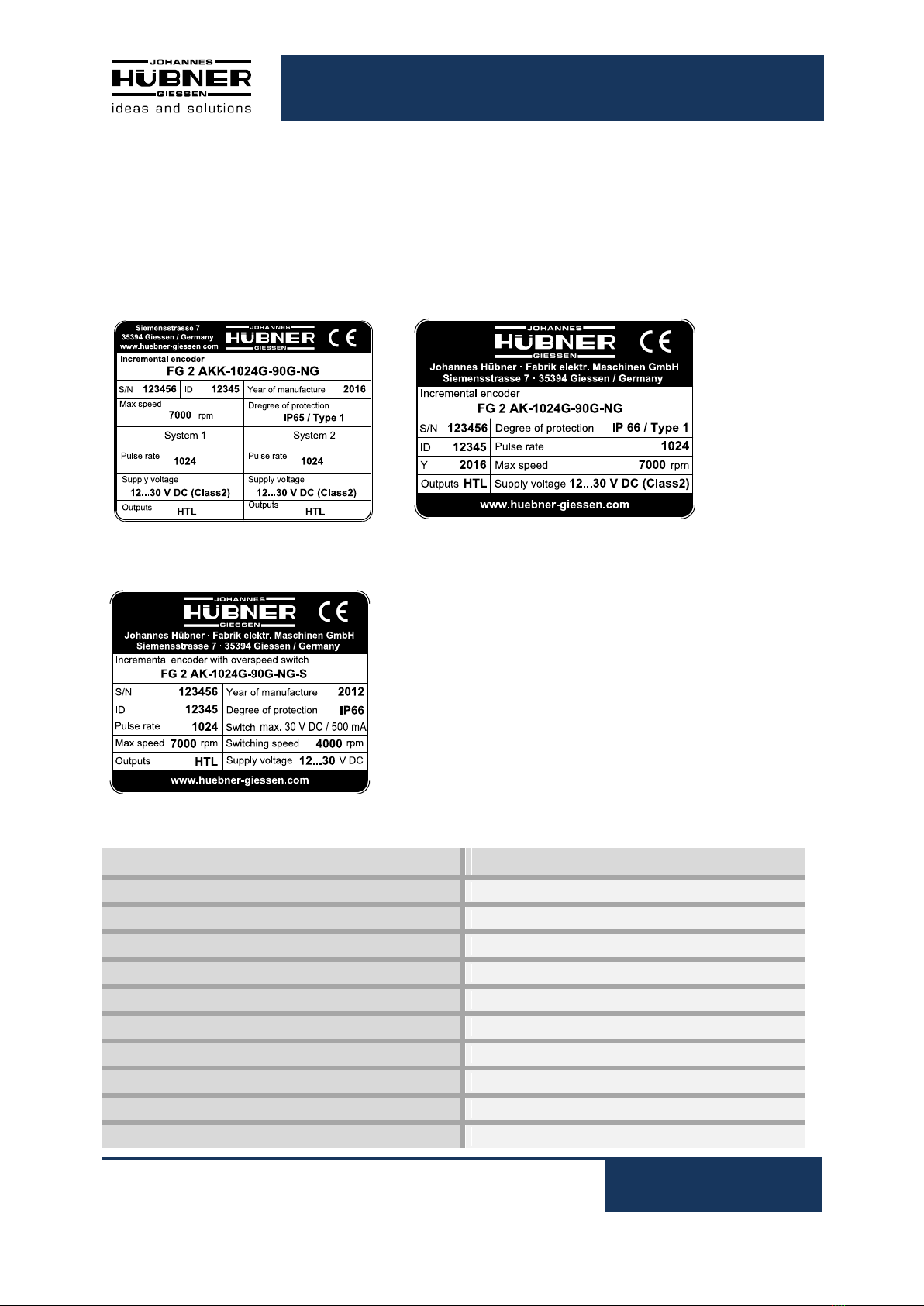
3.1 Type plate.................................................................................................................. 9
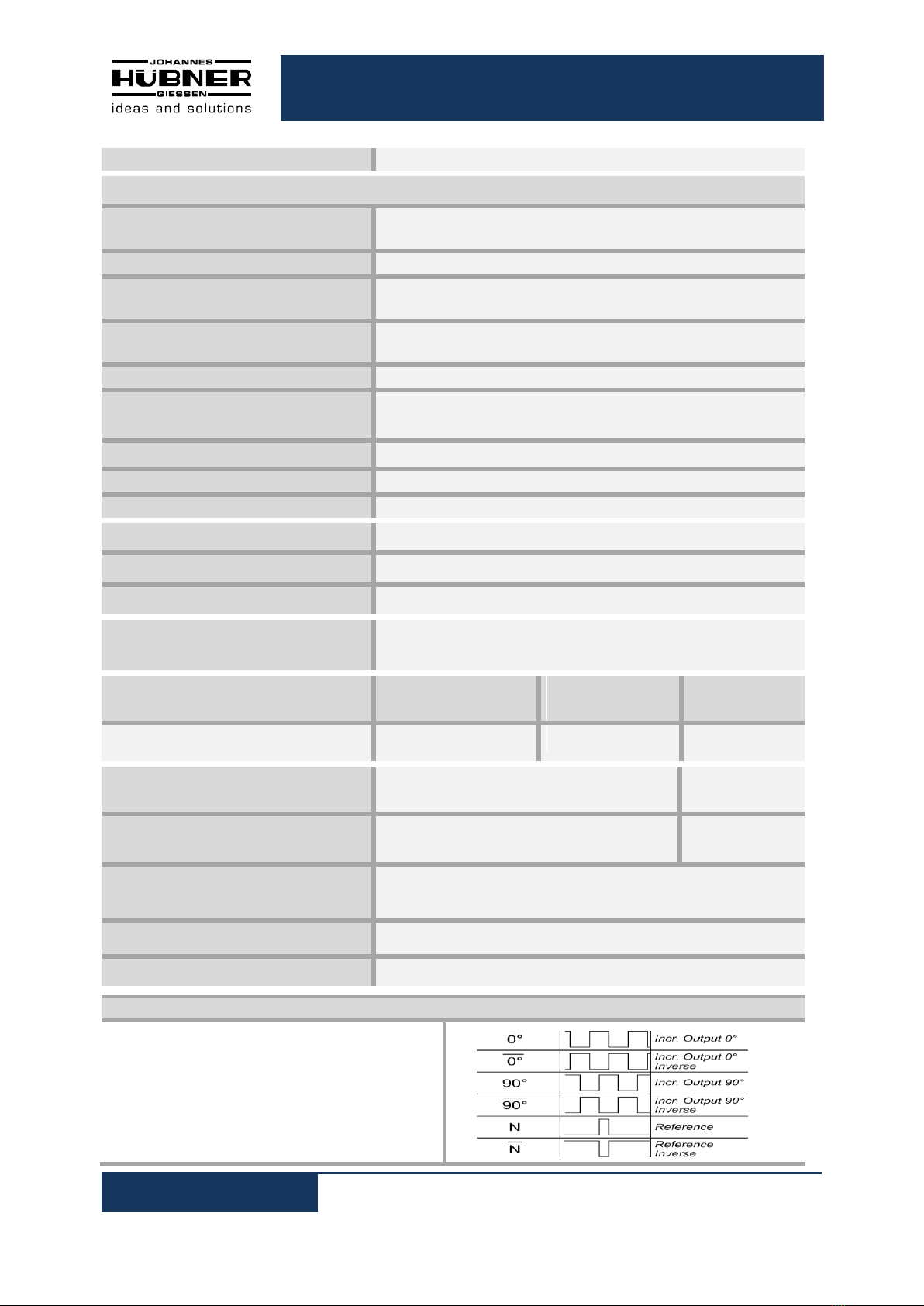
3.2 Electrical and mechanical data..................................................................................10
4Overview additional options .........................................................................................11
4.1 Option S (overspeed switch).....................................................................................11
4.2 Option LWL (signal transmission using fiber optics)..................................................11
4.3 Option AKK (double pulse output).............................................................................11
4.4 Type code.................................................................................................................12
5Transport, packaging and storage ...............................................................................13
5.1 Safety instructions for transport.................................................................................13
5.2 Goods inward inspection...........................................................................................13
5.3 Packaging / disposal.................................................................................................13
5.4 Storage of packages (devices)..................................................................................13
6Installation and commissioning....................................................................................14
6.1 Safety instructions.....................................................................................................14
6.2 Technical information................................................................................................14
6.3 Required tools...........................................................................................................14
6.4 Mounting preparations ..............................................................................................15
6.5 Mounting the encoder ...............................................................................................15
6.6 Mounting tolerances..................................................................................................17

Incremental Encoder FG 2
4
FG2_MANUAL-en_R8(2016-08-11)ID70199.doc
6.7 Electrical connection and start up..............................................................................18
6.7.1 Preparing cables ..................................................................................................18
6.7.2 Electrical connection.............................................................................................18
7Dismantling....................................................................................................................19
7.1 Safety instructions.....................................................................................................19
7.2 Dismantling the encoder ...........................................................................................19
8Faults..............................................................................................................................20
8.1 Faults table...............................................................................................................20
9Inspections.....................................................................................................................21
9.1 Safety instructions.....................................................................................................21
9.2 Maintenance information...........................................................................................21
9.3 Inspection schedule ..................................................................................................21
10Disposal..........................................................................................................................21
10.1 Disposal procedure...................................................................................................21
11Replacement parts.........................................................................................................22
12EC-Declaration of Incorporation...................................................................................23
13Dimension drawings......................................................................................................26
14Connection diagrams ....................................................................................................32
14.1 Terminal box.............................................................................................................32
14.2 Connection cable......................................................................................................33

Incremental Encoder FG 2
FG2_MANUAL-en_R8(2016-08-11)ID70199.doc
5
1General
1.1 Information about the Operating and Assembly Instructions
These Operating and Assembly Instructions provide important instructions for working with the device.
They must be carefully read prior to starting all tasks, and the instructions contained herein must be
followed.
In addition, applicable local regulations for the prevention of industrial accidents and general safety
regulations must be complied with.
1.2 Scope of delivery
Incremental Encoder FG 2, Operating and Assembly Instructions.
1.3 Explanation of symbols
Warnings are indicated by symbols in these Operating and Assembly Instructions. The warnings are
introduced by signal words that express the scope of the hazard.
The warnings must be strictly heeded; you must act prudently to prevent accidents, personal injury,
and property damage.
WARNING!
Indicates a possibly dangerous situation that can result in death or serious injury if it is
not avoided.
CAUTION!
Indicates a possibly dangerous situation that can result in minor injury if it is not
avoided.
CAUTION!
Indicates a possibly dangerous situation that can result in material damage if it is not
avoided.
NOTES!
Indicates useful tips and recommendations as well as information for efficient and
trouble-free operation.
NOTES!
Do not use a hammer or similar tool when installing the device due to the risk of damage
occurring to the bearings or coupling!
DANGER!
Life-threatening danger due to electric shock!
Indicates a life-threatening situation due to electric shock. If the safety instructions are
not complied with there is danger of serious injury or death. The work that must be
executed should only be performed by a qualified electrician.

Incremental Encoder FG 2
6
FG2_MANUAL-en_R8(2016-08-11)ID70199.doc
1.4 Disclaimer
All information and instructions in these Operating and Assembly Instructions have been provided
under due consideration of applicable guidelines, as well as our many years of experience.
The manufacturer assumes no liability for damages due to:
Failure to follow the instructions in the Operating and Assembly Instructions
Non-intended use
Deployment of untrained personnel
Opening of the device or conversions of the device
In all other aspects the obligations agreed in the delivery contract as well as the delivery conditions of
the manufacturer apply.
1.5 Copyright
NOTES!
Content information, text, drawings, graphics, and other representations are protected
by copyright and are subject to commercial property rights.
It is strictly forbidden to make copies of any kind or by any means for any purpose other
than in conjunction with using the device without the prior written agreement of the
manufacturer. Any copyright infringements will be prosecuted.
1.6 Guarantee terms
The guarantee terms are provided in the manufacturer’s terms and conditions.
1.7 Customer service
For technical information personnel is available that can be contacted by telephone, fax or email. See
manufacturer’s address on page 2.
2Safety
DANGER!
This section provides an overview of all the important safety aspects that ensure
protection of personnel, as well as safe and trouble-free device operation.
If these safety instructions are not complied with significant hazard can occur.
2.1 Responsibility of the owner
The device is used in commercial applications. Consequently the owner of the device is subject to the
legal occupational safety obligations and subject to the safety, accident prevention and environmental
protection regulations that are applicable for the device’s area of implementation.
2.2 Personnel
Installation and commissioning as well as disassembly routines must be carried out by skilled technical
staff only.

Incremental Encoder FG 2
FG2_MANUAL-en_R8(2016-08-11)ID70199.doc
7
2.3 Intended use
The device has been designed and constructed exclusively for the intended use described here.
Series FG 2 Incremental Encoders are used for measurement of rotations, for instance of electrical
and mechanical drives and shafts.
Claims of any type due to damage arising from non-intended use are excluded; the owner bears sole
responsibility for non-intended use.
For UL and CSA:
For the use in NFPA 79 applications only.
Option S
The FG 2 with option S has in addition to the incremental output a switching output.
The incremental encoder FG 2 with option S has been designed and constructed exclusively for the
intended use described here.
Series FG 2 with option S Incremental Encoders are used for speed monitoring, for instance of
electrical and mechanical drives, hoisting gear and conveying machines.
The FG 2 with option S is a device, which generates a switching signal for a superior control system.
This is realized with opening of a switch contact.
Claims of any type due to damage arising from non-intended use are excluded; the owner bears sole
responsibility for non-intended use.
2.4 Improper use
Do not use the device in potentially explosive areas.
The device must not be subjected to mechanical loads in addition to its own weight and
unavoidable vibration and shock loads that arise during normal operations.
Examples for non-permitted mechanical loads (incomplete list):
-Fastening transport or lifting tackle to the device, for example a crane hook to lift a
motor.
-Fastening packaging components to the device, for example ratchet straps, tarpaulins
etc.
-Using the device as a step, for example by people to climb onto a
motor.
2.5 Personal protective equipment
For tasks such as assembly, disassembly or commissioning the use of personal protective equipment
such as safety footwear and protective work clothing is required.
The regulations specified by the owner and that are locally specified apply.

Incremental Encoder FG 2
8
FG2_MANUAL-en_R8(2016-08-11)ID70199.doc
2.6 Special dangers
Residual risks that have been determined based on a risk assessment are cited below.
2.6.1 Electrical current
DANGER!
Life-threatening danger due to electrical shock!
There is an imminent life-threatening hazard if live parts are touched. Damage to
insulation or to specific components can pose a life-threatening hazard.
Therefore:
Immediately switch off the device and have it repaired if there is damage to the
insulation of the power supply.
De-energize the electrical equipment and ensure that all components are connected for
all tasks on the electrical equipment.
Keep moisture away from live parts. Moisture can cause short circuits.
2.6.2 Rotating shafts / hot surfaces
WARNING!
Danger of injury due to rotating shafts and hot surfaces!
Touching rotating shafts can cause serious injuries.
Therefore:
Do not reach into moving parts/shafts or handle moving parts/shafts during operation.
Close to protect from injury all access openings in flanges with the corresponding plug
screw, and provided you exposed rotating components with protective covers.
Do not open covers during operation. Prior to opening the covers ensure that all parts
have come to a standstill.
The encoder can become hot during prolonged use.
In case of contact risk of burns is existing.
2.6.3 Safeguarding against restart
DANGER!
Life-threatening danger if restarted without authorization!
When correcting faults there is danger of the power supply being switched on without
authorization.
This poses a life-threatening hazard for persons in the danger zone.
Therefore:
Prior to starting work, switch off the system and safeguard it from being switched on
again.

Incremental Encoder FG 2
FG2_MANUAL-en_R8(2016-08-11)ID70199.doc
9
3Technical Data
3.1 Type plate
Below are some nameplates for different device models shown.
Without option S or LWL
With option S
The type plate is located on the outside of the housing and contains the following information:
Englisch
Deutsch
Manufacturer, address
Hersteller, Anschrift
Type:Incremental Encoder, Year of manufacture
Typ: Inkrementaler Drehgeber, Baujahr
CE mark
CE-Kennzeichnung
Serial number (S/N)
Seriennummer (S/N)
Pulse rate
Impulszahl
Degree of protection
Schutzart
Supply voltage
Versorgungsspannung
Outputs
Ausgänge
Max. speed
Max. Drehzahl
Switching speed
Schalterdrehzahl

Incremental Encoder FG 2
10
FG2_MANUAL-en_R8(2016-08-11)ID70199.doc
3.2 Electrical and mechanical data
Pulse Rates
1024, 2048
Connection data
Supply voltage
12 V…30 VDC Ripple max. 10 %
For UL and CSA Class 2 supplied
No load-current
approx. 50 mA at 24 V
Connection
screw-type terminal Type Phoenix ZFKDS 1,5-W-5,08
(0,25 mm² - 1,5 mm²)
Connection
(Option fiber optic)
St-fiber optic plug
Outputs
Current limited, short-circuit proof push-pull line driver
Pulse height (HTL)
approx. as supply voltage
output saturation voltage < 0.4 V at IL30 mA
Output current per output
150 mA peak
Internal resistance
75 Ωat 24 V
Slew rate
200 V / µs with CL100 pF
Duty cycle
1 : 1 ± 5 %
Square wave displacement 0°, 90°
90° ± 5 %
Max. frequency
200 kHz
Encoder temperature range
-25°C … + 85°C
(UL/CSA: max. +70°C)
Degree of protection acc.DIN EN
60529
Sealing
Rotor moment of
inertia
Breakaway
torque
IP 66
(UL and CSA Type 1)
with radial shaft seal
approx. 100 gcm²
approx. 3 Ncm
Vibration resistance
DIN EN 60068-2-6 / IEC 68-2-6 (10 …
2000 Hz)
20 g (=200
m/s²)
Shock resistance
DIN EN 60068-2-27 / IEC 68-2-27 (6 ms)
200 g (=2000
m/s²)
Max. encoder shaft load
Fa, max. (axial) = 100 N
Fr, max. (radial) = 120 N
Shaft dimensions
11j6 x 30 mm
Weight
approx. 2 kg
Signal outputs
Basic channel 0° (A) and pulse channel 90° (B)
Reference pulse (N) mechanically defined; one
square-wave pulse per revolution
Each with inverted signals

Incremental Encoder FG 2
FG2_MANUAL-en_R8(2016-08-11)ID70199.doc
11
4Overview additional options
4.1 Option S (overspeed switch)
The incremental encoder FG 2 with option S has an insulated switching output. The
switching function is realized with a semiconductor, the switching speed is set in our factory
(switching hysteresis 10%).
If the set switching speed is exceeded, the switch opens.
It is recommended to save the switch circuit against an overcurrent with a fuse (0,5A).
Specification
Value
Switching speed range, factory-set
AK with solid shaft max. 6300 rpm at 1024 impulses
AK with solid shaft max. 4687 rpm at 2048 impulses
AK with hollow shaft max. 5400 rpm at 1024 impulses
AK with hollow shaft max. 4687 rpm at 2048 impulses
AL with solid shaft max. 5273 rpm at 1024 impulses
AL with solid shaft max. 2636 rpm at 2048 impulses
AL with hollow shaft max. 5273 rpm at 1024 impulses
AL with hollow shaft max. 2636 rpm at 2048 impulses
Deviation from switch:
Accuracy of measurement: 2%
Switching time TSw :<3ms
Switch data
0…30V DC/max 500mA
Max. voltage drop at closed switch: 0,7V
4.2 Option LWL (signal transmission using fiber optics)
The signals 0°, 90° and marker pulse from the incremental encoder will be encoded and
transmitted via fiber optics cable. Fiber optic cable types 50/125 µm or 62,5/125 µm are
available.
4.3 Option AKK (double pulse output)
Incremental encoder with optic scanning in redundant design. This provides the following
combinations of the output signals.
FG(HJ) 2
Output 1
(Basic unit)
Output 2
(double pulse output)
Redundant (number of pulses)
1024
1024
Redundant (number of pulses)
2048
2048
Combined (number of pulses)
1024
2048

Incremental Encoder FG 2
12
FG2_MANUAL-en_R8(2016-08-11)ID70199.doc
4.4 Type code
FG 2 AK -1024 G -90G -NG - S
Incremental encoder
Series
Connections
AK: Terminal box
AKK: Double pulse output
AL: Terminal box with
connector for ST-compatible
fiber optic plug
Pulses per rotation
1024, 2048
Basic channel 0° (A)
Pulse channel 90° (B)
each with inverted signals (not for LWL
see chapter 4.2)
NG: Option reference pulse with
inverted signal
S: Option S
JOHANNES HUEBNER FABRIK ELEKTRISCHER MASCHINEN GMBH
is listed by Underwriters Laboratories, see following Link:
http://database.ul.com/cgi-bin/XYV/template/LISEXT/1FRAME/index.html
UL File Number: E351535

Incremental Encoder FG 2
FG2_MANUAL-en_R8(2016-08-11)ID70199.doc
13
5Transport, packaging and storage
5.1 Safety instructions for transport
CAUTION!
Material damage caused by improper transport!
Observe the symbols and information on the packaging:
Do not throw - risk of breakage
Keep dry
Do not expose to heat above 40 °C or direct sunlight.
5.2 Goods inward inspection
Check the delivery immediately upon receipt for transit damage or short delivery.
Inform the carrier immediately on receipt if you determine that damage has occurred during transit
(take photos as proof).
5.3 Packaging / disposal
The packaging is not taken back and must be disposed of in accordance with the respective statutory
regulations and local guidelines.
5.4 Storage of packages (devices)
Keep dry
Keep packages dry and free from dust; protect from moisture.
Protect against heat
Protect packages from heat above 40 °C and direct sunlight.
If you intend to store the device for a longer period of time (> 6 months) we recommend you use
protective packaging (with desiccant).
NOTES!
Turn the shaft of the device every 6 month to prevent the bearing grease solidifying!

Incremental Encoder FG 2
14
FG2_MANUAL-en_R8(2016-08-11)ID70199.doc
6Installation and commissioning
6.1 Safety instructions
Personnel
Installation and commissioning must be carried out by skilled technical staff only.
WARNING!
Observe the safety instructions contained in Chapter 2 when dismantling the device!
6.2 Technical information
NOTES!
Do not use a hammer or similar tool when installing the device due to the risk of damage
occurring to the bearings or coupling!
Ambient temperature
The max. permissible ambient temperature depends on the speed and degree of protection of the
device, the signal frequency, the length of the signal cable and the place of installation (please refer to
Chapter 3.2).
Degree of protection
To fulfil degree of protection requirements the diameter of the connection cable must correspond to
that of the cable gland (please refer to Chapter 13 Dimension drawings)!
Deep groove ball bearings
FG 2 incremental encoders are fitted with maintenance-free, greased "for-life" deep groove bearings.
Bearings must be changed by the manufacturer only. Opening the encoder renders the guarantee null
and void.
Screw retention
We recommend using Loctite®243 threadlocker (medium strength) on all fastening screws to prevent
loosening.
6.3 Required tools
Spanners: 10 mm, 22 mm
Allen keys: 2 mm, 3 mm
Flat-blade screwdrivers:
Assembly grease
Loctite®243 (medium strength threadlocker)

Incremental Encoder FG 2
FG2_MANUAL-en_R8(2016-08-11)ID70199.doc
15
6.4 Mounting preparations
1. Ensure all accessories are available (please refer to Chapter 13 Dimension drawings).
NOTES!
Fastening screws and earth cable are not included in the range of supply.
2. Preparing the place of attachment: Clean the (motor) shaft, centering, bolting surfaces and
fastening threads; check for damage. Repair any damage!
6.5 Mounting the encoder
NOTES!
For a mounting example please refer to dimension drawing HM 11 M 104353 Chapter 13
Figure 1
1
9
2
10
3
12
13
4
6
8
5
14
11
15
7

Incremental Encoder FG 2
16
FG2_MANUAL-en_R8(2016-08-11)ID70199.doc
1. Lightly grease the (Motor) Schaft (1) an Centerin (9).
2. Fit coupling (2) onto (motor) shaft.
NOTES!
You must be able to mount the coupling without force. Ream out the bores of used
couplings, if necessary!
3. Secure the coupling hub on the (motor) shaft with a grub screw or cheese head screw (10)
(depending on the coupling type).
4. Fasten the intermediate flange (3) to the motor using the fastening screws (12).
NOTES!
If possible, fit the intermediate flange in a manner that ensures the screwed sealing plug
(14) points downwards!
5. Lightly grease the encoder shaft (5) and centering (4).
6. Fit the encoder (8) into both the centering (4) and coupling hub at the same time.
NOTES!
You must be able to mount the coupling without force. Ream out the bores of used
couplings, if necessary!
NOTES!
If possible, fit the device in a manner that ensures the cable gland (7) points downwards.
7. Secure the encoder with 6 screws (6).
8. Remove the sealing plug (14) from the access bore (13) to the coupling.
9. Secure the coupling hub on the encoder shaft with a grub screw or cheese head screw (11)
(depending on the coupling type).
NOTES!
To carry out this task, it may be necessary to turn the (motor) shaft to the correct
position.
10. Replace the sealing plug (14) to seal the access bore to the coupling.

Incremental Encoder FG 2
FG2_MANUAL-en_R8(2016-08-11)ID70199.doc
17
6.6 Mounting tolerances
NOTES!
Angle misalignment and parallel displacement between the (motor) shaft and the
encoder shaft are mounting errors and should be kept as small as possible.
Mounting errors
- Cause radial forces to act on the encoder shaft.
- Reduce the service life of the bearings and the coupling.
- Degrade the quality of the signals (harmonic content).
Mounting tolerances for our zero-backlash, torsion-resistant couplings HK 5 and HKD 5:
Coupling
Axial offset a
Angular error α
Parallel offset e
HK 5
± 1 mm
0.5°
-
HKD 5
± 1.5 mm
0.5°
0.5 mm

Incremental Encoder FG 2
18
FG2_MANUAL-en_R8(2016-08-11)ID70199.doc
6.7 Electrical connection and start up
NOTES!
You must observe applicable EMC guidelines when routing cables!
NOTES for UL and CSA!
Do only use copper cables!
6.7.1 Preparing cables
1. Strip cable insulation. The cable for the signal and supply line is shielded, the cable for the
option S and the cable for LWL will not be shielded.
2. Crimp wire-end ferrules.
6.7.2 Electrical connection
1. Open the terminal box cover (15, Fig.1).
CAUTION!
Do not allow moisture to enter the terminal box when the cover is open!
2. Remove the cap of the cable glands (17, Fig.1).
3. Feed the cable into the terminal box trough the cable glands.
NOTES!
The signal cable shielding has to be connected directly to the housing via the EMC
cable gland.
To achieve an effective shielding the cable shield must also be connected in the
electrical cabinet.
4. Tighten the cable gland using a spanner.
NOTES!
Prior to delivery cable glands and blanking plugs are tightened finger tight only. To
ensure that the terminal box is reliably sealed tighten all cable glands and blanking plugs
before starting up for the first time.
5. Use a spanner to tighten the cable gland until the cables are securely clamped and properly
sealed.
NOTES!
Prevent lateral pulling forces acting on the cable so as not to impair the degree of
protection of the cable gland.

Incremental Encoder FG 2
FG2_MANUAL-en_R8(2016-08-11)ID70199.doc
19
6. Connect the supply voltage, the signal cable and possibly option S (please refer to the
connection diagrams, Chapter 14).
CAUTION!
Do not apply supply voltage to the signal outputs, as this will destroy the device!
7. Close the terminal box cover.
NOTES!
Before closing the terminal box cover check and if necessary clean both seal surfaces
and the gasket.
CAUTION!
Ensure when closing the terminal box cover that no cable becomes jammed.
For encoders with option S only:
1. Remove the blind plug from inside of the housing
2. Remove the cable gland
3. Close the opening with the blind plug
7Dismantling
7.1 Safety instructions
Personnel
Dismantling must be carried out by skilled technical staff only.
WARNING!
Observe the safety instructions contained in Chapter 2 when dismantling the device!
NOTES!
Do not use a hammer or similar tool when dismantling the device due to the risk of
damage occurring to the bearings or coupling!
7.2 Dismantling the encoder
Disconnect all electrical cable prior to beginning any work.
To dismantling the encoder follow the instructions given in Chapter 6.5 in the reverse order.

Incremental Encoder FG 2
20
FG2_MANUAL-en_R8(2016-08-11)ID70199.doc
8Faults
8.1 Faults table
Faults
Possible cause
Remedy
Switch does not close
(only by option S)
No supply voltage
Control: LED in the terminal box
does not shine
Check connection cable and
supply voltage
Error LED does not shine:
Rotation speed above the
switching speed
Adjust the suitable rotation speed
Error LED is shining:
Evaluation of rotation speed is
faulty.
Disconnect power supply and
switch on again
Moisture in the terminal box
Soiled terminal box gasket or
seal surfaces
Clean terminal box gasket and
seal surfaces
Damaged terminal box gasket
Replace terminal box gasket
Cable gland/blanking plug not
tightened
Tighten cable gland/blanking
plug
Unsuitable cable for cable gland
Use suitable cable and cable
glands
No output signals
Supply voltage not connected
Connect supply voltage
Connection cable reversed
Wire correctly
Output signals subject to
interference
Unsuitable cable
Use data cable with conductors
arranged as twisted pairs and
common shield
Cable shield not connected
Connect cable shield at both
ends
Cable routing not EMC compliant
Observe applicable EMC
guidelines when routing cables
Signal interruptions
Signal end stage overloaded
Check pin assignment; observe
connection diagram
Do not assign unused outputs
Outputs short-circuited
Do not connect outputs with
supply voltage or GND
Contact Hubner-Service (page 2) if none of the remedies listed above provides a solution!
Other Hubner Measuring Instrument manuals

Hubner
Hubner Cobolt 06-MLD 940 nm User manual

Hubner
Hubner C-FLEX User manual

Hubner
Hubner Cobolt Tor Series User manual

Hubner
Hubner Cobolt 06-01 Series User manual

Hubner
Hubner Cobolt Odin Series User manual

Hubner
Hubner Cobolt 04-01 Series User manual

Hubner
Hubner HM35 User manual

Hubner
Hubner Cobolt 05-01 Series User manual

Hubner
Hubner Cobolt DPSS User manual