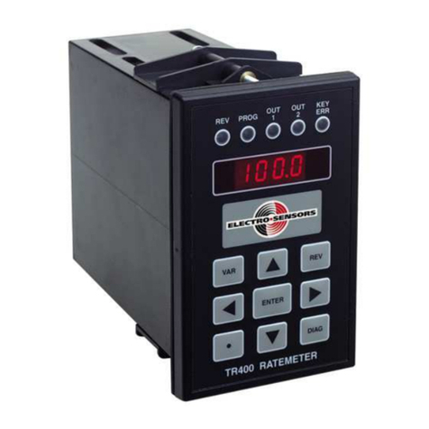
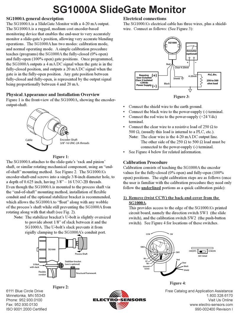
Electro-Sensors SA420 User manual

ENT
SA420
OUT%
VAR RATE
Description:
Electro-Sensor’s SA420 Signal Conditioner provides an analog signal
directly proportional to the speed of a monitored shaft. The 0-10 VDC
and 4-20 mA outputs can be sent to a chart recorder, digital display, PLC,
loop controller, drive speed controller, or other control or monitoring
devices. The wide voltage range and wave shape exibility of the
SA420’s sensor input circuitry allow it to translate signals from Hall-
Effect Sensors, proximity switches, magnetic sensors, and a wide variety
of other pulse generator devices into analog outputs.
Sensor Installation:
The standard sensor is supplied with a mounting bracket and two jam
nuts. The explosion-proof sensor is supplied with a slotted mounting
bracket. Sensors should be installed so the centerline of the magnets
pass in front of the center of the sensor as the disc or wrap rotates. When
using the pulser disc, the center of the magnetized area of the disc,
shown as Dimension B in gures 1 and 3, is 1-3/4 inches from the center
hole of the disc. The gap distance between the sensor and the disc or
wrap, Dimension A In the diagrams, is 1/4-inch ±1/8 inch. To achieve
the proper gap distance, adjust the jam nuts holding the standard sensor
in the mounting bracket, or adjust the position of the explosion-proof
sensor using the slots on its mounting bracket.
Pulser Disc:
The end of the shaft to be monitored must be center drilled to a depth of
1/2-inch with a No. 21 drill and tapped for 10-32UNF. After applying
Loctite™ or a similar adhesive on the threads to keep the pulser disc
tight, the pulser disc should be attached, decal side out, with the supplied
10-32UNF machine screw and lock washer.
Pulser Wrap (optional):
Pulser Wraps are custom manufactured to t the shaft they will be
mounted on. When the wrap is shipped, four Allen-head cap screws hold
the two halves of the wrap together. These screws must be removed so
that the wrap is in two halves. Place the halves around the shaft, reinsert
the screws and torque them to 5 foot-pounds max.
A
B
Figure 1: Standard Sensor with 255 Pulser Disc
A
A
Figure 2: Standard Sensor with optional Pulser Wrap
B
A
Figure 3: Explosionproof Sensor with 255 Pulser Disc
A
A
Figure 4: Explosionproof Sensor with Pulser Wrap
SA420 Signal Conditioner
6111 Blue Circle Drive
Minnetonka, MN 55343
Phone: 952.930.0100
Fax: 952.930.0130
ISO 9001:2000 Certied
Free Catalog and Application Assistance
1.800.328.6170
Visit Us Online
www.electro-sensors.com
990-001700 Revision G

Wiring Connections:
Sensor Wire connections:
Terminal Model
906/907
All other
ESI
Sensors
Mag
Pickup
Logic
Level
ESI
Prox
5 Supply Red Red N/C Brown
6 Signal Black Clear + Signal Black
7 Ground Clr/Shd Blk/Shd - Common Blue
Power Connections:
Terminal 115 VAC
Standard
230 VAC
Optional
12 VDC
Optional
24 VDC
Optional
2 Hot L1 Hot (+)Positive (+)Positive
10 Neutral L2 Hot (-)Negative (-)Negative
Analog Output Connections:
Terminal 4-20 mA Terminal 0-10 VDC
3(+) High 9 (+) Positive
4 (-) Low 8 (-) Negative
Terminal Connection
8
765
4
9
1110 12
3
1 No Connect
2 Hot +
3 4-20mA +
4 4-20mA -
5 Sensor Supply
6Sensor Signal A
7 Sensor Ground
80-10 VDC -
90-10 VDC +
10 Neutral -
11 Sensor Signal B*
*Advanced mode allows for bidirectional sensing. See website for
addendum on using the SA420 in advanced mode.
Figure 5: Terminal Block wiring
Calibration:
There are four buttons on the front panel used for calibration:
▲ Up Arrow Button is used to change the value of the position in focus
(ashing), while in the calibration mode. While in standard mode, this
button will toggle the display between frequency input (hertz) and output
percentage.
◄ Left arrow button is used to move the focus to the next position when
in the calibration mode of 4-20 mA or 0-10 VDC.
•Decimal Point Button is used to change the position of the decimal
point while in the calibration mode.
ENT Enter Button is used to enter or exit the calibration mode.
Variable 1 is used to set the maximum frequency, which will equal
100% output (10 VDC or 20 mA); 4 mA or 0 VDC is always equal to
.01 Hz. The default value for variable 1 is 240.0 Hz. With the standard
sensor and disc, this is equal to 1800 rpm at 8 pulses per revolution.
Maximum Frequency = (RPM X PPR) / 60
Variable 2 is used to select your sensor output type. The default is set to
0. *(All Standard ESI sensors are NPN open collector output.)
Variable 2 value Type of Sensors
0NPN*
1PNP
2 Magnetic Pickup
3Logic Level
Variable 3 is used for analog ltering. The number entered here
represents the number of pulses that are to be averaged. The greater the
number the smoother the output. The down side to a large number is
response will suffer at lower speeds. Valid numbers are 1 to 250. The
factory default is 8.
ENT
SA420
OUT%
VAR RATE
Calibrating The Unit:
To enter the calibration mode, push the ENT button once. PR1 will be
displayed for one second, and then the value of variable 1 is displayed.
The right most digit of variable 1 will be ashing, which indicates that
this digit has the focus and can be changed. Pressing the ▲button will
increment the ashing digit. The ◄ button will advance the focus to
the next digit to be changed. The •(DP) button will scroll the decimal
point across the display from right to left. When the correct value is
programmed into the vari able, press the ENT button to store the variable
in memory and access variable 2. You can now change the sensor output
type if necessary or press the ENT button to return to standard mode.
2-4
Free Catalog and Application Assistance
1.800.328.6170
Website: www.electro-sensors.com
990-001700 Revision G

SA-420 Dimensional Drawings:
Dimensions in Inches
3.00
5.63
2.28
1.75
1.66
Figure 6: SA-420
2.28
1.18
1.34
0.85
1.44
6-32
1.66
Figure 7: Terminal Block
4.00
0.196
0.250
Figure 8: 255 Pulser Disc
2.00"
2.51"
2.00"
2.00"
1.25"
1.00"
1.00"
1.120"
Figure 9: Standard Sensor
2.38
5.53
1.16
3.38
1.00
1" NPT
1.63
3.75
1.88
Nut &
Lockwasher
0.56
1.25
4.63
Figure 10: Explosionproof Sensor
1.00
.43
0.13
2
.75 1.63
.32
.56
2.88
1.25
2.03.39
0.33
Figure 11: Explosionproof Sensor Bracket
3-4
Free Catalog and Application Assistance
1.800.328.6170
Website: www.electro-sensors.com
990-001700 Revision G

Troubleshooting Guide
Problem Possible Solution
Unit Dead Check for proper supply at
terminals 2 and 10. See gure 5 on
page 2
No Analog out with zero
hertz displayed
Check for Sensor supply. It should
be Approximately 13.6 VDC
Check sensor Gap distance
Check Sensor Type (Variable 2)
Unit displays a
frequency but the analog
is incorrect
Check variable 1 for correct
frequency
Check your on the correct
analog output, voltage(VDC) or
current(mA)
Analog is unstable Check gap distance
SA420 General Specications:
Input Power Input Current Fuse Type (F2)
115 Vac, 60Hz (std) 2.5 VA Sloblo .032A 5X20
230 Vac, 60Hz (opt) 2.5 VA Sloblo .032A 5X20
12 Vdc (opt) 165 mA Sloblo .250A 5X20
24 Vdc (opt) 135 mA Sloblo .200A 5X20
Input Signal Parameters
Sensor Supply 12 VDC (unregulated) @50 mA max.
Programmable Types
Open collector NPN / PNP
Logic Level 5 V Nom. 3 V Min.
Magnetic Sensor +/- 75 MV Min.
Max. Amplitude 25 Vpk-pk Maximum
Frequency Range 0.01 Hz to 10 kHz
Minimum Input for
Full Scale Output
0.5 Hz = 3.8 RPM @ 8 PPR
(Lower full scale range is available,
consult Factory)
Analog Output Signal Parameters
Types 0 - 10 VDC, 4 - 20 mA with 500Ω
load max.
Accuracy (typical) 0.1% Linearity for both outputs
Step Response Time Parameters
50 Hz Input and above 10 to 90% = 50 ms.
Below 50 Hz Input 10 to 90% = 30 ms + 1/Hz Input
frequency
Physical/Envlronment Parameters
Mounting DIN rail mount or Stand alone
Operating temperature 0°C to +60°Cz
Storage temperature -65°C to +125°C
Electrical Connections 11 Position DIN rail terminal
block
DIN rail enclosure rating NEMA 1
255 Pulser Disc (std.) Parameters **
Material Nylon 12 Std,
(opt; PVC, Alum, Stainless-Steel)
Dimensions 4-inch diameter x 1/4-inch thick
Operating Temperature -40ºC to +60ºC* (Nylon, PVC)
Operating Temperature -40ºC to +150ºC* (Alum, SS)
Pulser Wrap (optional) Parameters **
Material PVC Std.
(opt; Aluminum or Stainless-Steel)
Operating Temperature -40ºC to +60ºC* (PVC)
Operating Temperature -40ºC to +150ºC* (Aluminum, SS)
906 Sensor (Standard) Parameters **
Material Sensor Body Aluminum 3/4 - 16UNF thread
Material Mount Bracket Plate steel
Output Types NPN open collector current sinking
20 mA max
Signal Cable 3-conductor shielded, 10 feet length
std. (50 ft. or 100 ft. optional)
Operating Temperature -40ºC to + 60ºC*
Air Gap 1/4 inch +/- 1/8 inch with standard
255 Pulser disc (1/2” magnets)
907 Explosionproof
Sensor (optional)
Parameters **
Class I, Div 1, Group D
Class II, Div 1, Groups E, F, G
UL File: E249019
Mounting Bracket
Material
Plate Steel U-Bolt Assembly
Other Specications Similar to 906 standard sensor
Specications are subject to change without notice.
*For higher or lower temperature ranges, consult factory.
** For details on Discs, Wraps and Sensors, consult factory
or visit our website.
4-4
Free Catalog and Application Assistance
1.800.328.6170
Website: www.electro-sensors.com
990-001700 Revision G
Other Electro-Sensors Measuring Instrument manuals
Popular Measuring Instrument manuals by other brands

Ampetronic
Ampetronic Loopworks Measure R1 Quick-Start Guide & Handbook

Magnetrol
Magnetrol Pulsar R96 Functional safety manual

Owon
Owon PC321 quick start guide

Aichi
Aichi SD Series instruction manual

Berger & Schroter
Berger & Schroter 30894 operating instructions

ATI Technologies
ATI Technologies 2i Operation and maintenance manual

Morrison Bros. co.
Morrison Bros. co. 1218C Installation, operation and maintenance instructions

Teracom
Teracom TCW112-CM user manual

doble
doble SFRA user guide

Quantum Composers
Quantum Composers miniSystem Series operating manual

Badger Meter
Badger Meter Primo Advanced BMAG-350-icpf Instruction and operation manual

AccuEnergy
AccuEnergy AcuRev 1310 Series user manual