HULTDINS SuperSaw 651S User manual

Installation manual
SuperSaw 651S

2013– HULTDIN SYSTEM AB.
This publication applies to the following models:
SuperSaw 651S S/N 053-0024 and up
This publication contains instructions for the installation and maintenance of the SuperSaw 651S grapple saw units. The
instructions cover general information, procedures and specifications applicable to this grapple saw. If doubt should arise
concerning the validity of the instructions please consult the nearest dealer for more detailed information.
Illustrations, technical information and specifications were, as far as we have been able to judge, correct at the time of print.
However, we reserve the right to, without prior notice, revise specifications, instructions, equipment, etc. as a result of
ongoing product improvement activities.
No part of this publication may without approval of HULTDIN SYSTEM AB be translated, reproduced, stored or
transmitted electronically, mechanically, photographically or in another way not specified here.
Even if all conceivable measures have been taken to make the contents as complete as possible, HULTDIN SYSTEM AB
takes no responsibility for possible damages that may arise as a result of the instructions not being followed or improper use
of the product
Important!
The parts and components used in HULTDIN SYSTEM AB’s products are specifically chosen. Therefore original
spare parts are always the best alternative in a possible need of repairs or upgrading.
All service and repairs should be carried out by qualified service personnel or an authorized repair shop with suitable tools
and lifting devices.
This publication is published by: HULTDIN SYSTEM AB
Skolgatan 12
SE-930 70 MALÅ
Sweden

en_ss651TOC.fm SuperSaw 651S
CONTENTS
Contents Page Contents Page
Safety instructions.................................................... 4
Welding ................................................................ 5
Modifying the equipment..................................... 5
Chain shot hazard................................................. 5
Operator and bystander safety........................ 5
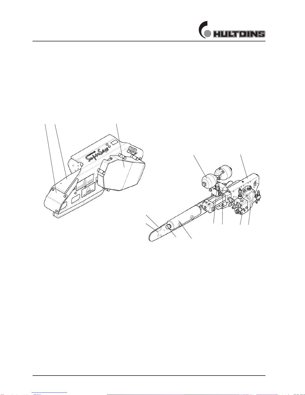
Product description.................................................. 6
Main parts, Grapple saw ...................................... 6
Lubrication oil tank.............................................. 7
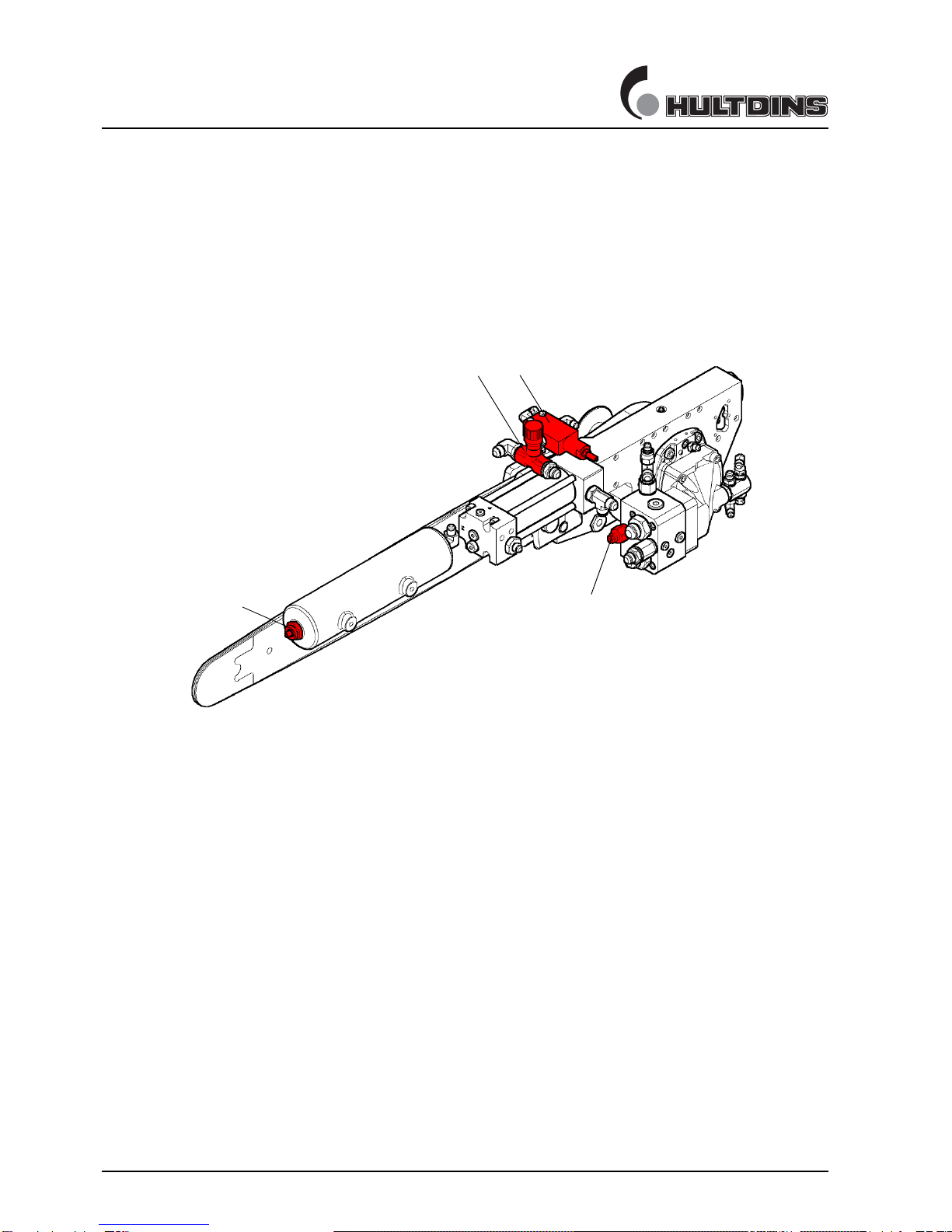
Adjustment valves, Grapple saw.......................... 8
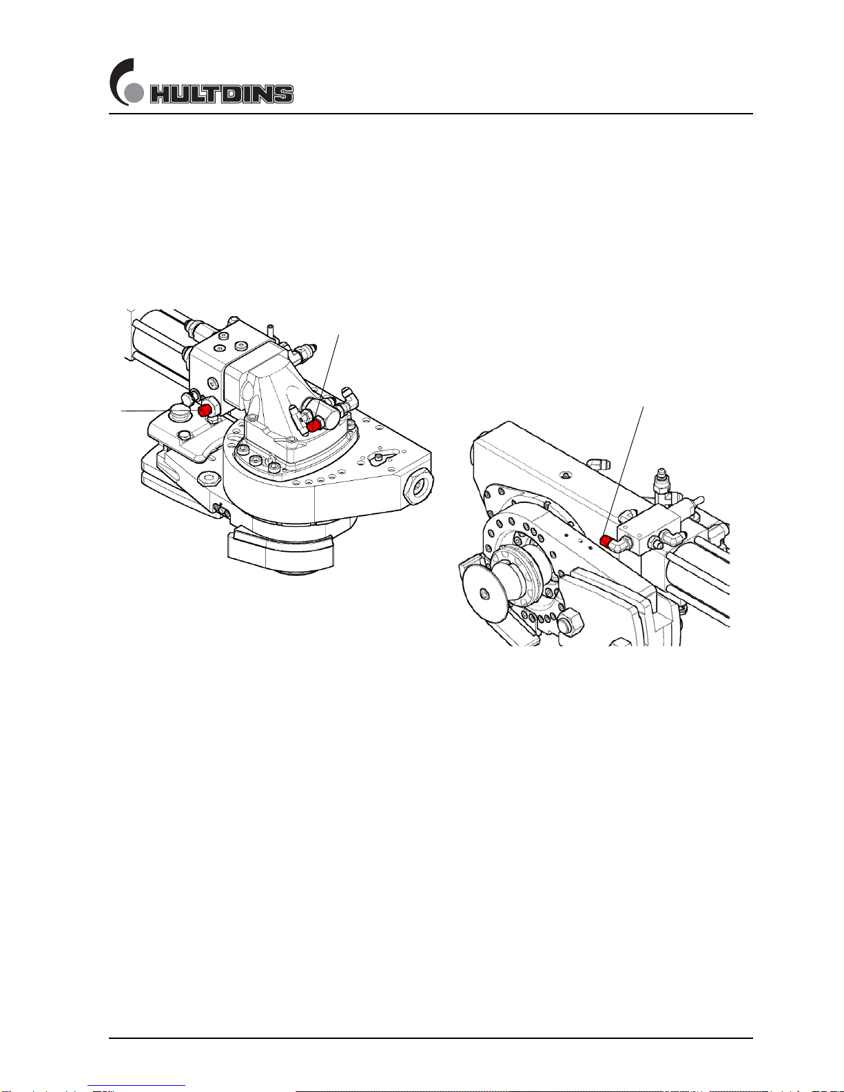
Hydraulic pressure test points.............................. 9
SuperCut 300...................................................... 10
Labeling.............................................................. 11
Technical Data........................................................ 12
SuperSaw 651S - 40cc ....................................... 12
SuperSaw 651S - 60cc ....................................... 13
Rotator bracket HD............................................ 14
Special tools....................................................... 15
Hydraulic diagram SuperSaw 651S................... 17
Functional description........................................... 18
Chain lubrication system.................................... 18
Installation.............................................................. 19
Where to install the grapple saw? ...................... 19
Installing HD rotator bracket ............................. 20
Hydraulic installation......................................... 21
Initial upstart.......................................................... 22
Saw motor upstart .............................................. 22
Adjusting saw bar feed out pressure .................. 23
Adjusting saw bar feed out................................. 24
Adjusting saw bar retraction .............................. 24
Adjusting chain tension pressure ....................... 25
Bleeding the chain tension system..................... 26
Procedures .............................................................. 27
Replacing saw chain........................................... 27
Replacing saw bar.............................................. 28
Replacing bar holder .......................................... 29
Replacing drive sprocket.................................... 30
Refilling chain lubrication oil ............................ 31
Maintenance instructions...................................... 32
Regular maintenance.......................................... 32
Daily maintenance........................................ 32
Lubrication ................................................... 33
Fastener joints and hydraulic hoses.............. 33
The first month of operation .............................. 33
Fasteners....................................................... 33

SAFETY INSTRUCTIONS
4Safety instructions en010501_sc.FM
Safety instructions
This page describes important safety instructions, which
the operator’s of Hultdins SuperFell, SuperSaw and
SuperCut attachments should have a good knowledge of
before the equipment is used.
This manual should be available at all times so that the
operator is able to follow safety regulations and the
procedures of maintenance activities..
Note! Read carefully and understand the following
information with concerns to safe operation practices
before operating this equipment.
Important!
The owner and the operator are responsible for
following all safety regulations and that the machine
is safely equipped.
Important!
Check the machine for damages at the beginning of
each shift.
Important!
Inspect and lubricate the unit at the beginning of each
shift. Tighten all fasteners regularly.
Important!
All service and repairs should be carried out by
qualified personnel or an authorized repair shop with
suitable tools and lifting devices.
Important!
When working on the saw chain always ensure the
engine is shut off and wear safety gloves to prevent
injuries. Remove the saw chain when making any
adjustments or servicing the saw unit.
Important!
Never adjust any hydraulic pressures without using a
pressure gauge.
Important!
Consider the environment. Plug all connections to
avoid unnecessary spill of oil.
Warning!
The hydraulic input of the equipment must not
exceed the recommended maximum rating as
structural failure could occur, resulting in injury and
damaged equipment.
Warning!
Before performing any maintenance or service work,
lower the attachment to the ground and shut off the
engine. Turn off any master shut-offs and do not
allow personnel in the cab.
Warning!
Keep all windows and doors securly closed when
operating.
Warning!
Never touch or stand close to the pressurized
cylinders and hydraulic hoses.
Warning!
The attachment has sharp edges. Use proper
wrenches and protective gloves when working on the
attachment.
Fig. 1 The operating area of the saw attachment and the
recommended safety distance
90 meters/300 feet
Warning!
When operating this equipment ensure all other
personnel remain at least 90 meters (300 feet) clear
of the machine. Turn the machine off immediately if
anyone enters this safety zone.
Warning!
Training or demonstration of this equipment should
be performed from an operator´s cab approved by
national regulations. Observers should always
remain at least 90 meters (300 feet away).
Warning!
Always use High Speed saw chains with 3/4” pitch
saw units.

SAFETY INSTRUCTIONS
en010501_sc.FM Safety instructions 5
Welding
In case of a structural repair of the equipment, when
welding may be needed, consult the dealer for
recommended instructions.
When welding on the attachment the following steps
must be taken:
• Make sure that fire-extinguishing equipment is
available.
• Clean the area around the welding area to
eliminate any fire hazard.
• Connect the ground wire so the welding current
does not pass over any bushings.
• Place the ground wire as close to the welding area
as possible.
Modifying the equipment
It is not approved to:
• Modify the equipment without the consent of
HULTDIN SYSTEM AB.
• Alter the function of the equipment without the
consent of HULTDIN SYSTEM AB.
• Use spare parts other than original HULTDINS
parts.
Chain shot hazard
Operator and bystander safety
Because of the high speeds, high stress, heavy loads, wear
factors and varying levels of repair and maintenance given
to saw-chain based machines, there is a possibility that
chain or chain pieces can be thrown from the machine at
high speed and enormous energy. Operators and bystanders
are exposed to a risk of serious injury.
Machines should be designed with appropriate guards and
shields, and care should be taken to minimize the exposure
of users and bystanders to the cutting plane of the saw.
Warning!
There is risk of serious injury or death to machine
operators and bystanders from “Chain Shot”, which is
the high-speed ejection of chain parts that can occur
in the event of a derailed or a broken chain. For
maximum protection, machines should be equipped
with an energy-absorbing chain shot guard.

PRODUCT DESCRIPTION
6 SuperSaw 651S en011102a_ss651.fm
Product description
Main parts, Grapple saw
The SuperSaw 651S grapple saw consists basically of a frame, a saw unit and a
hydraulic system. The illustration shows the location of the main parts.
ill. 2 Main parts SuperSaw 651S
1Frame
2 Saw motor cover
3 Cover plate
4 Adjusting valve for saw bar feed out speed
5 Saw motor manifold with adjusting valve for saw bar feed out pressure
6 Saw unit
7 Saw motor
8 Accumulator for saw motor case drain
9 Air tank for saw bar retraction
10 Air nippel for air-pressure adjustment
11 Saw bar
12 Saw chain
13 Adjusting valve for chain tension pressure
12
3
5
6
7
8
910
11
12
413

PRODUCT DESCRIPTION
en011102d_ss651.fm SuperSaw 651S 7
Product description
Lubrication oil tank
The SuperSaw 651S grapple saw can be equipped with two different lubrication oil
tanks. One integrated 6,1 litre tank, or an external 26,5 litre tank. The design and
placement of the two different tank is shown below.
ill. 3 Lubrication oil tanks, SuperSaw 651S
1 6,1 litre oil tank
2 26,5 litre oil tank
1
2

PRODUCT DESCRIPTION
8 SuperSaw 651S en011102b_ss651.fm
product description
Adjustment valves, Grapple saw
The SuperSaw 651S grapple saw has the following adjustment valves. The location
of the valves shows on the illustration.
ill. 4 Adjustment valves
1 Pressure regulating valve for saw chain tension pressure
2 Pressure regulating valve for saw bar feed out pressure
3 Air nipple for saw bar retraction adjustment
4 Restrictor valve for saw bar feed out speed adjustment
1
32
4

PRODUCT DESCRIPTION
en011102c_ss651.fm SuperSaw 651S 9
product description
Hydraulic pressure test points
The SuperSaw 651S grapple saw has the following hydraulic pressure test points.
The location of the test points shows on the following illustration.
ill. 5 Hydraulic pressure test points
1 Test point for saw bar feed out pressure
2 Test point for chain tension pressure
3 Test point for saw motor case drain pressure
12
3

PRODUCT DESCRIPTION
10 SuperCut 300 en011102_sc300.fm
Product description
SuperCut 300
The SuperCut 300 saw unit is made up of the following main parts.
1. Housing with integrated 4-point bearing/gear drive
2. Tension device
3. Bar holder
4. Saw motor
5. Feed out cylinder
6. Lubrication oil pump
7. Cut control (option)
ill. 6 Main parts SuperCut 300
1
2
3
47
56

PRODUCT DESCRIPTION
en011303_ss651.fm SuperSaw 651S 11
Märkning SuperGrip SG II
CE-marking
Warning label
Product marking
Warning label
Product description
The SuperSaw 651S grapple saw, which together with
SuperGrip, SuperGrip II or SuperGrip TL grapples is
generally mounted on cranes intended for on road- and off
road vehicles. SuperSaw 651S is only intended to be used
for timber, pulp- and waste wood systems.
SuperSaw 651S must not be used for felling
applications,as there is a risk that the grapple arms or other
parts of the grapple or grapple saw may fail, which could
result in injury or damaged equipment.
Labeling
SuperSaw 651S is labeled with serial number, model num-
ber, mfg. year, weight and a CE-label according to the fol-
lowing illustration.

TECHNICAL DATA
12 SuperSaw 651S en011104a_ss651.fm
Technical Data
SuperSaw 651S - 40cc
Dimensions
Total weight w/o lubrication oil tank 257 kg
Length ‘A’ 1397 mm
Width ‘B’ 234,5 mm
Height ‘C’ 511 mm
Width ‘D’ 148 mm
Saw bar 3/4” 100 cm
Hydraulic system
Saw motor displacement 40 cm3
Min. hydraulic pressure, saw motor 18,0 MPa*
Min. hydraulic flow, saw motor 172 lpm *
Hyd. pressure, saw bar feed out‘P1’ 6,5 - 8,0 MPa
Hyd. pressure, chain tensioning‘P2’ 5,0 - 5,5 MPa
Gas pressure, accumulator ‘P3’ 0,1 MPa
Air pressure, saw bar retraction‘P4’ 1,2 - 1,4 MPa
Chain lubrication
Type of lubrication Proportional
lubrication volume @90° feed out 25 ml
Lub. oil tank capacity 6,1 lit. / 26,5 lit.
Weight, 6,1 litre oil tank 8,5 kg
Weight, 26,5 litre oil tank 29 kg
* Max. saw chain speed and Max. power input to the saw
chain may NEVER exceed recommendations from each
saw chain manufacturer.

TECHNICAL DATA
en011104b_ss651.fm SuperSaw 651S 13
Technical Data
SuperSaw 651S - 60cc
Dimensions
Total weight w/o lubrication oil tank 260 kg
Length ‘A’ 1397 mm
Width ‘B’ 234,5 mm
Height ‘C’ 511 mm
Width ‘D’ 148 mm
Saw bar 3/4” 100 cm
Hydraulic system
Saw motor displacement 60 cm3
Min. hydraulic pressure, saw motor 18,0 MPa*
Min. hydraulic flow, saw motor 172 lpm *
Hyd. pressure, saw bar feed out‘P1’ 6,5 - 8,0 MPa
Hyd. pressure, chain tensioning‘P2’ 5,0 - 5,5 MPa
Gas pressure, accumulator ‘P3’ 0,1 MPa
Air pressure, saw bar retraction‘P4’ 1,2 - 1,4 MPa
Chain lubrication
Type of lubrication Proportional
lubrication volume @90° feed out 25 ml
Lub. oil tank capacity 6,1 lit. / 26,5 lit.
Weight, 6,1 litre oil tank 8,5 kg
Weight, 26,5 litre oil tank 29 kg
* Max. saw chain speed and Max. power input to the saw
chain may NEVER exceed recommendations from each
saw chain manufacturer.

TECHNICAL DATA
en011104a_0726113.fm SuperSaw 13
Technical Data
Rotator bracket HD
Dimensions
Total weight incl. hoses 101 kg
Length ‘A’ 75 mm
Length ‘B’ 245,5 mm
Height ‘C’ 154 mm
Rotator hole pattern M16 / 173 mm
M20 / 203 mm

TECHNICAL DATA
En011104c_ss651.fm SuperSaw 651S 15
Technical data
Special tools
The following special tools are supplied with the unit and
required when servicing the grapple saw.
Air pump
The air-pump is used when adjusting the saw bar
retraction speed.
Installation tool
The installation tool, P/N 0690149, is required when
replacing the check valve for the chain tensioning.
Check valve key
The key, P/N 0696011, is used when
replacing the check valve for the chain lubrication. It is
also used when bleeding the chain tensioning circuit.
Pressure gauge hose
The pressure gauge hose, P/N 0724042, is used to connect
a pressure gauge to the pressure test points.
ill. 7 Air-pump, P/N 0138042
ill. 8 Installation tool, P/N 0690149
ill. 9 Key, P/N 0696011
ill. 10 Pressure gauge hose, P/N 0724042

TECHNICAL DATA
16 SuperSaw 651S En011104c_ss651.fm
Eye bolt
The eye bolt, P/N 0108118, makes it easier to in a secure
way lift and handle the grapple saw during installation or
service.
Retraction tool
The retraction tool, P/N 0696116, is used to retact the bar
holder when replacing the saw chain or bleeding the
tension circuit.
ill. 11 Eye bolt, P/N 0108118
ill. 12 Retraction tool, P/N 0696116

TECHNICAL DATA
En011104d_ss651.fm SuperSaw 651S 17
Technical data
Hydraulic diagram SuperSaw 651S
1. Tension device
2. Saw motor manifold
3. Air tank for saw bar retraction
4. Pressure regulating valve for chain tensioning
5. Pressure regulating valve for saw bar feed out pressure
6. Saw motor
7. Main valve on carrier*
8. Saw bar feed out cylinder
9. Grapple cylinder
10. Restrictor check valve for saw bar feed out speed
11. Rotator
12. Accumulator for saw motor case drain
13. Check valve
14. Pilot valve for chain tensioning
15. Bleed valve for chain tensioning
16. Pressure test point
* Required on carrier, but not supplied with the grapple
saw.
P1 - P4, see Technical data
ill. 13 Hydraulic diagram
1
15
14
16(P2)
4
2
8
11 93(P4)
16(P1)
5
13
16
10
12(P3) 6
7
13
13

FUNCTIONAL DESCRIPTION
18 SuperCut 300 en011105b_sc300.FM
Functional description
Chain lubrication system
The SuperCut 300 is equipped with a lubrication oil pump
integrated with the feed out cylinder. The lubrication oil
pump supplies oil via a piston operation to the saw chain
during the entire feed out process.
The lubrication oil pump is fed with oil from the oil tank
(1), trough the inlet check valve (2) and to a reservoar in
the piston rod (3).
When the saw bar (8) is fed out, the oil goes through the
outlet check valve (4), via a hydraulic hose (5) to the
swivel in the saw motor (6) and finally through the bar
holder (7) to the saw bar (8).
The purpose of the pressure relief valve (9) is to limit the
pressure in the lubrication circuit to prevent damages on the
sviwel seals in the saw motor. The cracking pressure of the
valve is between 3.0 to 5.0 MPa.
The supply of oil is proportional, which means that the
volume of oil supplied depends on how much the saw bar is
fed out.
By using different lubrication oil pumps, the amount of oil
supplied to the saw bar can be varied depending on
different lubrication requirements.
1. Lubrication oil tank
2. Inlet check valve
3. Piston rod
4. Outlet check valve
5. Hydraulic hose
6. Swivel in saw motor
7. Bar holder
8. Saw bar
9. Pressure relief valve
ill. 14 Chain lubrication system
145 6
283 7
9

INSTALLATION
en011106a_ss651.FM SuperSaw 651S 19
Installation
Where to install the grapple saw?
SuperSaw 651S should normally be installed with the saw
motor on the same side as the piston rod of the grapple
cylinder, to achive the best weight balance.

INSTALLATION
20 SuperSaw en011106a_0726113.fm
Installation
Installing HD rotator bracket
1. Assemble the rotator bracket with the grapple.
Torque 320 Nm, M16, 8 pcs. (6 pcs.)
2. Assemble the mtg. plate with the grapple saw.
Torque 78 Nm, M12, 18 pcs.
3. Install the grapple saw asm. onto the rotator bracket.
Torque 620 Nm, M20, 3 pcs.
ill. 15 Assemble the rotator bracket with the grapple
ill. 16 Assemble the mtg. plate with the grapple saw
ill. 17 Install the grapple saw asm. onto the rotator bracket
Table of contents
Other HULTDINS Saw manuals