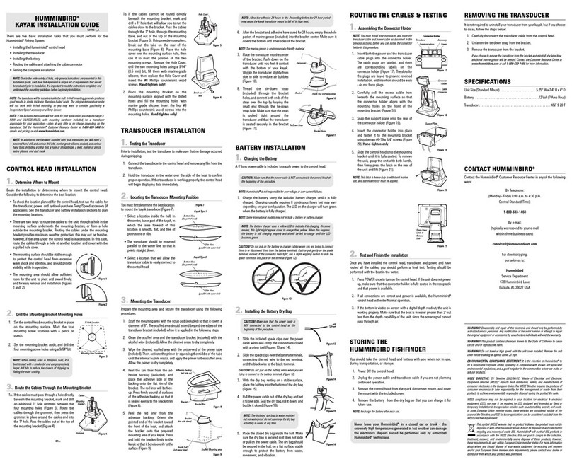
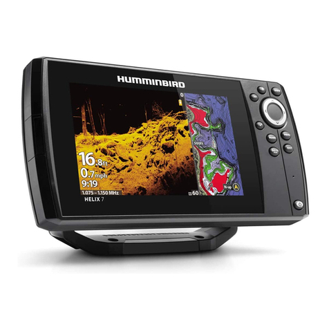
Humminbird MEGA 360 ICE ADAPTER User manual

1
MEGA 360 ICE
INSTALLATION GUIDE
532856-1EN_A

Thank You!
Thank you for choosing Humminbird®, the #1 name in marine electronics. Humminbird
has built its reputation by designing and manufacturing top-quality, thoroughly reliable
marine equipment. Your Humminbird accessory is designed for trouble-free use in
even the harshest marine environment. In the unlikely event that your Humminbird
does require repairs, we offer an exclusive Service Policy. For complete details, see
the separate warranty card included with your unit. We encourage you to read this
manual carefully in order to get the full benefit from all the features and applications
of your Humminbird product.
Contact Humminbird Technical Support by visiting our Web site at humminbird.com
or by calling 1-800-633-1468.
WARNING! This device should not be used as a navigational aid to prevent
collision, grounding, boat damage, or personal injury. When the boat is moving, water
depth may change too quickly to allow time for you to react. Always operate the boat
at very slow speeds if you suspect shallow water or submerged objects.
WARNING! The electronic chart in your Humminbird unit is an aid to navigation
designed to facilitate the use of authorized government charts, not to replace them.
Only official government charts and notices to mariners contain all of the current
information needed for the safety of navigation, and the captain is responsible for
their prudent use.
WARNING! Humminbird is not responsible for the loss of data files (waypoints,
routes, tracks, groups, recordings, etc.) that may occur due to direct or indirect
damage to the unit’s hardware or software. It is important to back up your control
head’s data files periodically. See your control head operations manual for details.
WARNING! Disassembly and repair of this electronic unit should only be
performed by authorized service personnel. Any modification of the serial number or
attempt to repair the original equipment or accessories by unauthorized individuals
will void the warranty.
NOTE: The illustrations in this manual may not look the same as your product, but
your unit will function in a similar way.
NOTE: To purchase accessories for your control head, visit our Web site at
humminbird.com or contact Humminbird Technical Support at 1-800-633-1468.
NOTE: The procedures and features described in this manual are subject to change
without notice. This manual was written in English and may have been translated to
another language. Humminbird is not responsible for incorrect translations or
discrepancies between documents.
NOTE: Product specifications and features are subject to change without notice.
NOTE: Humminbird verifies maximum stated depth in saltwater conditions, however
actual depth performance may vary due to transducer installation, water type, thermal
layers, bottom composition, and slope.
360 Imaging®, HELIX®, Humminbird®, MEGA 360 Imaging™, and X-Press™ Menu are trademarked
by or registered trademarks of Johnson Outdoors Marine Electronics, Inc.
© 2021 Johnson Outdoors Marine Electronics, Inc. All rights reserved.

i
Introduction 1
Compatibility.............................................................................. 1
Supplies................................................................................... 2
Update Software 3
Software Requirements.................................................................. 3
Check the Current Software Version .................................................... 3
Update Control Head Software with an SD Card....................................... 4
Update Accessory Software with an SD Card .......................................... 5
Update Software with FishSmart........................................................ 6
Install the MEGA 360 ICE Mount 7
1. Prepare for Installation ................................................................ 7
2. Install the MEGA 360 ICE Mount Base............................................... 7
3. Install the Handle...................................................................... 9
4. Install the Heading Sensor........................................................... 10
Route the Cables and Connect Power 12
Set Up the Control Head 14
1. Confirm Connections ................................................................. 14
2. Set Up the Transducer................................................................ 15
3. Test MEGA 360 Imaging on the Control Head ...................................... 16
4. Confirm the Heading Sensor Operation ............................................. 17
5. Add Offset Features to the MEGA 360 Imaging Display (optional) ................ 18
6. Set up the Network................................................................... 19
Stop Pinging 20
Maintenance 21
MEGA 360 Imaging Maintenance...................................................... 21
Control Head Maintenance ............................................................. 21
Transducer Maintenance ............................................................... 22
Troubleshooting 23
Fishing System Doesn’t Power Up ..................................................... 23
Fishing System Defaults to Simulator with a Transducer Attached .................. 24
Finding the Cause of Noise ............................................................. 25
Specifications 26
Contact Humminbird 28
Table of Contents Table of Contents

ii
Introduction 1
Compatibility.............................................................................. 1
Supplies................................................................................... 2
Update Software 3
Software Requirements.................................................................. 3
Check the Current Software Version .................................................... 3
Update Control Head Software with an SD Card....................................... 4
Update Accessory Software with an SD Card .......................................... 5
Update Software with FishSmart........................................................ 6
Install the MEGA 360 ICE Mount 7
1. Prepare for Installation ................................................................ 7
2. Install the MEGA 360 ICE Mount Base............................................... 7
3. Install the Handle...................................................................... 9
4. Install the Heading Sensor........................................................... 10
Route the Cables and Connect Power 12
Set Up the Control Head 14
1. Confirm Connections ................................................................. 14
2. Set Up the Transducer................................................................ 15
3. Test MEGA 360 Imaging on the Control Head ...................................... 16
4. Confirm the Heading Sensor Operation ............................................. 17
5. Add Offset Features to the MEGA 360 Imaging Display (optional) ................ 18
6. Set up the Network................................................................... 19
Stop Pinging 20
Maintenance 21
MEGA 360 Imaging Maintenance...................................................... 21
Control Head Maintenance ............................................................. 21
Transducer Maintenance ............................................................... 22
Troubleshooting 23
Fishing System Doesn’t Power Up ..................................................... 23
Fishing System Defaults to Simulator with a Transducer Attached .................. 24
Finding the Cause of Noise ............................................................. 25
Specifications 26
Contact Humminbird 28
Table of Contents Table of Contents

iii
Introduction
The MEGA 360 ICE Imaging kit provides a mounting capability to use your MEGA
360 Imaging transducer on the ice. This manual will guide you through the following
installation requirements for the MEGA 360 ICE Imaging transducer:
• Installing the MEGA 360 ICE Mount and Heading Sensor
• Connecting to the Control Head and Power
• Testing the Installation
Before proceeding with this installation, the ICE HELIX shuttle and
control head should be installed. Refer to the ICE HELIX Shuttle
Installation Guide for more information.
Compatibility
Control Heads: MEGA 360 ICE Imaging is compatible with the following Humminbird
control heads:
• HELIX MEGA Imaging+ G3N and G4N models
NOTE: You must have a GPS heading sensor (compass) installed in order to use the
MEGA 360 Imaging navigation features.
NOTE: APEX/SOLIX models are not compatible with the ICE shuttle. If you connect
a MEGA 360 ICE to an APEX/SOLIX control head, you must provide your own power
source and fuse.
NOTE: MEGA 360 Imaging can be shared with all APEX/SOLIX models and HELIX
G4N, G3N and G2N models over Ethernet.
Transducers: The MEGA 360 ICE Imaging transducer is compatible with the following
transducers:
• Dual Spectrum CHIRP ICE
• HW Dual Spectrum
• HW MEGA DI+
• HW MEGA DI+/MEGA SI+
• Built-in MEGA Imaging transducer on a Minn Kota trolling motor

1Introduction
Introduction
The MEGA 360 ICE Imaging kit provides a mounting capability to use your MEGA
360 Imaging transducer on the ice. This manual will guide you through the following
installation requirements for the MEGA 360 ICE Imaging transducer:
• Installing the MEGA 360 ICE Mount and Heading Sensor
• Connecting to the Control Head and Power
• Testing the Installation
Before proceeding with this installation, the ICE HELIX shuttle and
control head should be installed. Refer to the ICE HELIX Shuttle
Installation Guide for more information.
Compatibility
Control Heads: MEGA 360 ICE Imaging is compatible with the following Humminbird
control heads:
• HELIX MEGA Imaging+ G3N and G4N models
NOTE: You must have a GPS heading sensor (compass) installed in order to use the
MEGA 360 Imaging navigation features.
NOTE: MEGA 360 Imaging can be shared with all APEX/SOLIX models and HELIX
G4N, G3N and G2N models over Ethernet.
Transducers: The MEGA 360 ICE Imaging transducer is compatible with the following
transducers:
• Dual Spectrum CHIRP ICE
• HW Dual Spectrum
• HW MEGA DI+
• HW MEGA DI+/MEGA SI+
• Built-in MEGA Imaging transducer on a Minn Kota trolling motor

2Introduction
Update Software
Your control head model may need a software update to work with the MEGA
360 ICE Imaging transducer. We recommend that you read the following section
completely before starting any software updates.
Software Requirements
• HELIX Series: 2.180 and later
Check the Current Software Version
It is helpful to review the software version number that is currently installed on the
control head and each accessory.
1. Press and hold the VIEW key.
2. Select System > System Status.
3. Confirm the Software Version listed.
Cables: Your MEGA 360 ICE Imaging transducer comes with the cables required to
connect directly to your Humminbird fish finder. This includes a MEGA 360 ICE power
extension cable, a MEGA 360 ICE transducer extension cable, and a transducer
splitter cable (y-cable), and a heading sensor quick disconnect cable.
Accessories: For the most current list of compatible accessories, visit our Web
site at humminbird.com.
Supplies
In addition to the hardware included with your accessory, you will need the
following supplies:
• Philips head screwdriver
• Marine-grade silicone sealant (optional)
Switch: A battery switch is included with the ICE HELIX and shuttle.
Power: The MEGA 360 ICE Imaging transducer MUST be connected to a 12 VDC
power supply.

3Update Software
Update Software
Your control head model may need a software update to work with the MEGA
360 ICE Imaging transducer. We recommend that you read the following section
completely before starting any software updates.
Software Requirements
• HELIX Series: 2.180 and later
Check the Current Software Version
It is helpful to review the software version number that is currently installed on the
control head and each accessory.
1. Press and hold the VIEW key.
2. Select System > System Status.
3. Confirm the Software Version listed.
Cables: Your MEGA 360 ICE Imaging transducer comes with the cables required to
connect directly to your Humminbird fish finder. This includes a MEGA 360 ICE power
extension cable, a MEGA 360 ICE transducer extension cable, and a transducer
splitter cable (y-cable), and a heading sensor quick disconnect cable.
Accessories: For the most current list of compatible accessories, visit our Web
site at humminbird.com.
Supplies
In addition to the hardware included with your accessory, you will need the
following supplies:
• Philips head screwdriver
• Marine-grade silicone sealant (optional)
Switch: A battery switch is included with the ICE HELIX and shuttle.
Power: The MEGA 360 ICE Imaging transducer MUST be connected to a 12 VDC
power supply.

4Update Software
Update Accessory Software with an SD Card
You will need an SD or microSD card (depending on your control head model).
1. Install a formatted SD or microSD card into the computer card slot.
2. Go to humminbird.com, and click Support > Software Updates.
3. Scroll down to Accessories and Mapping. The available software updates are
listed as downloads under each accessory product. Confirm your control head
model is listed in the software description.
• Read the notices and instructions, and select Download.
• Follow the on-screen prompts to save the software file to the SD or microSD
card.
4. Power on your Humminbird control head. Start Normal mode.
5. Insert the SD or microSD card (with the software file) into the control head
card slot.
6. The software will be automatically detected. It may take up to two minutes for
the software to be detected on the network, and the control head will display
a dialog box to indicate that the update is in progress.
7. When the software update is complete, remove the SD or microSD card from
the control head card slot.
8. Restart: If you don’t have any other software updates to install, power off the
control head, and restart it.
Update Control Head Software with an SD Card
You will need an SD or microSD card (depending on your control head model).
WARNING! Humminbird is not responsible for the loss of data files (waypoints,
routes, tracks, groups, snapshots, recordings, etc.) that may occur due to direct or
indirect damage to the unit’s hardware or software. It is important to back up your
control head data files periodically. See your control head operations manual for more
information.
1. Before the control head software is updated or restored to system defaults,
export your navigation data and copy your screen snapshots to an SD or
microSD card. See your control head operations manual for instructions.
2. Install a formatted SD or microSD card into the computer card slot.
3. Go to humminbird.com, and click Support > Software Updates.
4. Click on your control head model. The available software updates are listed
as downloads under each product. Confirm the file name is for your control
head model.
• Read the notices and instructions, and select Download.
• Follow the on-screen prompts to save the software file to the SD or microSD
card.
5. Repeat step 4 to download the software updates posted to each product.
6. Power on your Humminbird control head. Start Normal mode.
7. Insert the SD or microSD card (with the software file) into the control head
card slot.
8. Follow the on-screen prompts to update the control head software.
9. When the software update is complete, remove the SD or microSD card from
the control head card slot.
10. Restart: If you don’t have any other software updates to install, power off the
control head, and restart it.

5Update Software
Update Accessory Software with an SD Card
You will need an SD or microSD card (depending on your control head model).
1. Install a formatted SD or microSD card into the computer card slot.
2. Go to humminbird.com, and click Support > Software Updates.
3. Scroll down to Accessories and Mapping. The available software updates are
listed as downloads under each accessory product. Confirm your control head
model is listed in the software description.
• Read the notices and instructions, and select Download.
• Follow the on-screen prompts to save the software file to the SD or microSD
card.
4. Power on your Humminbird control head. Start Normal mode.
5. Insert the SD or microSD card (with the software file) into the control head
card slot.
6. The software will be automatically detected. It may take up to two minutes for
the software to be detected on the network, and the control head will display
a dialog box to indicate that the update is in progress.
7. When the software update is complete, remove the SD or microSD card from
the control head card slot.
8. Restart: If you don’t have any other software updates to install, power off the
control head, and restart it.
Update Control Head Software with an SD Card
You will need an SD or microSD card (depending on your control head model).
WARNING! Humminbird is not responsible for the loss of data files (waypoints,
routes, tracks, groups, snapshots, recordings, etc.) that may occur due to direct or
indirect damage to the unit’s hardware or software. It is important to back up your
control head data files periodically. See your control head operations manual for more
information.
1. Before the control head software is updated or restored to system defaults,
export your navigation data and copy your screen snapshots to an SD or
microSD card. See your control head operations manual for instructions.
2. Install a formatted SD or microSD card into the computer card slot.
3. Go to humminbird.com, and click Support > Software Updates.
4. Click on your control head model. The available software updates are listed
as downloads under each product. Confirm the file name is for your control
head model.
• Read the notices and instructions, and select Download.
• Follow the on-screen prompts to save the software file to the SD or microSD
card.
5. Repeat step 4 to download the software updates posted to each product.
6. Power on your Humminbird control head. Start Normal mode.
7. Insert the SD or microSD card (with the software file) into the control head
card slot.
8. Follow the on-screen prompts to update the control head software.
9. When the software update is complete, remove the SD or microSD card from
the control head card slot.
10. Restart: If you don’t have any other software updates to install, power off the
control head, and restart it.

6Update Software
Install the MEGA 360 ICE Mount
Use the following instructions to install the MEGA 360 Imaging ICE transducer
mount. It is important to read the instructions completely and understand the
mounting guidelines before you start the installation.
1. Prepare for Installation
1. Supplies: Philips screwdriver.
2. Complete the ICE HELIX Series Shuttle installation before proceeding with
this installation.
3. When the transducer pod is in use, the pod should be completely submerged
below the ice. The transducer pod should not have anything obstructing
the ‘view’ of the rotating beams. If the beams are blocked, confirm that the
transducer is below the ice and move other equipment, such as additional
transducers, if possible.
2. Install the MEGA 360 ICE Mount Base
Use the following instructions to install the MEGA 360 ICE mounting assembly:
1. Slide the cam lock over the MEGA 360 cables and down the pod shaft.
2. Determine the desired height for the ice base, depending on the thickness of
the ice, and close the lever arm to lock the cam lock into position.
NOTE: The MEGA 360 pod must be submerged below the ice.
3. From the bottom of the ice base, insert the round, black bushing into the
center of the base. You will hear it snap into place.
4. From the top of the ice base, line up the collet with the keyed grooves in the
base and slide it into place.
Update Software with FishSmart
You can use the FishSmart App to download and push software updates directly to
your Humminbird control head or accessory.
NOTE: Your control head must already be running software release 1.610 and later
to support this feature.
NOTE: You must first download the FishSmart App and pair your mobile device to
your control head. See the FishSmart User Manual for more information.
1. Open the FishSmart App on your mobile device.
2. Apple iOS: Tap the System menu icon.
Google Android: Tap the FishSmart main menu. Select system.
3. Tap Update next to the selected unit. The download progress is displayed on
the screen.
4. Tap Transfer next to the selected unit once the download is complete.
5. Confirm the estimated transfer time.
6. Tap the checkbox to select where to upload the software update (internal
storage, card slot 1, or card slot 2).
7. Tap Transfer. The upload progress is displayed on the System menu in
FishSmart and in the System Status view on the control head.
8. Follow the on-screen prompts on the control head to complete the software
installation.

7Installing the ICE Mount
Install the MEGA 360 ICE Mount
Use the following instructions to install the MEGA 360 Imaging ICE transducer
mount. It is important to read the instructions completely and understand the
mounting guidelines before you start the installation.
1. Prepare for Installation
1. Supplies: Philips screwdriver.
2. Complete the ICE HELIX Series Shuttle installation before proceeding with
this installation.
3. When the transducer pod is in use, the pod should be completely submerged
below the ice. The transducer pod should not have anything obstructing
the ‘view’ of the rotating beams. If the beams are blocked, confirm that the
transducer is below the ice and move other equipment, such as additional
transducers, if possible.
2. Install the MEGA 360 ICE Mount Base
Use the following instructions to install the MEGA 360 ICE mounting assembly:
1. Slide the cam lock over the MEGA 360 cables and down the pod shaft.
2. Determine the desired height for the ice base, depending on the thickness of
the ice, and close the lever arm to lock the cam lock into position.
NOTE: The MEGA 360 pod must be submerged below the ice.
3. From the bottom of the ice base, insert the round, black bushing into the
center of the base. You will hear it snap into place.
4. From the top of the ice base, line up the collet with the keyed grooves in the
base and slide it into place.
Update Software with FishSmart
You can use the FishSmart App to download and push software updates directly to
your Humminbird control head or accessory.
NOTE: Your control head must already be running software release 1.610 and later
to support this feature.
NOTE: You must first download the FishSmart App and pair your mobile device to
your control head. See the FishSmart User Manual for more information.
1. Open the FishSmart App on your mobile device.
2. Apple iOS: Tap the System menu icon.
Google Android: Tap the FishSmart main menu. Select system.
3. Tap Update next to the selected unit. The download progress is displayed on
the screen.
4. Tap Transfer next to the selected unit once the download is complete.
5. Confirm the estimated transfer time.
6. Tap the checkbox to select where to upload the software update (internal
storage, card slot 1, or card slot 2).
7. Tap Transfer. The upload progress is displayed on the System menu in
FishSmart and in the System Status view on the control head.
8. Follow the on-screen prompts on the control head to complete the software
installation.

8Installing the ICE Mount
7. Twist to tighten the knob over the collet on the ice base.
Adjust the height of the ice base as needed.
3. Install the Handle
1. Push the nut out of the depth collar.
2. Thread the MEGA 360 cables up through the depth collar and slide the depth
collar down the shaft to the desired height.
3. Place the bolt through the counterbore hole in the depth collar and screw on
the handle. Hand-tighten only!
TIP: Orient the handle so it is parallel with the front of the transducer.
rounded part
of transducer
Aligning the Transducer
Assembling the Base
5. Thread the MEGA 360 cables up through the ice base, and slide the ice base
down the pod shaft. It will rest on the cam lock.
6. Thread the MEGA 360 cables up through the knob and slide the knob down
the pod shaft.
Attaching the Knob

9Installing the ICE Mount
7. Twist to tighten the knob over the collet on the ice base.
Adjust the height of the ice base as needed.
3. Install the Handle
1. Push the nut out of the depth collar.
2. Thread the MEGA 360 cables up through the depth collar and slide the depth
collar down the shaft to the desired height.
3. Place the bolt through the counterbore hole in the depth collar and screw on
the handle. Hand-tighten only!
TIP: Orient the handle so it is parallel with the front of the transducer.
rounded part
of transducer
Aligning the Transducer
Assembling the Base
5. Thread the MEGA 360 cables up through the ice base, and slide the ice base
down the pod shaft. It will rest on the cam lock.
6. Thread the MEGA 360 cables up through the knob and slide the knob down
the pod shaft.
Attaching the Knob

10Installing the ICE Mount
Fully Assembled MEGA 360 ICE
4. Install the Heading Sensor
1. Thread the MEGA 360 cables up through the heading sensor mount.
2. Position the heading sensor mount at the top of the pod shaft.
3. The mount should be aligned so the opening for the cables is toward the back
of the MEGA 360 Imaging pod.
4. Secure the heading sensor mount with one 1/4 - 20 screw and one 1/4 - 20
hex nut through the stem.
5. Route the MEGA 360 cables through the opening of the heading sensor
mount and hold them in place.
6. Position the sensor so that the arrow on the cover is parallel with the front of
the transducer (rounded part).
7. Attach the heading sensor to its base using the two #8 - 32 x 1 1/4" screws
and two #8 -32 hex nuts.
NOTE: Failure to align the sensor correctly will result in incorrect compass readings.
Installing the Heading Sensor

11 Installing the ICE Mount
Fully Assembled MEGA 360 ICE
4. Install the Heading Sensor
1. Thread the MEGA 360 cables up through the heading sensor mount.
2. Position the heading sensor mount at the top of the pod shaft.
3. The mount should be aligned so the opening for the cables is toward the back
of the MEGA 360 Imaging pod.
4. Secure the heading sensor mount with one 1/4 - 20 screw and one 1/4 - 20
hex nut through the stem.
5. Route the MEGA 360 cables through the opening of the heading sensor
mount and hold them in place.
6. Position the sensor so that the arrow on the cover is parallel with the front of
the transducer (rounded part).
7. Attach the heading sensor to its base using the two #8 - 32 x 1 1/4" screws
and two #8 -32 hex nuts.
NOTE: Failure to align the sensor correctly will result in incorrect compass readings.
Installing the Heading Sensor

12Cable Installation
4. Connect one end of the MEGA 360 ICE sonar extension cable to the MEGA
360 ICE sonar Y-cable and connect the other end to the sonar cable connector
on the MEGA 360 ICE pod shaft.
5. Connect the heading sensor cable to the heading sensor quick disconnect
cable.
6. Cable Management: Wrap excess cable using the molded hooks on the
MEGA 360 ICE adapter base.
NOTE: The connectors are keyed to prevent reversed installation, so be careful not
to force the connectors. Hand-tighten the screw nuts on each connector.
NOTE: Secure the cables with cable ties along the route as needed for a clean
assembly.
Route the Cables and Connect Power
The MEGA 360 ICE transducer comes with quick disconnect cables so that you can
quickly and easily disconnect your MEGA 360 ICE transducer from your ICE HELIX
control head and shuttle.
WARNING! The power source must be turned off before you proceed with this
installation.
WARNING! The MEGA 360 Imaging transducer should be connected to a battery
switch and 1 amp fuse.
NOTE: See the ICE HELIX Installation Guide for more information about connecting
the battery, the power switch and the HELIX cable tray.
1. Route the MEGA 360 ICE sonar Y-cable and heading sensor quick disconnect
cable to the HELIX cable tray.
See the ICE HELIX Installation Guide for more information about routing
cables to the cable tray.
NOTE: If you have an ice transducer installed, you must disconnect it from
the HELIX sonar port and connect it to the MEGA 360 ICE sonar Y-cable.
HELIX 8, 9, 10, 12 Cable Tray
Ethernet temp/speedpin pin
power
COM (communications)
transducer
2. Route the other end of the MEGA 360 ICE sonar Y-cable, heading sensor quick
disconnect cable and one SAE port from the power backbone through the
side grommet on the shuttle.
3. Connect one end of the MEGA 360 ICE power extension cable to the SAE port
and connect the other end to the power cable connector on the MEGA 360
ICE pod shaft.

13 Cable Installation
4. Connect one end of the MEGA 360 ICE sonar extension cable to the MEGA
360 ICE sonar Y-cable and connect the other end to the sonar cable connector
on the MEGA 360 ICE pod shaft.
5. Connect the heading sensor cable to the heading sensor quick disconnect
cable.
6. Cable Management: Wrap excess cable using the molded hooks on the
MEGA 360 ICE adapter base.
NOTE: The connectors are keyed to prevent reversed installation, so be careful not
to force the connectors. Hand-tighten the screw nuts on each connector.
NOTE: Secure the cables with cable ties along the route as needed for a clean
assembly.
Route the Cables and Connect Power
The MEGA 360 ICE transducer comes with quick disconnect cables so that you can
quickly and easily disconnect your MEGA 360 ICE transducer from your ICE HELIX
control head and shuttle.
WARNING! The power source must be turned off before you proceed with this
installation.
WARNING! The MEGA 360 Imaging transducer should be connected to a battery
switch and 1 amp fuse.
NOTE: See the ICE HELIX Installation Guide for more information about connecting
the battery, the power switch and the HELIX cable tray.
1. Route the MEGA 360 ICE sonar Y-cable and heading sensor quick disconnect
cable to the HELIX cable tray.
See the ICE HELIX Installation Guide for more information about routing
cables to the cable tray.
NOTE: If you have an ice transducer installed, you must disconnect it from
the HELIX sonar port and connect it to the MEGA 360 ICE sonar Y-cable.
HELIX 8, 9, 10, 12 Cable Tray
Ethernet temp/speedpin pin
power
COM (communications)
transducer
2. Route the other end of the MEGA 360 ICE sonar Y-cable, heading sensor quick
disconnect cable and one SAE port from the power backbone through the
side grommet on the shuttle.
3. Connect one end of the MEGA 360 ICE power extension cable to the SAE port
and connect the other end to the power cable connector on the MEGA 360
ICE pod shaft.

14Control Head Setup
2. Set Up the Transducer
Use the following instructions to select the connected transducer for your control
head. These steps are only required the first time you set up your HELIX control head
with a new transducer.
1. Main Menu: Press the Menu key twice.
2. Select the Sonar tab > Connected Transducer.
3. Press the RIGHT or LEFT Cursor keys to scroll through the compatible
transducers. Select the transducer that is attached to the control head.
Selecting the Connected Transducer
Set Up the Control Head
When the control head detects the MEGA 360 Imaging transducer, it will select it
automatically as the 360 sonar source. The related views and menus will be added
to the system.
Use the following instructions to power on the control head and confirm the MEGA
360 Imaging transducer is detected by the unit.
CAUTION! It is important to finish all installation connections before powering on
the control head.
1. Confirm Connections
1. Turn on the power source from the main switch.
2. On the control head, press the POWER key. If you are powering on a control
head in a multiple-control head Ethernet network, power on the control
head that is connected to the MEGA 360 Imaging transducer first.
3. When the Title screen is displayed, press the MENU key.
4. Select Normal. Press the RIGHT Cursor key.
5. Press and hold the VIEW key. Select System > Accessory Test. Confirm that
MEGA 360 Imaging is listed as Connected.
MEGA 360
Imaging listed
as Connected
HELIX Accessory Test
NOTE: If the Accessory Test is not displayed in the View Rotation, press the
MENU key twice to open the Main Menu. Select the Views tab > Accessory
Test. Change the setting to Visible.
Other manuals for MEGA 360 ICE ADAPTER
1
Table of contents
Other Humminbird Fishing Equipment manuals
Popular Fishing Equipment manuals by other brands

Jiffy
Jiffy 56 Operating manual/parts guide

Fox
Fox Mini Micron user guide

Innova
Innova iTroll Generation 2 owner's manual

Scotty
Scotty LINE PULLER Installation, Maintenance, Use and Safety

Bass Pro Shops
Bass Pro Shops Revolution RNC300H instructions

Classic Accessories
Classic Accessories Gunnison Float Tube instructions