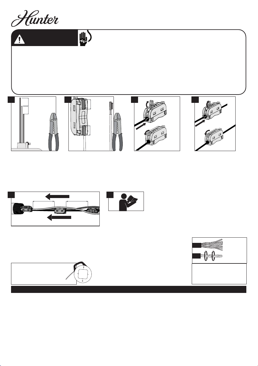
Siempre mantenga los conectores separados por aproximadamente
76 mm (3 pulgadas) al insertar los alambres dentro del tubo de
soporte tal como se muestra en la imagen. Pase todos los alambres
a un lado de la barra horizontal en el conjunto de tubo de soporte.
Recuerde mover el alambre de puesta a tierra desde el tubo de
soporte suministrado al tubo de soporte nuevo.(Vea la imagen 5).
Kit de alambres de extensión de 1,5 m (60 pulg.) - Modelo 99779
x3 x3
Hunter Fan Company crea la siguiente garantía limitada para el com-prador original de este accesorio (“Accesorio”): Garantizamos durante un año
a partir de la fecha de compra que su accesorio no tendrá defectos en materiales ni mano de obra.Si el Accesorio presenta un funcionamiento
defectuoso o una avería dentro del período de garantía debido a un defecto en el material o la mano de obra,lo reemplazaremos en forma
gratuita. SI EL COMPRADOR ORIGINALDEJADE POSEER EL ACCESORIO, ESTA GARANTÍA YCUALQUIER GARANTÍA IMPLÍCITA,IN-CLUYENDO, ENTRE
OTRASTODA GARANTÍA IMPLÍCITA DE COMERCIABILIDAD O IDONEIDAD PARA UN PROPÓSITO ESPECÍFICO, QUEDA ANULADA. ESTA GARANTÍA
SUSTITUYE ATODAS LAS OTRAS GARANTÍAS EXPRESAS. LA DURACIÓN DETODA GAR-ANTÍAIMPLÍCITA, INCLUYENDO ENTRE OTRAS CUALQUIER
GARANTÍA IMPLÍCITA DE COMERCIABILIDAD O IDONEIDAD PARA UN PROPÓSITO ESPECÍFICO, RELACIONA-DACON CUALQUIER ACCESORIO, ESTÁ
EXPRESAMENTE LIMITADA AL PERÍODO DE LA GARANTÍAEXPRESA ESTABLECIDA ANTERIORMENTE PARA DICHO ACCESORIO. Esta garantía excluye
funcionamientos defectuosos o fallas causados por repara-ciones realizadas por personas no autorizadas por nosotros,por mal uso, in-stalación
incorrecta, modicaciones, o daños al Accesorio mientras esté en su posesión, o por uso no razonable. EN NINGÚN CASO HUNTER FAN COMPANY
SERÁ RESPONSABLE DE DAÑOS PERJUDICIALES O ACCESORIOS.ALGUNOS ESTADOS NO PERMITEN LIMITACIONES SOBRE LA DURACIÓN DE UNA
GARANTÍA IMPLÍCITA O LA EXCLUSIÓN O LIMITACIÓN DE DAÑOS ACCESORIOS O PERJUDICIALES,ASÍ QUE LA LIMITACIONES O EXCLUSIONES
ANTES MENCIONADAS PUEDEN NOAPLICARSEA USTED. ESTA GARANTÍA LE DA DERECHOS LEGALES ESPECÍFICOS,PERO USTED TAMBIÉN PUEDE
TENER OTROS DERECHOS QUEVARÍAN DE ESTADO AESTADO.
3 pulg
(76 mm)
3 pulg
(76 mm)
3 pulg
(76 mm)
3 pulg
(76 mm)
3/8 pulg
(9 mm)
3/8 pulg
(9 mm)
Utilice cortadores de alambre
para cortar cada alambre del
ventilador. Las longitudes de los
tres alambres se deben escalonar
al menos 76 mm (3 pulgadas)
para permitir que los conectores
se inserten más fácilmente
dentro del tubo de soporte.
Pele 9 mm (3/8 de pulgada)
de aislamiento de los
alambres del ventilador.
Utilice la guía en la parte
trasera del conector para la
referencia de 9 mm
(3/8 de pulgada).
Para abrir,levante la
palanca del conector hasta
la posición totalmente
vertical. Inserte el alambre
pelado y asegúrelo bajando
la palanca. Verique que
no quede expuesto ningún
alambre desnudo o sin
aislamiento.Repita para los
alambres restantes.
Remueva el aislamiento
precortado de cada alambre
de extensión. Para abrir,
levante la palanca opuesta
del conector hasta la
posición totalmente vertical.
Inserte el alambre de
extensión pelado del mismo
color y asegúrelo bajando
la palanca. Verique que
no quede expuesto ningún
alambre desnudo o sin
aislamiento.Repita para los
alambres restantes.
Consulte el manual
de instalación de su
ventilador para conectar
el tubo de soporte al
ventilador y para apretar
con pinzas el tornillo de
jación para asegurar el
tubo de soporte antes
de colgar el ventilador y
conectar los alambres.
• Para evitar posibles choques eléctricos, antes de instalar o dar servicio de mantenimiento a su
ventilador, desconecte el suministro de energía apagando los interruptores automáticos que
alimentan la caja de salida y el interruptor de pared asociado. Si usted no puede bloquear los
interruptores automáticos en la posición de apagado, asegure rmemente una forma destacada de
advertencia, como una etiqueta de seguridad, en el tablero de servicio.
• Todo el cableado se debe realizar de acuerdo con los códigos eléctricos locales y nacionales ANSI/
NFPA 70. Si usted no está familiarizado con el cableado o tiene dudas, consulte a un electricista
calicado.
• El ventilador de techo se debe conectar a tierra. Si el alambre de conexión a tierra no está presente
en el sitio de la instalación, DETENGA inmediatamente la instalación y consulte con un electricista
calicado.
GARANTÍA LIMITADA DEL ACCESORIO DE HUNTER FAN COMPANY
NOTA: Se recomienda la cinta pasa-alambres (Fishtape) para
pasar los alambres de extensión y los conectores a través del
tubo de soporte.
1 2 3 4
5
6
NOTA: Retuerza las
trenzas de alambres antes
de insertarlas dentro del
puerto del conector para
cada cable.