Hunter Tea Stain Bowl Light Kit User manual

Tea Stain Bowl Light Kit
Installation Instructions
43536-01 r111407

IMPORTANT: Read all warnings before you begin.
CAUTIONS
• Readentireinstallationinstructionscarefullybeforebeginninginstallationandsavetheseinstructions.
• Toavoidpossibleriskofelectricalshockandfire,installthislightfixtureonlyonHunterceilingfanType
A-Z.Findthefanmodelnumberonthefanpackageoronthenameplateontopofthemotorhousing.
WARNINGS
• Toavoidpossibleelectricalshock,beforeinstallinglightfixturedisconnectpowerbyturningoffthe
circuitbreakersbothtotheoutletboxandtoitsassociatedwallswitchlocation.If
youcannotlockthecircuitbreakersintheoffposition,securelyfastenaprominent
warningdevice,suchasatag,totheservicepanel.
• Connecthousewiringtothefanbeforeattachingthelightfixturetothefan.
• Allwiringmustbeinaccordancewithnationalandlocalelectricalcodes.Ifyouare
unfamiliarwithwiring,youshoulduseaqualifiedelectrician.Professionalinstallationisrecommended.
• Toreducetheriskoffireorpersonalinjury,allowbulbsandsurroundingsurfacestocooltoroom
temperaturebeforetouchingorremovingthem.
is light fixture is for use only on Hunter Ceiling Fans Type A-Z.
OI
is light fixture weighs 3.66 pounds.
ismanualcontainsinstallationinstructionsforthefollowingtypesoffans:
• FansWithRemovableSwitchHousing
• FansWithNon-RemovableSwitchHousing
• FansWithNon-RemovableSwitchHousingandNoCenterHole
PreparingtheInstallationSite
1. Disconnectpowerbyturningothecircuitbreakersbothtotheoutletboxandtoitsassociatedwallswitch
location.
43536-01 r1114072

InstallingtheLightKitonFansWithRemovableSwitchHousing
1. Unscrewthethreescrewsfromtheupperswitchhousing.
Disconnectthe9-pinplugconnectors.Removethelowerswitch
housing.
2. Pushtheplugfrominsidethelowerswitchhousingtoremovetheplugand
switchhousingcap.
NOTE:Savetheplugbuttonandswitchhousingcapshouldyouchooseto
removethelightxtureinthefuture.
CAUTION:Ifyourfanisoperatedbyremotecontrol,takecarenottodamage
thesmallcomponentsonthecircuitboardinsidethehousing.
3. Screwthethreadedrodoftheupperlighthousingintothecenterofthelower
switchhousinguntilyoufeelresistance.Unscrewtheupperlighthousingslightly
until the holes of the upper light housing are aligned with the holes in the lower
switchhousing.
4. Finishattachingtheupperlighthousingtothelowerswitchhousingusingthe
twoattachmentscrewsincluded.Securelytightenthetwoscrews.
5. Installthenutandwasherinsidetheupperswitchhousingontothethreaded
rodfromtheupperlighthousing.
6. Feedthetwowiresfromthelightkitupthroughthecenterholeinthelower
switchhousing.
7. Attachthelightkittotheupperlighthousingbypartiallyinstallingtwoscrews
intheupperlighthousing.Alignthekeyholeslotsinthelightkitwiththe
preinstalledscrews.Turnthelightkitclockwiseuntilthehousingassembly
screwsarermlysituatedinthenarrowendofthekeyholeslots.Installathird
screwintotheupperlighthousing.Tightenallthreescrewsrmly.
OI
RemovableSwitchHousing
9-PinPlug
Connector
LowerSwitch
Housing
LowerSwitch
Housing
Upper Light
Housing
Light Kit
Plug
Attachment
Screw
Screw
43536-01 r111407 3
Steps 1–2
Steps 3-7
Screw

8. Removethewireconnectorsfromthetwowiresintheswitch
housinglabeled“ConnectLightHere”or“ForLightUse.”
Toconnectthewires,holdthebaremetalleadstogetherandplacea
wireconnectoroverthem,thentwistthewireconnectorclockwise
until tight.
Connecttheblack/whitestripedwirefromtheswitchhousingtotheblackwire
fromthelightkit.Connectthewhitewirefromtheswitchhousingtothewhite
wirefromthelightkit.Secureallwireconnectionsusingwireconnectors.
CAUTION:Besurenobaremetalwiresorwirestrandsarevisibleaftermaking
theconnections.
9. Reconnectthe9-pinplugconnector.
10. Installscrewstoreattachthelowerswitchhousingtotheupperswitchhousing.
11. GototheinstructionsforInstallingtheBulbs,Chains,andGlobe.
OI
43536-01 r111407 4
Steps 8-10
Wires
andWire
connectors

InstallingtheLightKitonFansWithNon-Removable
SwitchHousing
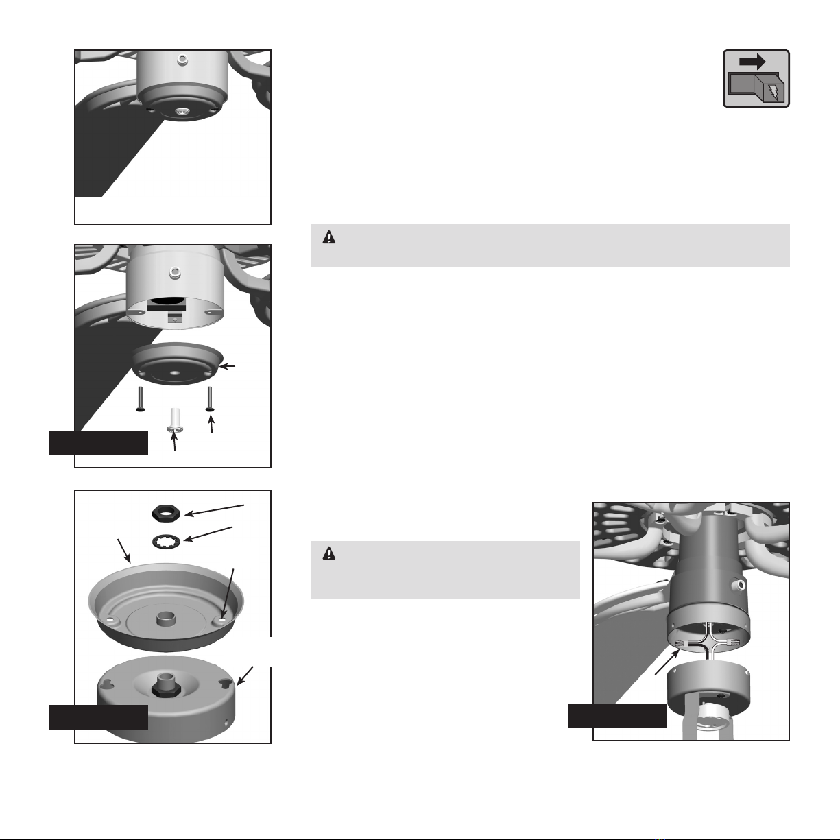
1. Uninstallthetwoscrewsfromtheswitchhousingcover.
2. Removetheplugorscrewfromthecenteroftheswitchhousing
cover.
3. readtheswitchhousingcoverontotheupperlighthousing.Alignthescrew
holesintheupperlighthousingwiththescrewholesintheswitchhousingcover.
Installthenutandwasherontothethreadedrodfromthelightkittosecurethe
switchhousingcover.
WARNING:Improperinstallationcouldcausethelightxturetofall,orresult
inelectricalshockorpersonalinjury.
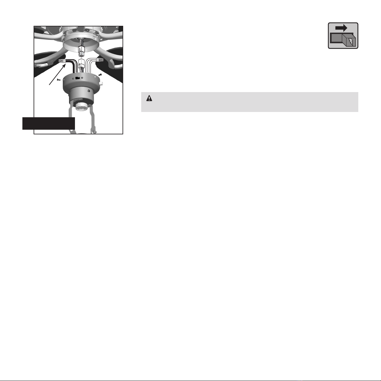
4. Removethewireconnectorsfromthetwowiresintheswitchhousinglabeled
“ConnectLightHere”or“ForLightUse.”Onewireiswhiteandtheotherwireis
black/whitestriped.
5. Feedthetwowiresfromtheswitchhousingthroughthethreadedrodinthe
upper light housing.
6. Alignthethreadedscrewholesintheswitchhousingcoverwiththethreaded
holesintheswitchhousing.Attachtheswitchhousingcoverandupperlight
housingassemblytotheswitchhousingusingtheincludedattachmentscrews.
7. Toconnectthewires,holdthebaremetalleadstogetherandplaceawire
connectoroverthem,thentwistthewireconnectorclockwiseuntiltight.
Connecttheblack/whitestripedwirefromtheswitchhousingtotheblack
wirefromthelightkit.Connectthewhitewirefromtheswitchhousingtothe
whitewirefromthelightkit.Secureallwire
connectionsusingwireconnectors.
CAUTION:Besurenobaremetalwires
orwirestrandsarevisibleaftermakingthe
connections.
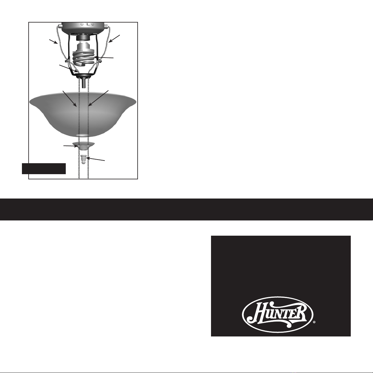
8. Finishattachingthelightkitbypartially
installingtwoscrewsintheupperlight
housing.Alignthekeyholeslotsinthe
lightkitwiththepreinstalledscrews.Turn
thelightkitclockwiseuntilthehousing
assemblyscrewsarermlysituatedinthe
narrowendofthekeyholeslots.Installa
thirdscrewintotheupperlighthousing.
Tightenallthreescrewsrmly.
9. GototheinstructionsforInstallingtheBulbs,Chains,andGlobe.
OI
Steps 1–2
Step 3 Step 7
Non-RemovableSwitchHousing
withCenterHole
Switch
Housing
Cover
Plug
Nut
Washer
Screw
Hole
Switch
Housing
Cover
Wires
andWire
connectors
Attachment
Screw
43536-01 r1114075
Upper Light
Housing

InstallingtheLightKitonFansWithNon-RemovableSwitch
HousingandNoCenterHole
1. Uninstallthetwoscrewsfromtheswitchhousingplate.
2. Removethewireconnectorsfromthetwowiresintheswitch
housinglabeled“ConnectLightHere”or“ForLightUse.”Onewireiswhiteand
theotherwireisblack/whitestriped.readthetwowiresthroughtheholein
thecenteroftheupperlighthousing.
3. Alignthescrewholesintheupperlighthousingwiththescrewholesinthe
switchhousing.Installtheupperlighthousingtotheswitchhousingusingthe
twoattachmentscrewsprovided.
4. Toconnectthewires,holdthebaremetalleadstogetherandplaceawire
connectoroverthem,thentwistthewireconnectorclockwiseuntiltight.
Connecttheblack/whitestripedwirefromtheswitchhousingtotheblackwire
fromthelightkit.Connectthewhitewirefromtheswitchhousingtothewhite
wirefromthelightkit.Secureallwireconnectionsusingwireconnectors.
CAUTION:Besurenobaremetalwiresorwirestrandsarevisibleaftermaking
theconnections.
5. Attachthelightkittotheupperlighthousingbypartiallyinstallingtwoscrews
intheupperlighthousing.Alignthekeyholeslotsinthelightkitwiththe
preinstalledscrews.Turnthelightkitclockwiseuntilthehousingassembly
screwsarermlysituatedinthenarrowendofthekeyholeslots.Installathird
screwintotheupperlighthousing.Tightenallthreescrewsrmly.
WARNING:Improperinstallationcould
causethelightxturetofall,orresultin
electricalshockorpersonalinjury.
6. GototheinstructionsforInstallingthe
Bulbs,Chains,andGlobe.
OI
Hunteroriginalandnon-
removableswitch,nocenterhole
Step 1
Switch
Housing
Plate
Screw
43536-01 r111407 6
Step 4
Steps 2-3
WiresandWire
Connectors
Attachment
Screws
Upper Light
Housing

Hunter Fan Company
2500 Frisco Avenue
Memphis,Tennessee 38114
Printed in China©2007HunterFanCompany
Troubleshooting
Lightdoesnotcomeon.
1. Makesurebulbsareinstalledproperlyandlamentisnotblown.
2. Makesurebreakersorfusesareon.
3. Verifythatthelightpowerleadisconnectedattheceiling.Refer
toyourceilingfanmanualforlocatingassemblyandwiring.
Glassrattles.
1. Makesuretheglassglobeissecure.
Forotherproblemsorquestions,contactthe
HunterFanCompanyTechnicalSupportat
US888-830-1326/Canada866-268-1936.
http://www.hunterfan.com
InstallingtheBulbs,Chains,andGlobe
1. Attachtheextrapullchain(included)tothefanpullchainusingthe
plasticbreakawayconnector.(Youmayndtheplasticbreakaway
connectorontheendoftheextrachain.)
2. Feedthefanandlightpullchainsasshown.
3. Install the Pin-Based CFL(18WattMaximum)bulb into the socket.
4. Placethecoverplateupagainsttheglassbowl.Aligntheholesinthe
coverplatewiththegrommetholeofthemetaldisc.
5. Screwthenialontothethreadedrodenduntiltight.
6. einstallationiscompleteandyoucanrestorepowertotheceilingfan.
43536-01 r1114077
Steps 1–5
Grommet
Hole
(MetalDisc)
Fan Pull
Chain
Fan Pull
Chain
Light Pull
Chain
Light Pull
Chain
Bulb
Hole
(CoverPlate)
Finial
Table of contents
Other Hunter Home Lighting manuals

Hunter
Hunter Bullet Spotlight Kit Instruction manual

Hunter
Hunter Floating Glass Light Kit User manual

Hunter
Hunter Casbah Light Kit User manual

Hunter
Hunter Dual Function Bowl Light Kit Instruction manual

Hunter
Hunter 10” User manual

Hunter
Hunter Tribeca Light Kit Tribeca Light Kit Instruction manual

Hunter
Hunter MM288PU Owner's manual

Hunter
Hunter Marine II Instruction manual
Popular Home Lighting manuals by other brands

MELINERA
MELINERA HG01313 Operation and safety notes

Dainolite
Dainolite DLHA102 Important safety instructions

Maretti
Maretti PIETBOON STACK WALL E27 quick start guide

Philips
Philips SmartSpot 69078/31/16 brochure

Philips
Philips ecomoods 40340/48/16 user manual

hudson valley
hudson valley L1297 installation instructions