English –7
SAFETY INSTRUCTIONS
General safety instructions
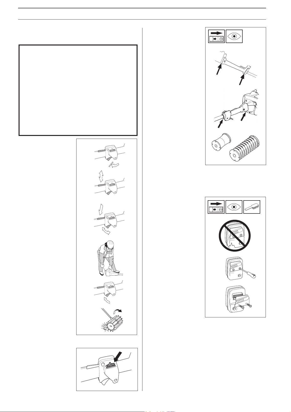
Transport and storage
•Store and transport the machine and fuel so that any leakage
or fumes do not risk coming into contact with sparks or
naked flames. For example, electric machines, electric
motors, electrical switches/power switches, heaters or the
like.
•When storing and transporting fuel approved containers
intended for this purpose must be used.
•When storing the machine for long periods the fuel tank
must be emptied. Contact your local petrol station to find
out how to dispose of excess fuel.
Fuel safety
•Always use a fuel container
with an anti-spill valve.
•Never fill the machine while
the engine is running.
Always stop the engine and
let it cool for a few minutes
before refuelling.
•Provide good ventilation
when filling or mixing fuel
(petrol and 2-stroke oil).
•Move the machine at least 3
m from the filling position
before starting.
•Never start the machine:
a)If you have spilt fuel on it.
Wipe up all spillage.
b)If you have spilt fuel on
yourself or your clothes.
Change your clothes.
c)If there is a fuel leak. Make
regular checks for leakage
from the fuel cap and the
fuel supply pipes.
Min. 3 m
(10 ft)
IMPORTANT INFORMATION
• The machine is only designed for sweeping lawns,
pathways, asphalt roads and the like.
• Never use the machine if you are tired, if you
have consumed alcohol, or if you are taking
medicines that can affect your sight, your
judgement or the control of your body.
• Use personal protective equipment. See the
section
“Personal protective equipment“.
•Never use a machine that has been modified so
that it no longer corresponds with the original
design.
•Never use a machine that is faulty. Follow the
maintenance, control and service instructions in
this Operator‘s Manual. Some maintenance and
service actions should be carried out by trained
and qualified specialists. See the chapter
“Maintenance“
.
•All covers must be fitted before starting the
machine. Check that the spark plug cap and HT
lead are not damaged, otherwise you could get an
electric shock.
•The machine operator shall ensure, while
working, that no persons or animals come closer
than 15 metres (50 feet). When several operators
are working in the same area the safety distance
should be at least double tree length, however, at
least 15 metres (50 feet).
•The complete clutch cover with shaft must be fitted before
the machine is started, otherwise the clutch can become
loose and cause personal injury.
•Never start the machine indoors. Bear in mind the dangers
of inhaling the engine‘s exhaust fumes.
•Observe your surroundings and make sure that there is no
risk of people or animals coming into contact with the
sweeper rollers.
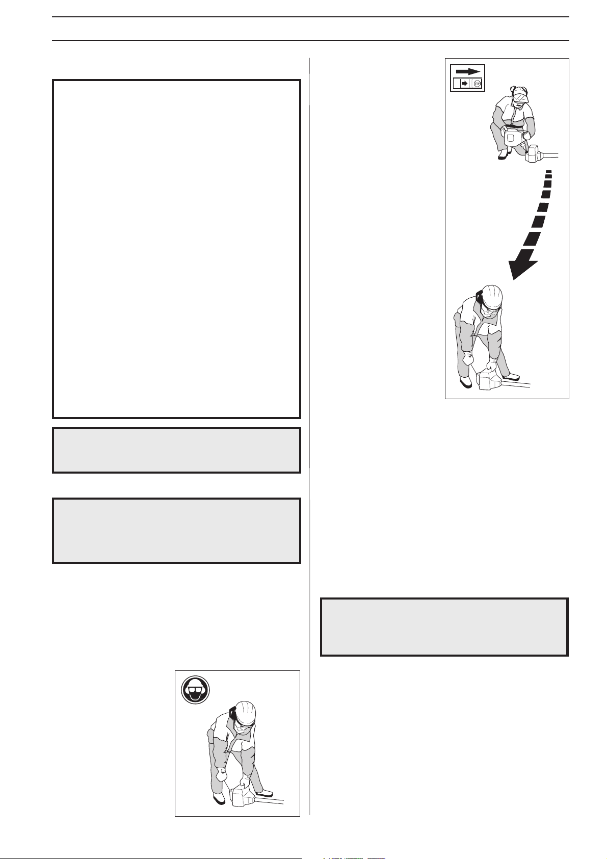
•Place the machine on the
ground, ensure the sweeper
rollers runs free of twigs
and stones. Push the
machine body towards the
ground using your left
hand. (NOTE! Not with
your foot). Grip the starter
handle with your right
hand and pull the
startercord.
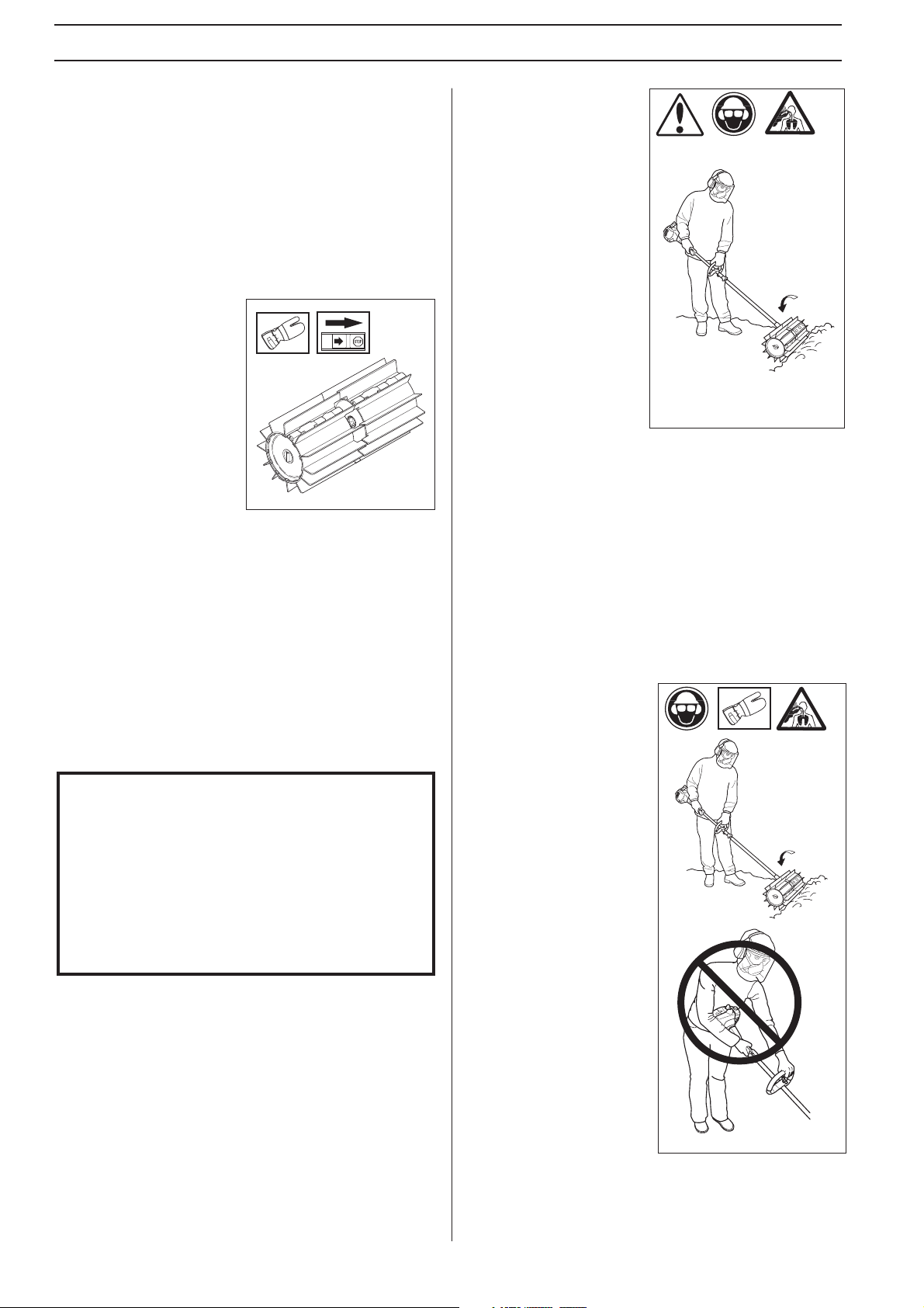
!WARNING!
When the engine is started with the choke
in either the choke or start throttle positions
the sweeper rollers starts to rotate
immediately.
WARNING!
Exercise great care when handling fuel.
Bear in mind the risk of fire, explosions and
inhaling fumes.
!
Start
WARNING!
Faulty equipment increases the risk of
accidents.
!
Safety instructions regarding the
surroundings
•Never allow children to use the machine.
•Ensure no one comes closer than 15 metres when working.
•Never allow anyone else to use the machine without first
ensuring that they have understood the contents of the
Operator’s Manual.