123
FUNCTION TEST
5
Function test
In order to determine the status of the current item, it is
appropriate to begin by measuring the traction and tooth
flank play in the arm feed's worm gear.
The tests reveal the condition of the feeding motors, slip
clutches and gears, and from this you can determine what
action to take.
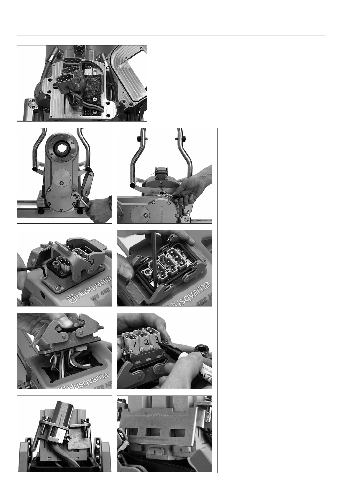
Preparations
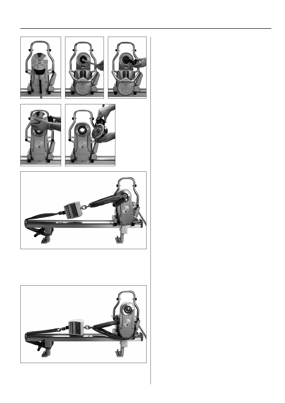
The blade flange hub must be removed for the test.
1. Starting position (blade side).
2. Loosen the screw (motor side).
3. Pull out the stud.
4. Turn the water connection horizontally to the right
(blade side).
5. Lift off the blade flange hub.
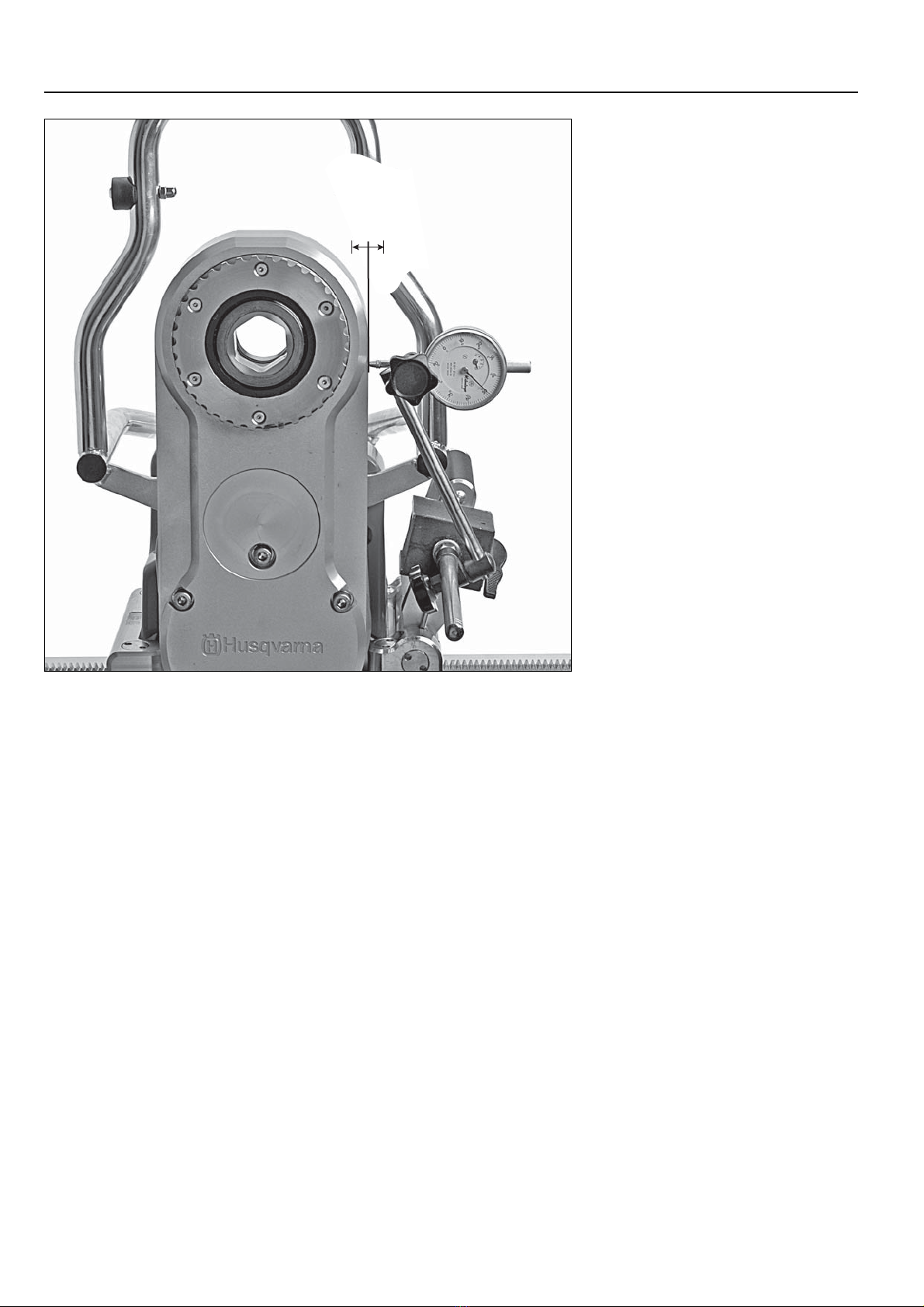
Arm feed
Arrange the scales as shown in the illustration using an
appropriate load belt and a steel shaft that fits through the
arm hole. In order to get the right value for the force of the
pivoting arm, the angle between the pivoting arm and load
belt must be as close to 90° as possible.
The arm must be able to pull at least 290 kg (640 lb) in both
directions. The following cases may occur:
The force is different depending on which way the arm pulls.
– Adjust the position of the HALL sensor card, see Page 23.
It does not achieve 290 kg (640 lb).
– Adjust the position of the HALL sensor card, see Page 23.
– If the motor is working but the arm has stopped, adjust the
slip clutch arm, see Page 39, Paragraph 8.
The saw carriage moves when the force to the arm increases.
– The carriage's slip clutch must be adjusted, see Page 43.
Carriage feed
Arrange the scales as shown in the figure using appropriate
load belts.
The carriage must be able to pull at least 290 kg (640 lb) in
both directions. The following cases may occur:
The force is different depending on which way the carriage
pulls.
– Adjust the position of the HALL sensor card, see Page 23.
It does not achieve 290 kg (640 lb).
– Adjust the position of the HALL sensor card, see Page 23.
– If the feeding motor is running but the carriage is not
moving, adjust the carriage slip clutch, see Page 43.
4 5
3