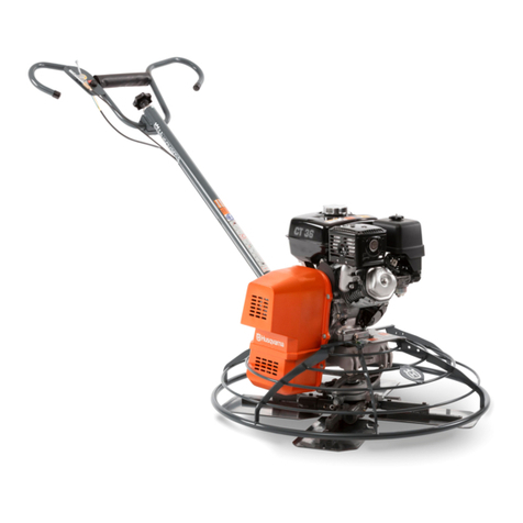
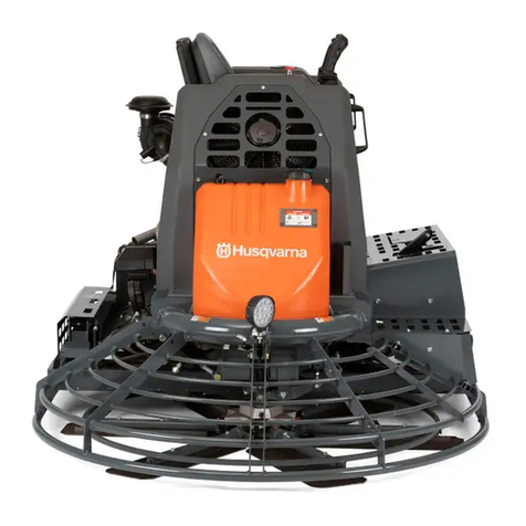
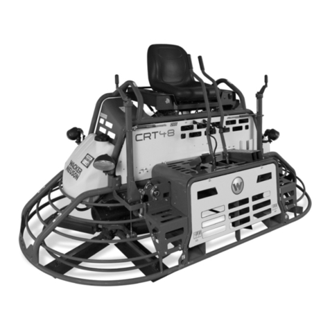
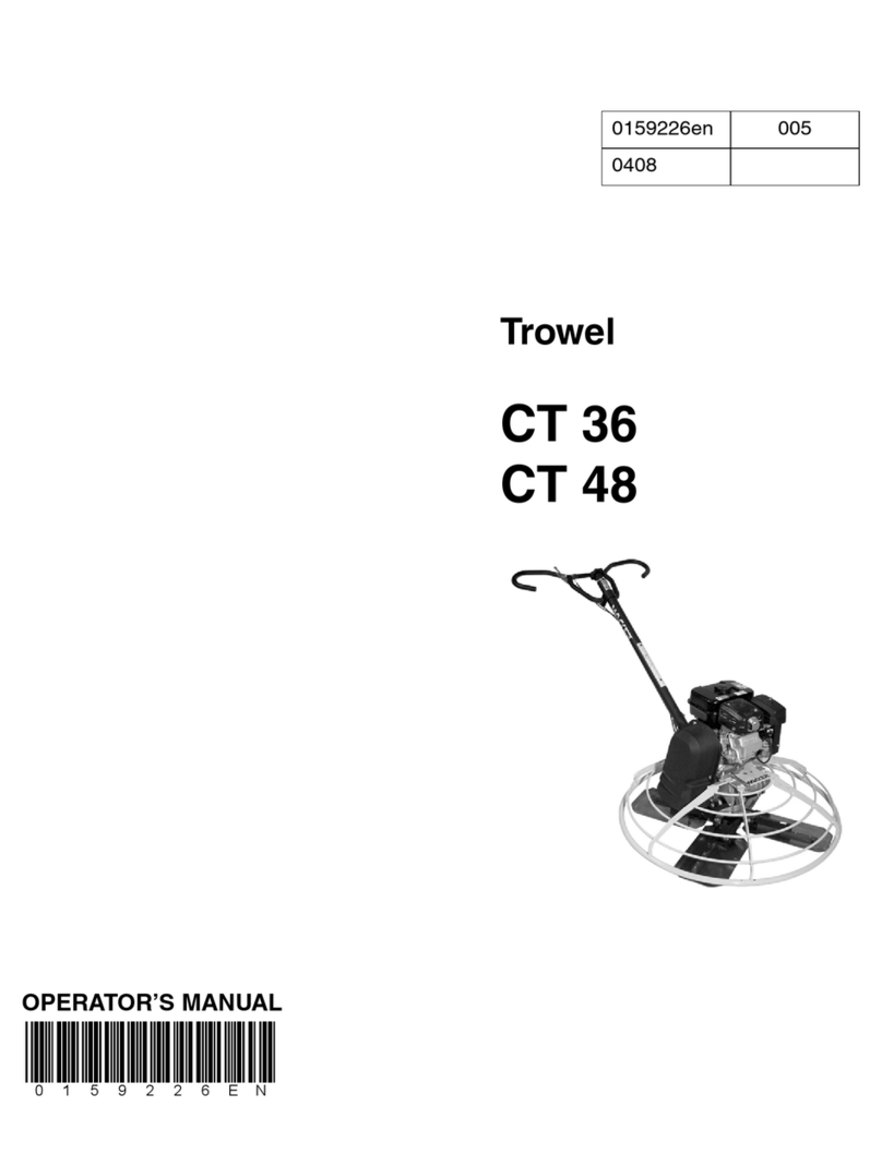
Husqvarna CT 36A/A-V User manual

CT36A/A-V, CT48A/A-V
EN Operator's manual 2-31

Contents
Introduction..................................................................... 2
Safety..............................................................................5
Assembly........................................................................ 9
Operation...................................................................... 11
Maintenance................................................................. 15
Troubleshooting............................................................ 20
Transportation, storage and disposal........................... 22
Technical data.............................................................. 25
Accessories.................................................................. 29
Declaration of Conformity............................................. 30
Introduction
Product description
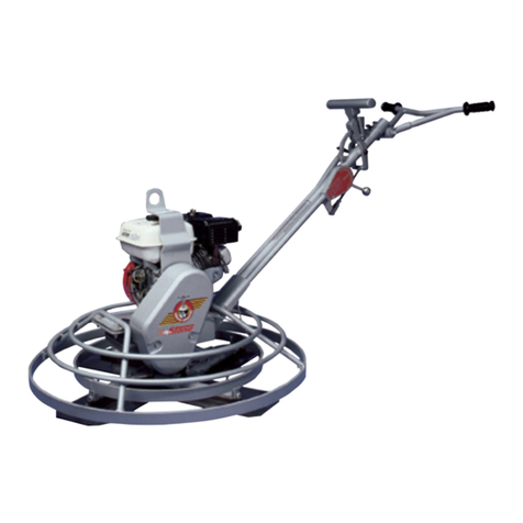
This product is a pedestrian-controlled trowel, which is
a concrete smoothing machine. It uses gasoline as fuel
and has a 4-stroke combustion engine.
The product can be used with the optional accessory
floating disc.
Intended use
The product is for professional operation only. The
product is used for floating and burnishing curing
concrete before the surface is too dry to get the desired
finishing. The product must only be used outdoors or in
areas with sufficient airflow. Do not use the product for
other tasks.
Product overview
17
15 16
23
22
21
20
19
18
24
1
2
3
4
5
10
14
9
6
11
12
8
7
13
21452 - 003 - 30.01.2023

Note: There are 4 different combinations of handle
and blade pitch control: T, ADJ-T, ADJ-P and FOLD-
ADJ-T. Refer to
Technical data on page 25
for
information about handle and blade pitch control on your
product.
1. Throttle control
2. Stop button for the engine
3. Blade pitch knob (T models)
4. Handle
5. Lever for handle height adjustment (ADJ models)
6. Pro-Shift® lever for blade pitch adjustment (P
models)
7. Belt cover
8. Locking knob for the handle (FOLD models)
9. Handle holder
10. Protection ring
11. Blade
12. Type plate (CE)
13. Type plate (North America)
14. Lifting point
15. Engine ON/OFF switch
16. Oil drain hose
17. Oil tank cap and dipstick
18. Starter rope handle
19. Air filter cover
20. Spark plug
21. Muffler
22. Fuel tank
23. Fuel tank cap
24. Operator's manual
Symbols on the product
WARNING! This product can be
dangerous and cause serious injury or
death to the operator or others. Be careful
and use the product correctly.
Read the manual carefully and make
sure that you understand the instructions
before you use the product.
Use safety helmet, glasses and ear
protection.
Use safety foot wear.
Use protective gloves.
WARNING! Keep sparks and flames away
from the product. Risk of fire.
Lifting point.
Stop the engine before you fill fuel.
Use clean, filtered fuel.
WARNING! Risk of injury. Be careful
around the drive belt.
WARNING! Hot surface.
WARNING! Keep your hands away from
the blades.
WARNING! Keep your feet away from the
blades.
WARNING! Remove the floating disc
before you lift the product.
WARNING! The exhaust
fumes from the engine
contain carbon monoxide,
an odorless, poisonous
and very dangerous gas.
Do not run the product in-
doors or in closed spaces.
1452 - 003 - 30.01.2023 3

Engine stop button.
This product is in compliance with
applicable EC directives.
This product conforms to the applicable
UK regulations.
Note: Other symbols/decals on the product refer to
special certification requirements for some markets.
Start instruction decal
Refer to
To start the product on page 12
for
instructions.
Type plate (CE)
R
4
5
6
7
1 2 3
1. Product weight
2. Manufacturer
3. Rated power
4. Product type
5. Serial number
6. Product number
7. Production year and week
Type plate (North America)
1 2 3
4 65
1. Product number
2. Production year
3. Production week
4. Model and product type
5. Serial number
6. Manufacturer
Product liability
As referred to in the product liability laws, we are not
liable for damages that our product causes if:
• the product is incorrectly repaired.
• the product is repaired with parts that are not
from the manufacturer or not approved by the
manufacturer.
• the product has an accessory that is not from the
manufacturer or not approved by the manufacturer.
• the product is not repaired at an approved service
center or by an approved authority.
41452 - 003 - 30.01.2023

Safety
Safety instructions for operation
WARNING: Read the warning
instructions that follow before you use the
product.
• Make sure that you know how to stop the engine
quickly in an emergency.
• The operator must have the physical strength that is
necessary to operate the product safely.
• Do not operate the product without all protective
covers installed.
• Use personal protective equipment. Refer to
Personal protective equipment on page 7
.
• Wet concrete can cause chemical burns. Use
protective clothing and remove wet concrete
immediately if you get it on your skin.
• Make sure that only approved persons are in the
work area.
• Keep the work area clean and bright.
• Make sure that you are in a safe and stable position
during operation.
• Make sure that there is no risk that you or the
product can fall from a height.
• Make sure that there is no grease or oil on the
handle.
• Do not use the product in areas where fire or
explosions can occur.
• The product can cause objects to eject at high
speed. Make sure that all persons in the work
area use approved personal protective equipment.
Remove loose objects from the work area.
• Before you go away from the product, stop the
engine and make sure that there is no risk of
accidental start.
• Make sure that clothes, long hair and jewelry do not
get caught in moving parts.
• Keep your hands and feet away from the blades.
• Do not sit on the product.
• Do not hit the product.
• Always operate the product from behind with your
hands on the handle.
• Do not operate the product near electrical cables.
The product does not have electrical insulation and
injury or death can occur.
• Before you operate the product, find out if there are
hidden wires, cables and pipes in the work area.
If the product hits a hidden object, stop the engine
immediately and examine the product and the object.
Do not start to operate the product again until you
know that it is safe to continue.
Safety definitions
Warnings, cautions and notes are used to point out
specially important parts of the manual.
WARNING: Used if there is a risk of
injury or death for the operator or bystanders
if the instructions in the manual are not
obeyed.
CAUTION: Used if there is a risk of
damage to the product, other materials or
the adjacent area if the instructions in the
manual are not obeyed.
Note: Used to give more information that is necessary
in a given situation.
General safety instructions
WARNING: Read the warning
instructions that follow before you use the
product.
• This product is a dangerous tool if you are not
careful or if you use the product incorrectly. This
product can cause serious injury or death to the
operator or others. Before you use the product,
you must read and understand the contents of this
operator’s manual.
• Save all warnings and instructions.
• Comply with all applicable laws and regulations.
• The operator and the employer of the operator must
know and prevent the risks during operation of the
product.
• Do not let a person operate the product unless they
read and understand the contents of the operator's
manual.
• Do not operate the product unless you receive
training before use. Make sure that all operators
receive training.
• Do not let a child operate the product.
• Only let approved persons operate the product.
• The operator is responsible for accidents that occur
to other persons or their property.
• Do not use the product if you are tired, ill, or under
the influence of alcohol, drugs or medicine.
• Always be careful and use your common sense.
• This product produces an electromagnetic field
during operation. This field can under some
circumstances interfere with active or passive
medical implants. To decrease the risk of serious
injury or death, we recommend persons with medical
1452 - 003 - 30.01.2023 5

implants to speak to their physician and the medical
implant manufacturer before operating this product.
• Keep the product clean. Make sure that you can
clearly read signs and decals.
• Do not use the product if it is damaged.
• Do not make modifications to this product.
• Do not operate the product if it is possible that other
persons have made modifications to the product.
Vibration safety
WARNING: Read the warning
instructions that follow before you use the
product.
• During operation of the product, vibrations go from
the product to the operator. Regular and frequent
operation of the product can cause or increase the
degree of vibration-related injuries to the operator.
Injuries can occur in fingers, hands, wrists, arms,
shoulders, and/or nerves and blood supply or
other body parts. The injuries can be debilitating
and/or permanent, and can increase gradually during
weeks, months or years. Possible injuries include
damage to the blood circulation system, the nervous
system, joints, and other body structures.
• Symptoms can occur during operation of the product
or at other times. If you have symptoms and
continue to operate the product, the symptoms can
increase or become permanent. If these or other
symptoms occur, get medical aid:
• Numbness, loss of feeling, tingling, pricking,
pain, burning, throbbing, stiffness, clumsiness,
loss of strength, changes in skin color or
condition.
• Symptoms can increase in cold temperatures. Use
warm clothing and keep your hands warm and dry
when you operate the product in cold environments.
• Do maintenance on and operate the product as
given in the operator's manual to keep correct
vibration levels.
• Gently guide the product to do the work. Do not
push the product with force. Hold the product at the
handles securely, but make sure that you control
the product and operate it safely. Do not push the
handles into the end stops more than necessary.
• Keep your hands on the handle or handles only.
• Stop the product immediately if strong vibrations
suddenly occur. Do not continue the operation
before the cause of the increased vibrations is
removed.
Dust safety
WARNING: Read the warning
instructions that follow before you use the
product.
• Use of the product for operation on dry surfaces
different from those intended can cause increased
dust in the air. Inhalation of dust can cause serious
injury and permanent health problems. Silica dust is
regulated as harmful by several authorities. These
are examples of such health problems:
• The chronic or potentially fatal lung diseases
chronic bronchitis, silicosis and pulmonary
fibrosis
• Cancer
• Birth defects
• Skin inflammation
• Use correct protective equipment to decrease the
quantity of dust and fumes in the air and to decrease
dust on work equipment, surfaces, clothing and
body parts. Examples of controls are dust collection
systems and water sprays to bind dust. Decrease
dust at the source where possible. Make sure that
the equipment is correctly installed and used and
that regular maintenance is done.
• Make sure that the airflow is sufficient in the work
area.
• If it is possible, point the exhaust of the product
where it cannot cause dust to go into the air.
Exhaust fumes safety
WARNING: Read the warning
instructions that follow before you use the
product.
• The exhaust fumes from the engine contain carbon
monoxide which is an odourless, poisonous and very
dangerous gas. To breathe carbon monoxide can
cause death. Because carbon monoxide is odourless
and cannot be seen, it is not possible to sense it.
An early symptom of carbon monoxide poisoning is
dizziness, but sufficient quantity or concentration of
carbon monoxide may cause loss of consciousness,
especially in an enclosed space or area without
adequate ventilation.
• Exhaust fumes also contain unburned hydrocarbons
including benzene. Long-term inhalation can cause
health problems.
• Exhaust fumes that you can see or smell also
contain carbon monoxide.
• Do not use a combustion engine product indoors or
in areas that do not have sufficient airflow.
• Do not breathe the exhaust fumes.
• Make sure that the airflow in the work area is
sufficient. This is very important when you operate
the product in trenches or other small work areas
where exhaust fumes can easily collect.
Noise safety
WARNING: Read the warning
instructions that follow before you use the
product.
61452 - 003 - 30.01.2023
• High noise levels and long-term exposure to noise
can cause noise-induced hearing loss.
• To keep the noise level to a minimum, do
maintenance on and operate the product as
described in the operator's manual.
• Examine the muffler for damage. Make sure that the
muffler is correctly attached to the product.
• Use approved hearing protection while you operate
the product.
• Listen for warning signals and voices when you use
hearing protection. Remove the hearing protection
when the product is stopped, unless hearing
protection is necessary for the noise level in the work
area.
Personal protective equipment
WARNING: Read the warning
instructions that follow before you use the
product.
• Always use approved personal protective equipment
when you operate the product. Personal protective
equipment cannot fully prevent injury but it may
reduce the potential for or severity of injury if an
accident does occur. Let your dealer help you select
the correct personal protective equipment.
• Regularly do a check of the condition of the personal
protective equipment.
• Use an approved protective helmet.
• Use approved hearing protection.
• Use approved eye protection with side protection.
• Use protective gloves.
• Use boots with steel toe-cap and non-slip sole.
• Use approved work clothing or equivalent close-
fitting clothing that has long sleeves and long legs.
Fire extinguisher
• Keep a fire extinguisher near during operation.
• Use a powder fire extinguisher of "ABE" class or a
carbon dioxide fire extinguisher of "BE" type.
Safety devices on the product
WARNING: Read the warning
instructions that follow before you use the
product.
• Do not use the product if the safety devices are not
in proper working order.
• Do a check of the safety devices daily. If your
safety devices are not in proper working order or are
damaged, speak to your Husqvarna service agent.
• Do not make modifications on safety devices
General safety devices
• Examine the protection ring, belt cover, lifting point
and handle regularly to make sure that they are
attached correctly and not damaged.
Engine ON/OFF switch
The engine can only start when the engine ON/OFF
switch is set to "ON". The engine stops when you set the
engine ON/OFF switch to "OFF".
To do a check of the engine ON/OFF switch
1. Start the engine. Refer to
To start the product on
page 12
.
2. Set the engine ON/OFF switch to "OFF". The engine
stops.
Stop button
The product has a stop button for the engine on the right
side of the handle, adjacent to the throttle control. Refer
to
Product overview on page 2
.
To do a check of the stop button
1. Start the engine.
2. Push the stop button and make sure that the engine
stops.
Muffler
The muffler reduces the noise levels and directs exhaust
fumes away from the operator.
Do not use the product if the muffler is missing or
damaged. A damaged or missing muffler may increase
the noise level and the risk of fire.
WARNING: The muffler becomes very
hot during and after use and when the
engine operates at idle speed. To avoid
burn injuries, do not touch the hot muffler.
Be careful near flammable materials and/or
fumes to prevent fire. Use protective gloves
to prevent burn injuries.
To do a check of the muffler
• Examine the muffler regularly to make sure that it is
attached correctly and not damaged.
Blade brake system
The blade brake engages in these situations:
• The input shaft of the gearbox does not rotate.
• There is no resistance against the blades.
The blade brake releases when the input shaft of the
gearbox rotates while there is resistance against the
blades.
1452 - 003 - 30.01.2023 7
To do a check of the blade brake system
1. Stop the engine. Refer to
To stop the product on
page 15
.
2. Move the handle to the left. It the blade brake
system operates correctly there is no resistance and
the blades do not move.
3. Move the handle to the right. It the blade brake
system operates correctly the blades engage the
movement and there is resistance.
Gyroscopic safety switch
The gyroscopic safety switch prevents unwanted
movement of the product and prevents injury from the
handle if the product starts to turn. The gyroscopic
safety switch stops the engine if the operator releases
the handle. The blade brakes engage and the handle
stops before it can turn more than 270°.
To do a check of the gyroscopic safety switch
1. Start the engine and let it operate at idle speed for
2–3 minutes. Refer to
To start the product on page
12
.
2. Push the handle to the right with force. The engine
stops.
a) If the engine does not stop, push the handle
to the right with force again and again until the
engine stops. If the engine does not stop after
you try 5 times, it is necessary to repair the
gyroscopic safety switch.
b) Stop the engine and speak to an approved
Husqvarna service center. Refer to
To stop the
product on page 15
.
WARNING: Do not operate the
product before the gyroscopic safety
switch is repaired.
Fuel safety
WARNING: Read the warning
instructions that follow before you use the
product.
• Fuel is flammable and the fumes are explosive. Be
careful with fuel to prevent injury, fire and explosion.
• Do not breathe in the fuel fumes. The fuel fumes are
poisonous and can cause injury. Make sure that the
airflow is sufficient.
• Do not remove the fuel tank cap or fill the fuel tank
when the engine is on.
• Make sure that the engine is cool before you refuel.
• Do not fill fuel in an indoor area. Insufficient airflow
can cause injury or death because of asphyxiation or
carbon monoxide poisoning.
• Do not smoke near the fuel or the engine.
• Do not put hot objects near the fuel or the engine.
• Do not fill fuel near sparks or flames.
• Before you refuel, open the fuel tank cap slowly and
release the pressure carefully.
• Fuel on your skin can cause injury. If you get fuel on
your skin, use soap and water to remove the fuel.
• If you spill fuel on your clothing, change clothing
immediately.
• Do not fill the fuel tank fully. Heat causes the fuel to
expand. Keep a space at the top of the fuel tank.
• Tighten the fuel tank cap fully. If the fuel tank cap is
not tightened, there is a risk of fire.
• Before you start the product, move the product to a
minimum of 3 m/10 ft from where you refueled.
• Do not start the product if there is fuel or engine
oil on the product. Remove the unwanted fuel and
engine oil and let the product dry before you start the
engine.
• Examine the engine for leaks regularly. If there are
leaks in the fuel system, do not start the engine until
the leaks are repaired.
• Do not use your fingers to examine the engine for
leaks.
• Keep fuel in approved containers only.
• When the product and fuel is in storage, make sure
that fuel and fuel fumes cannot cause damage.
• Drain the fuel in an approved container outdoors and
away from sparks and flames.
Safety instructions for operation near edges
WARNING: Read the warning
instructions that follow before you use the
product.
• There is a risk that the product falls when you
operate it near an edge. Always keep a minimum
of ⅔ of the product on a surface that is sufficiently
stable to hold the product weight.
• If the product falls, stop the engine before you lift the
product back to a surface that is sufficiently stable.
Refer to
To lift the product with lifting equipment on
page 23
.
Safety instructions for maintenance
WARNING: Read the warning
instructions that follow before you use the
product.
• If the maintenance is not done correctly and
regularly, the risk of injury and damage to the
product increases.
• Use personal protective equipment. Refer to
Personal protective equipment on page 7
.
• Stop the engine and make sure that all parts
of the product are cool before you perform the
maintenance.
• Clean the product to remove fuel, oil or debris before
performing the maintenance.
81452 - 003 - 30.01.2023
• Disconnect the spark plug cap before you do the
maintenance.
• Worn blades can have sharp edges. Use protective
gloves and be careful around the blades.
• The exhaust fumes from the engine are hot and can
contain sparks. Do not operate the product in indoor
areas or near flammable material.
• Do not do modifications to the product. Modifications
that are not approved by the manufacturer can
cause serious injury or death.
• Always use original accessories and approved spare
parts. Accessories and spare parts that are not
approved by the manufacturer, can cause serious
injury or death.
• Replace damaged, worn or broken parts.
• Only do the maintenance as described in this
operator's manual. Let an approved service center
do all other servicing.
• Remove all tools from the product before you start
the engine after maintenance. Loose tools or tools
attached to rotating parts can eject and cause injury.
• After maintenance, do a check of the vibration level
in the product. If it is not correct, speak to an
approved service center.
• Let an approved service center do servicing on the
product regularly.
Assembly
To assemble the handlebar
1. On CT 36-5A EU FOLD-ADJ-T: Lift the handle until it
is straight and tighten the knob (A).
A
2. Attach the wires to the handlebar with cable ties.
To install the handle
1. Pull the blade pitch cable (A) from the bottom end of
the handle and remove the cable nut (B).
A
B
2. Remove the 2 bolts (C) and the 2 nuts (D) from the
handle holder.
C
D
3. Lubricate the blade pitch cable. Refer to
Technical
data on page 25
.
4. Put the blade pitch cable above the pulley and out
through the slot (E).
E
E
1452 - 003 - 30.01.2023 9
CAUTION: Make sure that the
blade pitch cable is in the groove of the
pulley and not on the outer side of the
pulley.
5. Put the handle in the handle holder and install the 2
bolts (C) and the 2 nuts (D). Tighten the nuts to 24
Nm/18 lb-ft.
C
D
6. Loosen the blade pitch cable:
F
G
a) For products with blade pitch knob (F), turn the
blade pitch knob fully counterclockwise.
b) For products with Pro-Shift® lever (G), push the
Pro-Shift® lever fully forward.
7. Put the blade pitch cable through the blade pitch
fork.
8. Attach the cable nut to the blade pitch cable.
9. Adjust the cable nut. The adjustment is correct when
the blade pitch cable is straight when the blades
have no pitch.
To install the throttle cable
1. Move the throttle control to the idle speed position.
2. Put the throttle cable through the clamp on the recoil
cover of the engine.
3. Put the bend of the throttle cable in the hole in the
throttle plate (A).
A
B
Note: The air filter assembly can be removed to
get easier access.
10 1452 - 003 - 30.01.2023
4. Hold the throttle control in the idle speed position
while you put the bracket (B) on top of the throttle
cable.
5. Install the air filter assembly if it was removed.
To connect the wires from the handle to
the engine
1. Connect the wires (A) from the handle to the yellow
wires (B) from the engine.
A
B
2. Connect the green ground wire from the handle to
the green wire from the engine.
a) If the product has a green wire installed on the
engine, discard the green wire supplied with the
handle.
b) If the product does not have a green wire
installed on the engine, remove the nut (C),
install the ground wire and tighten the nut to 24
Nm/18 lb-ft.
C
To do a function check after assembly
1. Start the engine. Refer to
To start the product on
page 12
.
2. Do a check of the idle speed and the clutch. Refer to
Technical data on page 25
for the correct value.
a) Make sure that the blades do not rotate when the
engine is at idle speed.
b) Increase the engine speed and make sure that
the blades start to rotate.
3. Do a check of the gyroscopic safety switch. Refer
to
To do a check of the gyroscopic safety switch on
page 8
.
Operation
Introduction
WARNING: Read and understand the
safety chapter before you use the product.
To do before you operate the product
• Read the operator's manual carefully and make sure
that you understand the instructions.
• Read the engine manual that is supplied by the
engine manufacturer.
• Do a check of the safety devices on the product.
Refer to
Safety devices on the product on page 7
.
• Do the daily maintenance. Refer to
Maintenance
schedule on page 16
.
1452 - 003 - 30.01.2023 11
To adjust the handle height
• Loosen the handle adjustment lever. Move the
handle up or down to an applicable height and
tighten the handle adjustment lever.
To install the floating disc
1. Put the floating disc on a hard flat surface.
2. Put the product on top of the floating disc.
3. Align the center of the blade assembly with the
center of the floating disc.
4. Turn the floating disc until the blades engage in the
brackets on the floating disc.
CAUTION: Make sure that the
floating disc is correctly installed before
you operate the product. An incorrectly
installed floating disc does not give a
smooth result.
To start the product
1. Open the fuel valve.
2. Set the throttle control to idle speed.
3. Set the choke control in the correct position.
a) If the engine is cold, close the choke.
b) If the engine is warm or the ambient temperature
is high, open the choke.
4. Set the engine ON/OFF switch to ON.
5. Pull the starter rope handle slowly until you feel
some resistance. When you feel resistance, pull the
starter rope handle quickly and with force.
12 1452 - 003 - 30.01.2023
Note: Do not twist the starter rope around your
hand.
6. Continue pull the starter rope handle until the engine
starts.
CAUTION: Do not pull the starter
rope to full extension and do not let go
of the starter rope handle. Release the
starter rope slowly. If you do not obey
these instructions it can cause damage
to the engine.
7. Open the choke control gradually until it is fully open.
8. Let the engine operate at idle speed for 2–3 minutes.
9. Hold the product securely at the handle with two
hands. Move the throttle control to increase the
engine speed, but do not release the handle.
To adjust the blade pitch
The blade pitch is adjusted gradually.
• For products with a blade pitch knob (A):
A
a) To increase the blade pitch, turn the blade pitch
knob clockwise.
b) To decrease the blade pitch, turn the blade pitch
knob counterclockwise.
• For products with a Pro-Shift® lever (B):
B
a) To increase the blade pitch, pull the Pro-Shift®
lever up in the direction of the handle.
b) To decrease the blade pitch, push the Pro-Shift®
lever down.
Working techniques
The floating operation removes dents on the concrete
surface. The concrete surface must be sufficiently hard
before the floating operation. The concrete surface is
sufficiently hard when a shoe gives not more than 3 mm/
0.12 in. deep recess on the concrete surface.
When the floating operation is completed, the concrete
surface is prepared for the troweling operation. The
troweling operation increases the density of the concrete
surface and makes it smooth and hard.
CAUTION: Look for loose stones on the
concrete surface during operation. Loose
stones can make marks that are not easy
to remove from the concrete surface.
To do the floating operation
1. Set the throttle control to an applicable speed.
CAUTION: Do not set the speed too
high. Too high speed on wet concrete
can cause damage to the surface. Adjust
the speed during the operation as the
concrete becomes harder.
2. Adjust the blade pitch until there is tension in the
blade pitch cable. Refer to
To adjust the blade pitch
on page 13
.
1452 - 003 - 30.01.2023 13
3. Move the product across the concrete surface.
A
B
a) Move from one side to the opposite side across
all of the concrete surface (A). When you turn to
go in the opposite direction, do an overlap of ½
the diameter of the blade assembly.
b) Move from one side to the opposite side across
all of the concrete surface in a perpendicular
pattern (B). When you turn to go in the opposite
direction, do an overlap of ½ the diameter of the
blade assembly.
4. Stop the product and remove it from the concrete
surface.
CAUTION: Do not let the product
stay stationary on the concrete surface.
This can cause marks and damages to
the concrete surface. When the product
stops, immediately lift the product from
the concrete surface.
To do the troweling operation
1. Set the throttle control to an applicable speed.
CAUTION: Do not set the speed too
high. Too high speed on wet concrete
can cause damage to the surface. Adjust
the speed during the operation as the
concrete becomes harder.
2. Adjust the blade pitch until there is tension in the
blade pitch cable. Refer to
To adjust the blade pitch
on page 13
.
3. Move the product across the concrete surface.
A
B
a) Adjust the throttle control to an applicable speed
for the condition of the surface. Too high speed
can cause damage to the surface.
b) Adjust the blade pitch to increase the pressure
on the concrete surface as necessary during
operation.
c) Move from one side to the opposite side across
all of the concrete surface (A). When you turn to
go in the opposite direction, do an overlap of ½
the diameter of the blade assembly.
d) Move from one side to the opposite side across
all of the concrete surface in a perpendicular
pattern (B). When you turn to go in the opposite
direction, do an overlap of ½ the diameter of the
blade assembly.
4. Stop the product and remove it from the concrete
surface.
5. Wait until the concrete is sufficiently set.
6. Do the procedure again and again until the concrete
surface has a satisfactory finish and is fully set.
Note: The period of time between troweling
operations is calculated from how quickly the concrete
sets.
14 1452 - 003 - 30.01.2023

To move the product in different
directions
• To turn to the left, lift the handle.
• To turn to the right, push the handle down.
• To move the product forward, push the handle
forward.
• To move the product rearward, pull the handle
rearward.
To stop the product
1. Move the throttle control to the idle speed position.
2. Push the stop button for the engine. Refer to
Product
overview on page 2
.
3. Set the engine ON/OFF switch to the OFF position.
4. Move the fuel valve to the OFF position.
Maintenance
Introduction
WARNING: Read and understand the
safety chapter before you perform the
maintenance on the product.
WARNING: Before you perform the
maintenance on the product, stop the
product and make sure that all parts of
the product are cool. Refer to
To stop the
product on page 15
.
1452 - 003 - 30.01.2023 15
Put the product on a flat surface.
For all servicing and repair work on the product, special
training is necessary. Professional repairs and servicing
is available. If your dealer is not a service agent, speak
to them for information about the nearest service agent.
For spare parts, speak to your Husqvarna dealer or
service agent.
Maintenance schedule
* = General maintenance done by the operator. The
instructions are not given in this operator's manual.
X = The instructions are given in this operator's manual.
O = Refer to the engine manual for instructions.
Maintenance Before use,
each 10 h
After the
first 20 h
Monthly,
each 200 h
Yearly, each
500 h
Make sure that there are no fuel or oil leaks. *
Clean the product. X
Make sure that nuts and screws are tightened. *
Do a check of the fuel level and the engine oil level. X
Clean the cooling fins of the engine. O O
Make sure that the throttle control and the blade pitch
knob or Pro-Shift® lever can move smoothly. *
Clean the air filter. X X
Lubricate the blade shafts. X X
Lubricate the blade pitch cable and other parts of the
product. *
Replace the engine oil. X X X
Replace the air filter. X
Do a check of the engine speed. O O
Do a check of the oil level in the gearbox. X X
Examine the belt for damage and replace if necessary. X
Examine and clean the spark plug. Replace the spark
plug if it is necessary. O
Clean the fuel valve on the carburetor. O
Clean the spark arrestor screen on the muffler. O
Clean the sediment cup. O
Drain the fuel and clean the fuel tank and the fuel filter. O
Clean and adjust the carburetor. O
To clean the product
CAUTION: Do not use a high-pressure
washer to clean the product.
• Use water and a brush to clean the product.
CAUTION: Do not point the water
directly at the fuel tank cap, electrical
components or the engine.
• Remove concrete from the surfaces of the product
after each operation before the concrete becomes
hard.
• Remove grease and oil from the handle.
16 1452 - 003 - 30.01.2023
To do a check of the engine oil level
1. Remove the oil tank cap and dipstick.
2. Clean the oil from the dipstick.
3. Put the dipstick back fully into the oil tank.
4. Remove the dipstick.
5. Examine the oil level on the dipstick.
6. If the oil level is low, fill with engine oil and do a
check of the oil level again. Refer to
Technical data
on page 25
or the engine manual for the correct
type of oil.
To replace the engine oil
If the engine is cold, start the engine for 1–2 minutes
before you drain the engine oil. This makes the engine
oil warm and easier to drain.
WARNING: Engine oil is very hot
directly after the engine stops. Make sure
the engine is cool before you drain the
engine oil. If you spill engine oil on your skin,
clean with soap and water.
1. Loosen the oil drain hose from the holder.
2. Put a container below the oil drain hose.
3. Remove the plug from the end of the oil drain hose.
4. Tilt the product and let the oil run out into the
container.
5. Install the plug in the oil drain hose.
6. Install the oil drain hose in the holder.
7. Fill with new engine oil. Refer to
Technical data on
page 25
or the engine manual for the correct type
of oil.
8. Do a check of the engine oil level.
Air filter
WARNING: Use approved respiratory
protection when you clean or replace the
air filter. Discard used air filters correctly.
Inhalation of the dust in the air filter may be
dangerous to your health.
CAUTION: Always replace a damaged
air filter, or the dust will go into the engine
and cause engine damage.
To clean or replace the air filter
WARNING: Do not clean the air filter
with compressed air. This causes damage to
the air filter and the risk increases that you
breathe the dangerous dust.
1. Turn the knob on the air filter cover and remove the
air filter cover.
2. Remove the paper filter element and the foam filter
element (A).
A
3. Clean the air filter housing with a brush.
4. Examine the air filter elements for damage.
5. Tap the paper filter element against a hard surface
or use a vacuum cleaner to remove the particles.
CAUTION: Do not let the nozzle of
the vacuum cleaner touch the surface of
the paper filter element. Keep a small
distance. The sensitive surface of the
paper filter element becomes damaged
if objects touch it.
6. Clean the foam filter element with a solution of soap
and water.
7. Flush the foam filter element in clean water.
8. Compress the foam filter element to remove the
water and let the foam filter element dry fully.
9. Lubricate the foam filter element with engine oil.
10. Push a clean cloth against the foam filter element to
remove unwanted oil.
11. Install the air filter in the opposite sequence.
1452 - 003 - 30.01.2023 17
To replace the belt
WARNING: Do not operate the product
without the belt cover installed.
1. Stop the engine and disconnect the spark plug
cable.
2. Remove the screws and washers that hold the belt
cover. Remove the belt cover.
a) A-V models:
b) All other models:
3. Slowly turn the pulley while you remove the belt from
the pulley.
CAUTION: Do not remove the
clutch or the pulley when you replace
the belt. The clutch and the pulley are
aligned at the factory.
4. Install a new belt.
5. Install the belt cover, the washers and the screws.
Torque the screws to 5 Nm/3.7 lb-ft.
To lubricate the blade shafts
• Push grease through the grease nipples until grease
comes out around the blade shafts. Refer to
Technical data on page 25
.
To replace the blades
WARNING: Before you replace the
blades, stop the product, make sure that the
engine is cool and remove the spark plug
cable.
18 1452 - 003 - 30.01.2023

WARNING: Use protective gloves.
1. Remove the screws (A) and remove the blades.
A
2. Apply grease to the threads of the screws to make
the removal of the screws easier the next time.
3. Install the new blades.
a) Make sure that the blades are installed in the
correct position related to how they rotate, as
shown in the illustration.
A
b) Attach the blades with washers and the
lubricated screws (A). Torque the screws to 26
Nm/19 lb-ft.
B
A
4. Put plastic plugs (B) in the remaining holes in the
blades. This is to make sure that the holes are not
filled with concrete during operation.
Gearbox
It is not necessary to do regular maintenance on the
gearbox other than a check of the oil level. If there is
a leakage or other problems with the gearbox, let an
approved service center repair the product.
To do a check of the oil level in the
gearbox
1. Put the product on level ground.
2. Look through the plug at the side of the gearbox.
The oil level is correct if it is at the bottom of the plug
threads.
3. If the oil level is too low, fill with oil to the correct
level. Refer to
Technical data on page 25
for the
recommended oil type.
1452 - 003 - 30.01.2023 19
Troubleshooting
Problem Cause Solution
The product does not
start.
The fuel tank is empty. Fill the fuel tank.
Dirty fuel goes into the engine. Clean the carburetor.
The engine ON/OFF switch is in the
OFF position.
Set the engine ON/OFF switch to the ON position.
The fuel valve is closed. Open the fuel valve.
There is no oil in the engine. Fill engine oil.
The fuel filter or the fuel hose is clog-
ged.
Clean the fuel filter and the fuel hose.
The fuel hose is damaged. Let an approved service center replace the fuel
hose.
The engine ON/OFF switch, the gyro-
scopic switch, the low oil switch or
relay, wires or connectors are dam-
aged.
Let an approved service center repair the product.
The engine is cold. Close the choke.
The engine is damaged. Refer to the engine manual.
The product starts but
the engine speed can-
not be increased.
The throttle cable is damaged. Let an approved service center replace the throttle
cable.
The throttle control and connectors
are loose or incorrectly adjusted.
Let an approved service center repair the throttle
control.
The clutch shoes are worn. Let an approved service center replace the clutch
shoes.
The engine is damaged. Refer to the engine manual.
The product starts at
high speed and the
speed cannot be de-
creased.
The throttle cable is damaged. Let an approved service center replace the throttle
cable.
The throttle control and connectors
are loose or incorrectly adjusted.
Let an approved service center repair the throttle
control.
The engine is damaged. Refer to the engine manual.
The engine does not
stop.
The engine ON/OFF switch, the gyro-
scopic switch, the low oil switch or
relay, wires or connectors are dam-
aged.
Let an approved service center repair the product.
The engine is damaged. Refer to the engine manual.
20 1452 - 003 - 30.01.2023
This manual suits for next models
17
Table of contents
Other Husqvarna Trowel manuals

Husqvarna
Husqvarna CRT 48-35L-PS User manual

Husqvarna
Husqvarna BG 245 User manual

Husqvarna
Husqvarna CT 36A User manual

Husqvarna
Husqvarna Wacker Neuson MCT36-5 CN User manual

Husqvarna
Husqvarna CRT 36-25 User manual

Husqvarna
Husqvarna Wacker Neuson CRT60-74LX User manual

Husqvarna
Husqvarna BG Combi User manual

Husqvarna
Husqvarna BG 245E User manual

Husqvarna
Husqvarna CT 36 Series User manual

Husqvarna
Husqvarna CRT 48-35L User manual