Huvema HU 107 User manual

TO O L PO S TGR I NDE R
HU 107 & HU 055
Tool post grinder

2
CHANGES AND TYPOGRAPHICAL ERRORS
T
able of Contents
1.
General safety requirements
3
2.
Additional safety regulations 4
3.
Technical specifications 4
4.
Features and accessories 5
5.
How to use the tool post grinder 5
5.1
Remove the toolholder 5
5.2
Install the tool post grinder 5
5.3
Adjust centre height 6
5.4
Adjust belt tension 6
5.5
Dressing the grinding stone 6
5.6
Exchange spindle for internal grinding 7
5.7
Insert and assemble internal spindle 7
6.
Electrical connection 8
7.
Extra information 8
8.
Disclaimer 9
9.
Declaration of Conformity 10

3
WIJZIGINGEN
EN
TYPEFOUTEN
VOORBEHOUDEN
T
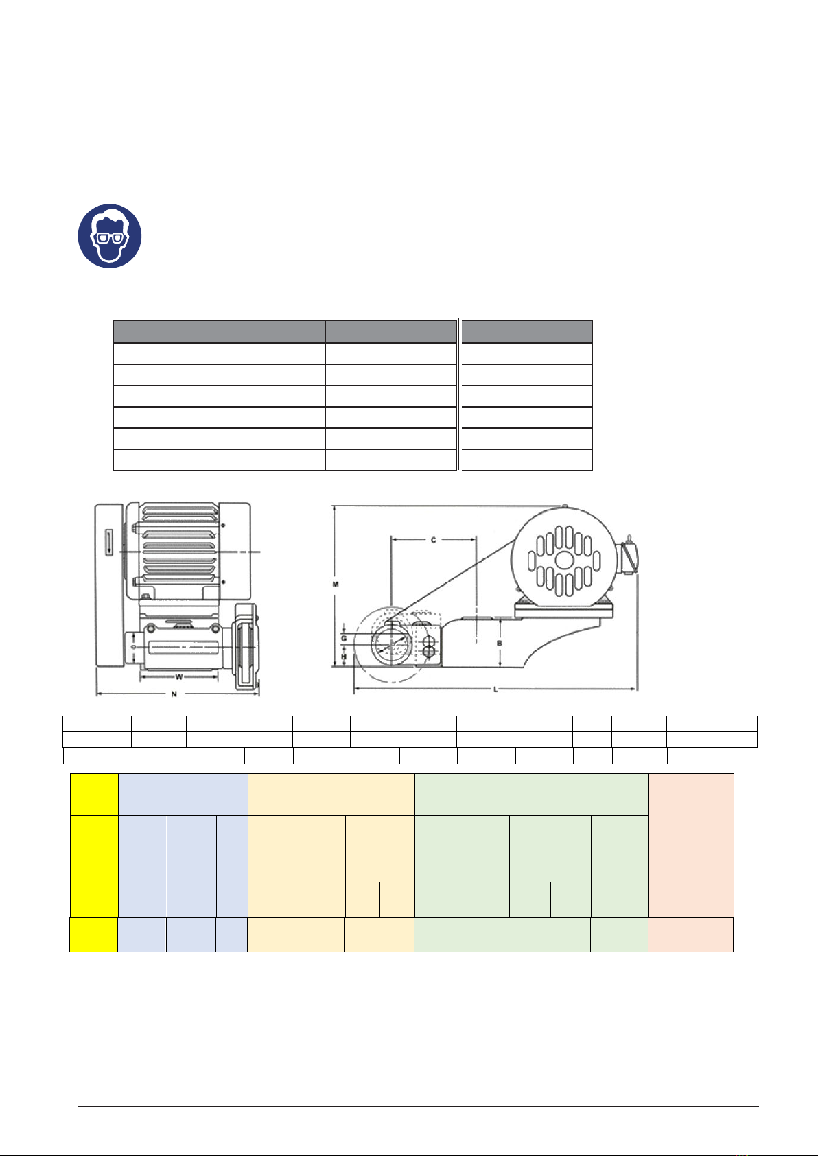
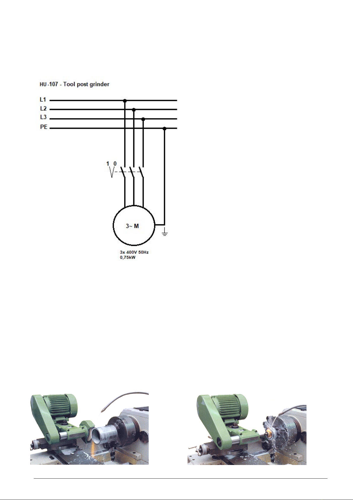
ool post grinder - HU 107 & HU 055
1.
General safety requirements
N.B.: Read the manual carefully toavoid problems.
As with all machines, this machine also involves hazards during the execution ofwork. Proper operation reduces these
risks. Inthe event ofnon-compliance with safety regulations, risks are
unavoidable. Please comply with the general
safety regulations, asapplicable.
The construction of the machine may not be changed in any way. Ifthisnevertheless happens,
this isentirely at
the user's own risk.
1.
Read the manual carefully before working with the machine .
2.
Keep or do not remove protections etc. in place .
3.
Electrically powered machines equipped with a plug should always
be connected to a grounded socket.
4.
Loose levers or actuators should always be removed. Make it a habit to always check the machine before
use.
5.
Keep the workplace clean. A cluttered workplace increases risk.
6.
The machinery must not be set up in a hazardous environment, i.e. not in damp or wet
rooms.
Also, do
not expose the machine to rain. Provide good lighting in the workplace.
7.
Keep children and unauthorized persons away from the machine. They must always be kept at a safe
distance from the
machinery.
8.
Make sure that the workshop cannot be entered by unauthorized persons. Install safety locks in the form
of sliding locks, lockable main switches, etc.
9.
The machine should never be overloaded. The capacity of the machine is greatest when it
is loaded in
the right way.
10.
Use the machine only for the work for which it was made.
11.
Wear the right work clothes. Do not wear loose clothes, gloves, nickers, rings, necklaces,
bracelets or jewellery. These can grip in rotating parts. Wear footwear with rubber soles. Wear
a hairnet in case of long hair.
12.
Always wear safety glasses and proceed according to the safety regulations. For dusty
work, a
dust mask is advisable.
13.
Always fasten workpieces well by means of a machine clamp or a tensioning device. This keeps both hands
free for the operation of the machine.
14.
Keep your balance at all times .
15.
Always keep the machine in optimal condition. To do this, keep the cutting surfaces sharp and clean.
Read the
manual carefully and follow the instructions for cleaning, lubricating and changing
tools.
16.
Before commissioning, it must be ensured that the oil reservoirs are sufficiently filled !
17.
Unplug the power cord from the power outlet before performing maintenance work or replacement of
parts on
the machine.
18.
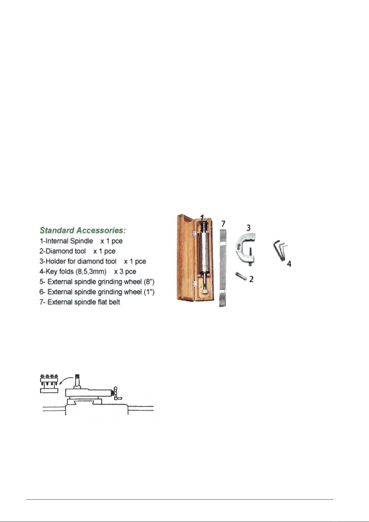
Only use the prescribed accessories. See manual. The use of improper accessories may entail certain risks.
1.
Make sure that the machine cannot start suddenly. Always check that the on/off switch is set to
OFF.
19.
Never stand on the machine or tool. The machine may fall over or come into contact with the
cutting tool.
20.
Check for damaged parts. If there are damaged parts, you must replace or repair them
immediately.
21.
Never leave the machine unattended while it is running. Always switch off the machine, but only after
it has
come to a complete stop.
22.
Alcohol, drugs, drugs. The machine should never be operated when you are under the influence of
these
agents.
23.
Make sure that the machine is voltage-free before carrying out work on the electrical
equipment,
motor, etc.
24.
Keep original packaging due to transport or relocation of the machine.
25.
Machinery must not be used if protective caps or other safety devices have been
removed. If protective
caps are removed during transport (e.g. during repair), you must
reattach them correctly before
(re)commissioning of the machine.

4
CHANGES AND TYPOGRAPHICAL ERRORS
2.
Additional safety requirements
Always remember that:
1.
in the case of maintenance and repair work, the machinery must be "OFF" and stress-free ,
2.
tensioned workpieces may only be measured when the machine is switched off .
Do not hang over the machine, pay attention to loose clothes, ties, shirt sleeves, jewelry
etc. and wear a hairnet. Do not remove protections or protective caps from the machine (never work with an open
protective cap). When working with coarse material,
safety glasses must be used. Blackberries should only be
removed with a hand sweeper, never do this with your hands. Never leave the machine unattended.
Always wear safety glasses!
3.
Technical specification
Model
C
D
H
G
B
W
L
M
N
weight
Packing size
HU-107
100
60
40
10
75
102
485
270
300
38kg
550x400x440
Motor External grinding Internal grinding
Grinder swing
on lathe
Model Power Voltage Pole Size of wheel
diaxwidthxbore
(mm)
(RPM) No
non-
load speed
60hz 50hz
Size of wheel
diaxwidthxbore
(mm)
(RPM) No
non- load
speed
60hz 50hz
Grinding
depth
standard
HU-107 0,75kW 400V 2P 180x19x31,75 3300 2750 38x20x8 18000
12000
16800
11600
110mm 457-762mm
Model
HU-107
Speed RPM
2750
rev/min
Grinding stone
180 x 19 x 31,75mm
Dimensions l x w x h
485 x 300 x 270 mm
Power
0,75 kW
Weight
38
kg
Voltage
3x 400
V
HU-055
3750
rev/min
125 x 19 x 41,27 mm
442 x 286 x 210mm
0,37 kW
26
kg
3x 400
V
HU-055 90 50 40 1075 102 440 240 290 26kg 500x380x340
HU-055 0,37kW 400V 2P 125x19x41,27 4500 3750 25x16x623000
16500
19000
13700
90mm 330-508mm

5
WIJZIGINGEN
EN
TYPEFOUTEN
VOORBEHOUDEN
4.
Features and accessories
Features:
•Both main shafts have been specially deisinged and the precision bearing is used to fit the main shafts
which are made of alloy steel heat -thrated for high wear resistance, precision, as well as
maintaining to the lowest temperature for durability and stability.
•The motor base and the spindle bushing are adjustable.
•The motor is well designed with a special and nice appearance. The RPM of this motor varies
depending on the size of the work piece.
•This grinder is capable of grinding a work piece to a minimum of 3mm in outer diameter and from
2mm up in inner diameter (bore) with a accuracy within 0.003mm and a well finished surface.
(supplied with special attachements)
•The spindel bushing is made of cast iron and supported by three surfaces. Therefore, it si durable and
elastic.
•Materials such as steel, iron, copper (brass), aluminum, cast iron, plastics, porcelain, marble,
regardless of being heat threated, can be grinded with this tool post grinder which functions lie a
cylindrical grinder. Therefore it lowers the cost of production.
•We assure you of high quality products.
5.
H
ow to use the tool post grinder
5.1
R
emove the toolholder
Remove the toolholder from the tool slide
fig. 1
5.2
I
nstall the tool post grinder
Install the tool slide onto the tool slide parallel with the bed ways. Be sure to align the tool post grinder
with the bed ways of the lathe using a micro gauge.

6
CHANGES AND TYPOGRAPHICAL ERRORS
fig. 2
5.3
A
djust the centre height
Adjust the centre height equal to the centre of the lathe.
Then loosen bolt (B) half a turn with a
hexagon wrench. Then use a Allen key at dial (A) and turn it clockwise or anti clockwise to adjust the
height to line-up both centres (0.125 mm for each mark of dial A), then tighten bolt (B) to fasten the
tool post grinders position.
fig. 3
5.4
A
djust belt tension
Adjust the V-belt tension each time the tool grinder is installed to ensure a safe and accurate use of
the tool post grinder. To do so, loosen both bolts (C) a bit, then use handwheel (B) to adjust the V-
belt tension. A correct tension is, that you can either push the V-belt for roughly 10mm in the middle
of the two pulleys.
fig.4
5.5
D
ressing the grinding stone
To dress a grinding stone, use a diamond dressing tool that can be clamped into the chuck (position E)
of the lathe. Then move the tool post grinders stone close to the diamond tool and switch on the tool
post grinder. Then move the stone towards the diamond tool until it touches the stone. Move the tool
post grinder longitudinal along the diamond dressing tool a few time. Then move the tool post grinder
inwards but no more than 0.03mm and repeat the longitudinal movement. Repeat these action until
the diamond dressing tool touches the whole surface of the stone.
fig. 5

7
WIJZIGINGEN
EN
TYPEFOUTEN
VOORBEHOUDEN
5.6
E
xchange spindle for internal grinding (optional)
When internal grinding desired the grinding spindle must be exchanged for a internal grinding spindle.
To do this follow the steps as indicated below.
1. Unscrew the grinding cover (1)
2. Disassemble the V-belt and pulley (2)
3. Remove and disassemble the grinding wheel or sanding belt (3)
4. Disassemble the spindle screw (F), and pull the spindle toward the “IN” sign on the tool post grinder.
The tighten screw (F) again.
fig. 6
5.7
I
nsert and assemble internal spindle
Insert the internal grinding spindle into the spindle taper, change the belt and belt pulley for internal
grinding, adjust the belt pulley for internal grinding, adjust the belt to proper tightness, and tighten
screw (F) for internal grinding.
fig. 7
Make sure that the machine is disconnected from the mains voltage, before service or
starting maintenance.
Always uphold a good position behind the machine and wear suitable PPE’s (Personal Protective Equipment)

8
CHANGES AND TYPOGRAPHICAL ERRORS
6.
E
lectrical connection
The tool post grinder is supplied with a connection cable and on/off switch at the motor. Meaning the tool
post grinder can operate as a standalone apparatus. However, it is recommend the tool post grinder
connected to the lathe controls in order to have an interface in terms of safety.
Fig. 7
Always let a qualified and certified person connected the tool post to your lathe in order to avoid issues or
damaging of the tool post grinder and lathe, but most of all personal injuries.
7.
E
xtra Information
Bear in mind that this tool post grinder is an accessory for lathes and depending on how it is
connected to a power source, it has its risks regarding stopping. As mentioned earlier, it is our
recommendation to have the tool post grinder connected with a good interface with your lathe.
Using the tool post grinder, always be aware to follow the correct working method. Meaning, never
to touch workpiece and grinding stone with each other when either one isn’t rotating. Always,
grind in little steps, never use rapid traverse when both workpiece and grinder are close to each
other. Follow the correct procedures according chapter (5) and never misuse or alter the tool post
grinder other than what it is intended for.
External grinding Internal grinding

9
WIJZIGINGEN
EN
TYPEFOUTEN
VOORBEHOUDEN
Our products are constantly being developed and improved and it is possible that the latest
changes have not yet
been included in this manual. Always mention the year of construction, type and
serial number of your machine in
correspondence.
Neither the manufacturer nor the importer can be held responsible for defects caused
by not carefully reading this
manual or by incorrect use of the machine. No
rights can be derived from this manual.
All rights reserved. Nothing from this publication may be reproduced and/or made public by means of print,
photocopy, microfilm or in any other way whatsoever without the prior written
permission of the publisher.
© Huberts bv, Kennedylaan 14, Veghel, The Netherlands.
Internet:
www.huvema.nl

10
CHANGES AND TYPOGRAPHICAL ERRORS
CE DECLARATION OF CONFORMITY
(in accordance with supplement II A of the Machinery Directive)
Huvema bv, Kennedylaan 14, 5466 AA Veghel, the Netherlands,
Declares that the product described below, towhich this declaration ofconformity refers to, isin
conformity with the essential requirements ofthe following legislation:
Machine: Tool postgrinder
Type: HU 107-4 & HU 055-4
Serial number:
As described in the:
•
Machine Directive 2006/42/EG
•
Electromagnetic Compatibility Directive 2014/30/EU
•
Safety requirements Low Voltage Directive 2014/35/EU
Through the technical standards/specifications specified below:
NEN-EN-ISO 12100:2010, NEN-EN-IEC 60204-1:2018, NEN-EN-IEC 61000-6-4:2019,
NEN-EN-IEC 61000-6-2:2019, NEN-EN-ISO 16089:2016
Veghel, the Netherlands,
Date: January 2022
R. Verberkt,
Managing director

2022
V1
This manual suits for next models
1
Table of contents
Other Huvema Grinder manuals
Popular Grinder manuals by other brands

Jet
Jet IBG-8VS operating instructions

Milwaukee
Milwaukee angle grinder Operator's manual

Parkside
Parkside PDFW 120 A2 Translation of the original instructions

VONROC
VONROC AG501DC Original instructions

Bosch
Bosch GBG 60-20 Professional Original instructions

GÜDE
GÜDE HSS12-131-04B Translation of the original instructions