Hvac Klimaoprema FDC25 User manual

Klimaoprema d.d.
Gradna 78A, 10430 Samobor, Croatia
T. + 385 1 3362513 F. + 385 1 3362905
TECHNICAL MANUAL
FDC25/FDC40
Circular Fire damper
SUMMARY
1.PRODUCTPRESENTATION.................…………………………………………………………….................................................................2
2. DIMENSIONAL RANGE..….……………………………………………………............................................................................................2
3. DIMENSIONS………..………………………………………………………………………...................................................................................3
4. STORAGE AND HANDLING…………………………………………………………....................................................................................4
5. INSTALLATION AND IMPLEMENTATION …………………………………....................................................................................4
6.CONTROLMECHANISMS.………………………………………………………………...............................................................................13
7. ELECTRICAL CONNECTIONS ………………………………………………………………........................................................................15
8.OTHERMECHANISMS..............…………...…………………………………………………........................................................................17
9. EVOLUTION OR SERVICE KITS ………………………………………………………….........................................................................19
10. MAINTENANCE…………....……………………....………………………………….....................................................................................19
11. DOP……...…..………………………………………………………………………..............................................................................................20

1
2
3
4
5
6
7
1. Galvanized steel casing
2. Fire resistant damper blade
3. Control mechanism
4. Intumescent joint
6. Product marking on the casing
7. Thermal fuse
1. PRODUCT PRESENTATION
the wall.
Casing is made out of galvanized steel sheet, damper blade is made of special insulating material, and damper blade
or with electric actuator mechanism.
2. DIMENSIONAL RANGE
Free area for
Free area for
3. DIMENSIONS
FDC25
380
n
Y
A
C
D
n/2+12
n/2+22
E
C
A
380
220
Y
n
A
C
D
n/2+12
n/2+22
E
D
Lenght of damper blade outside of casing (Y dimension on front side and X dimension on back side)
X=(Dn/2)-270 (mm)
Y=(Dn/2)-110 (mm)
Product A C D E
Belimo
BFL (M) 25 200 90 120
BFN (M) 25 225 100 120
BF (M) 50 250 100 120
Klimaoprema
-R (FD 25 & FDC 25) 55 150 105 150
-R (FD 40 & FDC 40) 55 200 105 200
-EMS/EMP (FD 25/40 & FDC 25/40) 55 200 105 200
FDC25
100 0,74 0,50
125 1,17 0,87
160 1,93 1,55
200 3,05 2,56
250 4,79 4,18
300 6,18 5,74
315 7,64 6,87
FDC40
355 9,73 8,33
400 12,37 10,79
450 15,69 13,91
500 19,39 17,41
630 30,86 28,36
710 39,24 36,42
800 49,86 46,68

4. STORAGE AND HANDLING
stalled.
The actions of wedging and caulking during the sealing of the dampers must not cause deformations that will alter the
good functioning of the damper and in particular the closing of the blade.
5. INSTALLATION AND IMPLEMENTATION
5.1 INSTALLATION:
nical manual
5.2 INSTALLATION AND SEALING:
5.2.1 Concrete wall and reinforced concrete wall installation
Place the damper in an opening of
70 mm or more
screws Fill the space between the damper
and the wall with mortar
5.2.2 Aerated concrete ceiling installation and reinforced concrete ceiling installation
Place the damper in an opening of
70 mm or more
screws Fill the space between the damper
and the slab with mortar

5.2.3 Gypsum blocks wall 70mm
Place the damper in an opening of
70 mm or more
screws
Fill the space between the damper
and the wall with mortar Cover the mortar with GFK
5.2.4 Gypsum blocks wall 100mm
screws
Fill the space between the damper
and the wall with mortar Cover the mortar with GFK
Place the damper in an opening of
70 mm or more
* The Kit is universal for all dimen
Width of the
Mounting kit
100 60061429
125 60061430
160 60061431
200 60061432
250 60061433
315 60061435
355 60061436
400 60061437
450 60061438
500 60061439
560 60061440
630 60061441
710 60061442
800 60061443
* The Kit is universal for all dimen
Width of the
Mounting kit
100 60061429
125 60061430
160 60061431
200 60061432
250 60061433
315 60061435
355 60061436
400 60061437
450 60061438
500 60061439
560 60061440
630 60061441
710 60061442
800 60061443

5.2.5 Flexible wall mounting
GFK plates, 12.5 mm thick, installed on a 48 mm wide steel construction. The interior of the
Realization of the steel
construction Place the damper in an opening of
70 mm or more
screws
Fill the space between the damper
and the wall with mineral wool
Cover the mineral wool with GFK
5.2.6 Flexible wall mounting
48 mm width.
Realization of the steel
construction Place the damper in an opening of
70 mm or more
screws Fill the space between the damper
and the wall with mortar
* The Kit is universal for all dimen
Width of the
Mounting kit
100 60061429
125 60061430
160 60061431
200 60061432
250 60061433
315 60061435
355 60061436
400 60061437
450 60061438
500 60061439
560 60061440
630 60061441
710 60061442
800 60061443
* The Kit is universal for all dimen
Width of the
Mounting kit
100 60061429
125 60061430
160 60061431
200 60061432
250 60061433
315 60061435
355 60061436
400 60061437
450 60061438
500 60061439
560 60061440
630 60061441
710 60061442
800 60061443

5.2.7 Installation remote from exible/rigid wall
Recommended wall opening is
to duct
Fill space between duct and wall
Isover BSF in thickness of 1mm
Repeat the same procedure on the
other side.Place the wool on ven
tilation duct and secure on joint
Place ventilation duct trough wall
screws, and screw them to wall
glue Isover BSK in thickness of
2mm.
tion on place where insulation on
damper ends.
5.2.8 Installation in ceiling (Weichschott)
Recommended ceiling opening
+ 400mm, but openings from Ø +
80…600 mm can also be used
Damper blade must be closed
during installation!
screws
Cut additional 50 mm thick rings to
both sides
Connections of mineral wool
should be sealed with intumescent
and damper casing must be coated
coating

MANUAL FUSE ONLY MECHANISM (Non-evolutive)
6. CONTROL MECANISMS
Options :
electric limit switch indicating CLOSED position
electric limit switch indicating OPEN position
MANUAL FUSE ONLY MECHANISM UPGRADABLE TO SOLENOID ACTUATOR
FD25/FD40 in self-operating version
Activation :
Resetting :
To open the damper, insert the screwdriver into the
counterclockwise
To close the damper, press the thermal fuse head with
a screwdriver
5.2.9 Installation in exible wall (Weichschott)
Recommended wall opening for
400mm, but openings from Ø +
80…600 mm can also be used
Damper blade must be closed
during installation!
Cut additional 50 mm thick rings to
both sides
Connections of mineral wool seal
sealant. Mineral wool and damper
casing must be coated with 2 mm
Space between casing and wall
galvanized steel
Washer, galvanized steel
Nut, galvanized steel
galvanized steel
secured with self tapping screw
to damper housing
Suspension for mortarless installation
er with mineral wool in solid walls,
1
2
3
4
5
1
45
1
3
2
Wall
installation Ceiling installation

To open the damper, insert the screwdriver into the
counterclockwise
To close the damper, press the thermal fuse head with
a screwdriver
Options:
electric limit switch indicating CLOSED position
electric limit switch indicating OPEN position
additional electric limit switch indicating CLOSED position
additional electric limit switch indicating OPEN
FD25/FD40 solenoid actuator version
Activation:
Resetting:
Reminder:
7. ELECTRICAL CONNECTIONS
FD25 MANUAL FUSE ONLY MECHANISM
Electronic control board
MANUAL FUSE ONLY MECHANISM UPGRADABLE TO SOLENOID ACTUATOR

ELECTRICAL SPECIFICATIONS FD25 FUSE ONLY FD25/FD40 FUSE ONLY UPGRADABLE TO SOLENOID
ACTUATOR
Nominal voltage N/A
Power N/A
and FDCB contactors
1mA…500mA,
5VDC…48VDC 1mA…500mA, 5VDC…48VDC
Blade closure time
Blade opening time
Manual
Degree of protection IP 42 IP 42
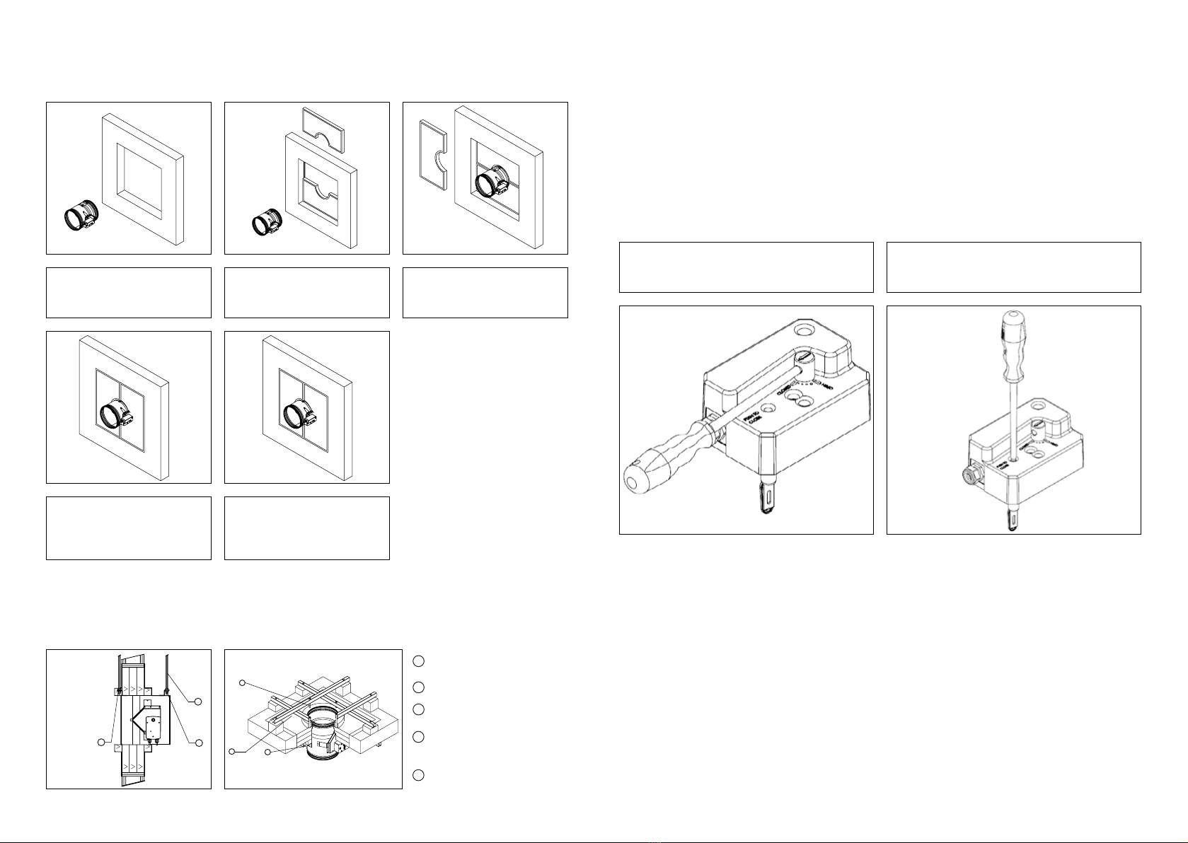
8. OTHER MECHANISMS
Belimo
Operation
Damper is delivered in closed position. When
electric actuator is connected to the power
which is it blocked, the electromotor will stop.
when a power failure occurs. Thermal tripping
the switch on the thermal tripping device will
close damper. When switch on tripping device
is released, the damper will open.
Damper can be opened without connecting
to a voltage with enclosed handle turning in
the direction of the arrow on electric actua
and BFN.
To unlock the electromotor, turn handle clock
release brake for Belimo BFL and BFN. After re
actuator will not move the damper into closed
Type of Belimo actuator BFL24-T BFN24-T BFL230-T BFN230-T BF24-T BF230-T
Nominal
voltage /
power con-
sumption
voltage AC/DC 24V,
50/60Hz AC 24V,
50/60Hz AC 230V,
50/60Hz AC 230V,
50/60Hz AC/DC 24V,
50/60Hz AC 230V,
50/60Hz
opening 2,5 W 4 W 3,5 W 5 W 7 W 8.5 W
holding 0,8 W 1,4 W 1,1 W 2,1 W 2 W 3 W
for wire sizing 4 VA 6 VA 6,5 VA 10 VA 10 VA 11 VA
End switch 1 mA...3 A
(0,5 A), DC 5
V...AC 250V
1 mA...3 A
(0.5 A), DC 5
V...AC 250 V
1 mA...3 A
(0.5 A), DC 5
V...AC 250 V
1 mA...3 A
(0.5 A), DC 5
V...AC 250 V
1 mA...6 A (3
A), DC 5 V...
AC 250 V
1 mA...3 A
(0.5 A), DC 5
V...AC 250 V
Running
time
motor <60 s <60 s <60 s <60 s <120 s <120 s
spring-return ~20 s ~20 s ~20 s ~20 s ~16 s ~16 s
Ambient temperature range min. -30°C, max. 50°C
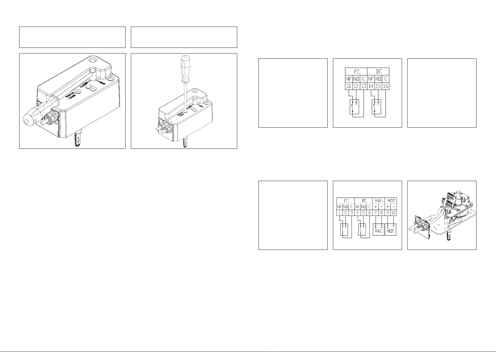
Wiring diagram

1
2
S1 common micro switch closed damper
S2
S3
S4 common micro switch open damper
S5
S6
Tf1
Tf2
Tf3
SCHISCHEK ExMax
Operation
Damper is delivered in closed position. When electric
will open. When the damper reaches the end position
device will close damper. When switch on tripping de
vice is released, the damper will open.
Damper can be opened without connecting to a voltage with enclosed
EXA 14 ATEX0064X
94/9/EC.
Wiring diagram
10. MAINTENANCE
9. EVOLUTION OR SERVICE KITS
Designation Code
Fuse only mechanism
Fuse kit FD-JHERM-72
Double contact S kit FD-S-KIT
Upgradeable to solenoid
4-contacts S2 kit FD-DS-KIT
Solenoid current emission kit FD-EMS-KIT
Solenoid current break kit FD-EMP-KIT

11. DOP
1. Unique identification code of the product-type: Rectangular fire damper
2. Identification of the construction product: FD25/40
3. Intended use(s) of the construction product: Rectangular fire damper to be used in conjunction with fire separating elements to maintain fire compartments in HVAC installations.
4. Name and contact address of the manufacturer: Klimaoprema d.d., Gradna 78A, 10430 Samobor
5. Not applicable
6. System of assessment and verification of constancy of System 1
performance of the construction proudct
7. In case of the declaration of performance concerning a The notified body 1396 carried out the initial inspection of the manufacturing plant and of the factory
construction product covered by a harmonised standard: production control as well as the continous surveillance, assessment and evaluation of factory production
control under system 1 and issued the Certificate of constancy of performance 1812 - CPR - 1162
8. Not applicable
9. Declared performance according to EN 15650: (Fire resistance according to EN 1366-2 and classifications according to EN 13501-3)
Essential characteristics Performance
Range Supporting construction Supporting construction details Type of installation Classification
EI 120 (ve i↔o)S (500Pa)
Reinforced concrete (≥2200kg/m3) ≥100mm/battery EI 120 (ve i↔o)S (500Pa)
Gypsum blocks (≥995kg/m3) ≥70mm EI 120 (ve i↔o)S (500Pa)
EI 120 (ho i↔o)S (500Pa)
Reinforced concrete (≥2200kg/m3) ≥100mm EI 120 (ho i↔o)S (500Pa)
Nominal activation conditions/sensitivity according to ISO 10294-4:
Passed
- sensing element load bearing capacity
- sensing element response temperature
Response delay (closing time) according to EN 1366-2: Passed
Operational reliability (opening, closing) according to EN 1366-2: Passed
Durability of response delay according to ISO 10294-4: Passed
- sensing element response to temperature and load bearing capacity
Durability of operational reliability (opening and closing cycle) according to EN 15650:Passed
- Belimo, Schischek, Siemens - 10 000 cycles
- Fuse only, Fuse + electromagnet (Klimaoprema) - 300 cycles
Protection against corrosion according to EN 60068-2-52:NPD
Damper blade and casing leakage according to EN 1751:Class ≥C
10. The performance of the product identified in points 1 and 2 is in conformity with the declared performance in point 7.
This declaration of performanse is issued under the sole responsibilty of the manufacturer identified in point 4.
Signed for on behalf of the manufacturer by:
Sergio Galošić, General manager
Samobor, 3. February 2017
DECLARATION OF PERFORMANCE
No: DoP 710/207_1_EN
Harmonised standard EN 15650:2010
Type of installation: built in, 0-90-180-270⁰
Flexible wall
Plasterboard type 98/48 ≥100mm
Gypsum plaster/Mortar
EI 120 (ve i↔o)S (500 Pa)
Plasterboard type 98/48 ≥100mm
Mineral wool + cover boards
EI 90 (ve i↔o)S (500 Pa)
Floor/ceiling
Aerated concrete (≥550kg/m3)
≥
100mm
Gypsum plaster/Mortar
Rigid wall
Aerated concrete (≥550kg/m3)
≥
100mm/battery
Gypsum plaster/Mortar
100x200 mm up to
1500x800 mm

NOTES:

Klimaoprema d.d.
Gradna 78A, 10430 Samobor, Croatia
www.klimaoprema.hr
This manual suits for next models
1
Table of contents
Popular Fire And Smoke Damper manuals by other brands

Helios
Helios BTK Series Installation and operating instructions

LUCOMA
LUCOMA DRK Installation, operation and maintenance instructions

Ruskin
Ruskin actionair ES Series Operating and maintenance manual

Swegon
Swegon REACT Pa Instructions for use

mercor
mercor mcr WIP PRO Series Technical manual

Greenheck
Greenheck GFSD Series Installation, operation and maintenance manual