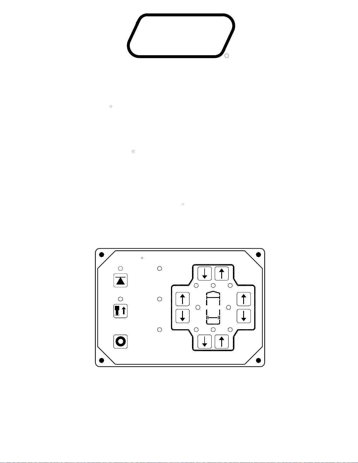
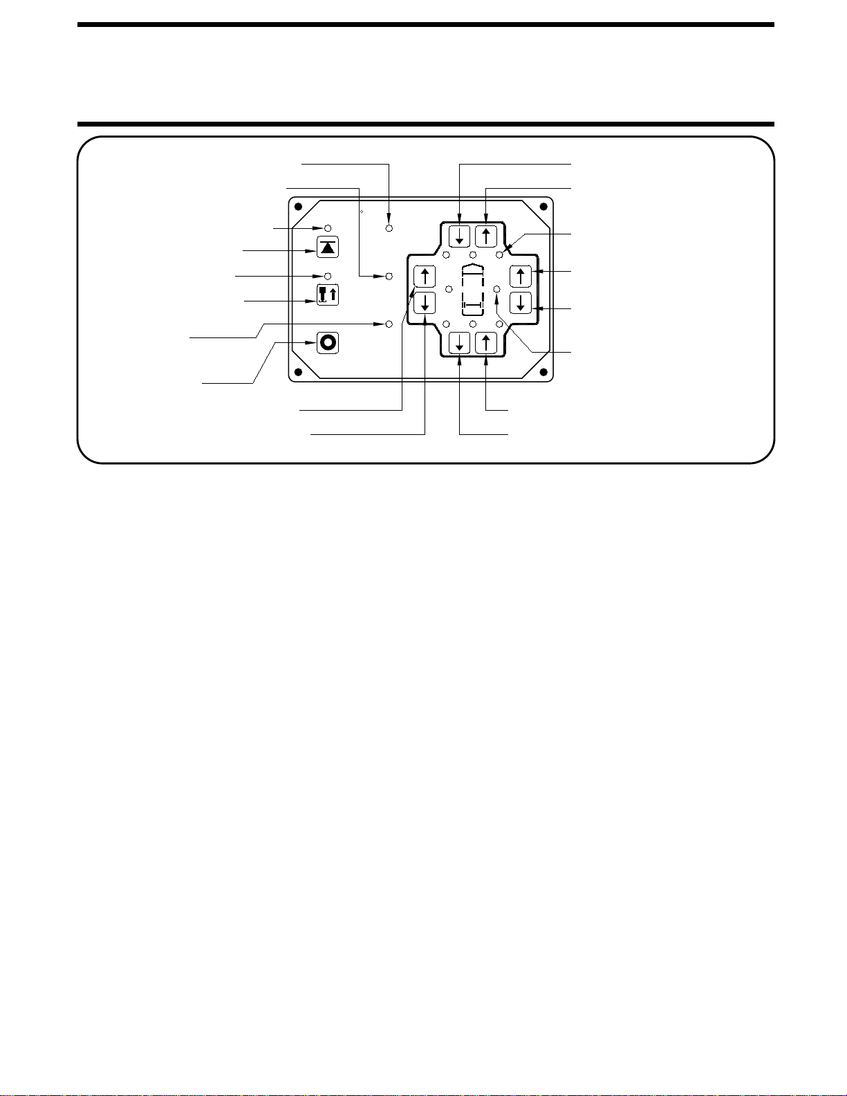
OPERATING PROCEDURES
MP34.431
06MAY1
ROOM EXTEND PROCEDURE
CAUTION:
1. Unlock all room-locking devices.
the room remove it before extending the room.
CAUTION:
extend the room.
3. To extend the room, press and hold the
ROOM CONTROL SWITCH in the "EXTEND" position
the operation of the room.
ROOM RETRACT PROCEDURE
2. To retract the room press and hold the
ROOM CONTROL SWITCH in the "RETRACT" position
the operation of the room.
4. Engage all room-locking devices.
IMPORTANT: Room-locking devices should be locked
while traveling.
OPERATING THE ROOM WITH ANY
KEEP PEOPLE AND OBSTRUCTIONS
CLEAR OF ROOM WHEN OPERATING.
CAUTION:
CLEAR OF ROOM WHEN OPERATING.
KEEP PEOPLE AND OBSTRUCTIONS
5. If the room will not retract see the MANUAL ROOM
RETRACT PROCEDURE.
NOTE: The park brake must be set before a room can be
NOTE:
NOTE: If the MANUAL RETRACT WINCH is attached to
NOTE: Make sure there is adequate clearance to fully
NOTE: Releasing the ROOM CONTROL SWITCH will hal
NOTE: Releasing the ROOM CONTROL SWITCH will hal
NOTE: The park brake must be set before a room can be
extended or retracted.
extended or retracted.
ROOM-LOCKING DEVICES LOCKED OR THE MANUAL-
RETRACT WINCH ATTACHED CAN CAUSE PERSONAL
INJURY AND VEHICLE DAMAGE. IT IS THE OPERATOR’S
RESPONSIBILITY TO ENSURE THAT ALL ROOM-LOCKING
DEVICES AND THE MANUAL RETRACT WINCH ARE
DISENGAGED BEFORE OPERATING THE ROOM.
after the room is fully extended or stops moving.
in the "EXTEND" position for more than ten seconds
of the room, do not reverse direction of the room until
after the room is fully extended. This assures proper
Hold the switch to "EXTEND" three or four seconds
pressurization of the cylinders.
Do not hold the ROOM CONTROL SWITCHIMPORTANT:
NOTE:
During normal operation
the room is fully extended. If necessary, the direction
of the room may be reversed, but watch for binding of
the room. If the direction of the room has been
reversed, DO NOT re-extend the room until the room
has been fully retracted.
If either side of the room stops moving, release the
room control switch immediately. DO NOT force the
room. DO NOT reverse direction of the room, contact
HWH Customer Service for assistance 1-800-321-3494.
HWH Customer Service for assistance 1-800-321-3494.
room. DO NOT reverse direction of the room, contact
room control switch immediately. DO NOT force the
If either side of the room stops moving, release the
after the room is fully retracted or stops moving.
in the "RETRACT" position for more than ten seconds
Do not hold the ROOM CONTROL SWITCH
reversed, DO NOT retract the room until the room
the room. If the direction of the room has been
of the room may be reversed, but watch for binding of
the room is fully retracted. If necessary, the direction
of the room, do not reverse direction of the room until
During normal operation
Hold the switch to "RETRACT" three or four seconds
after the room is fully retracted. This assures proper
has been fully extended.
pressurization of the cylinders.
IMPORTANT:
NOTE:
until the room is fully retracted.
until the room is fully extended.
2. Turn the ROOM OPERATOR’S PANEL Key Switch to "ON". 4. Turn the panel Key Switch to "OFF" and remove the Key
to prevent undesired operation of the room.
1. Turn the ROOM OPERATOR’S PANEL Key Switch to "ON".
3. Turn the panel Key Switch to "OFF" and remove the Key
to prevent undesired operation of the room.
Refer to vehicle manufacturer for proper sequence of
room extension and leveling system operation.
Refer to vehicle manufacturer for proper sequence of
room extension and leveling system operation.