HWH 2000 SERIES User manual

H
CORPORATION
H
W
R
SLOPE
EXCESS
NOT IN
PARK/
BRAKE
TRAVEL
CAUTION!
COMPUTERIZED LEVELING
UNDERSTAND OPERATOR’S MANUAL BEFORE USING. BLOCK FRAME AND TIRES
SECURELY BEFORE REMOVING TIRES OR CRAWLING UNDER VEHICLE.
OFF RAISE
STORE DUMP
LEVEL
HYD AIR
HWH CORPORATION
(On I-80, Exit 267 South)
2096 Moscow Road | Moscow, Iowa 52760
Ph: 800/321-3494 (or) 563/724-3396 | Fax: 563/724-3408
www.hwh.com
AP46142
Straight-Acting Jacks
Air Leveling
FEATURING:
BI-AXIS Hydraulic Leveling
Touch Panel Leveling Control
R
HWH COMPUTER - CONTROLLED
2000 SERIES LEVELING SYSTEM
OPERATOR’S MANUAL
R
ML46143/MP04.3948
01MAR10
MODE

WARNING !
READ THE ENTIRE OPERATOR’S MANUAL BEFORE OPERATING.
MOVE FORWARD OR BACKWARD WITHOUT WARNING CAUSING INJURY OR DEATH.
CAUSING INJURY OR DEATH.
CHIPS, OIL LEAKS, ETC. FOLLOW ALL OTHER APPLICABLE SHOP SAFETY PRACTICES.
OPERATOR’S MANUAL
MP14.0010
07APR08
BLOCK FRAME AND TIRES SECURELY BEFORE CRAWLING UNDER VEHICLE. DO NOT USE LEVELING JACKS OR AIR
SUSPENSION TO SUPPORT VEHICLE WHILE UNDER VEHICLE OR CHANGING TIRES. VEHICLE MAY DROP AND/OR
NEVER PLACE HANDS OR OTHER PARTS OF THE BODY NEAR HYDRAULIC LEAKS. OIL MAY PENETRATE SKIN
WEAR SAFETY GLASSES WHEN INSPECTING OR SERVICING THE SYSTEM TO PROTECT EYES FROM DIRT, METAL
IMPORTANT: IF COACH IS EQUIPPED WITH A ROOM EXTENSION, READ ROOM EXTENSION SECTION BEFORE
OPERATING LEVELING SYSTEM.
DO NOT USE THE DUMP OR RAISE BUTTONS IF THE VEHICLE IS MOVING IN EXCESS OF 5 MPH.
KEEP ALL PEOPLE CLEAR OF VEHICLE WHILE LEVELING SYSTEM AND ROOM EXTENSION ARE BEING OPERATED.
HOW TO OBTAIN WARRANTY SERVICE
THIS IS NOT TO BE INTERPRETED AS A STATEMENT OF WARRANTY
HWH CORPORATION strives to maintain the highest level of
customer satisfaction. Therefore, if you discover a defect or
problem, please do the following:
(563) 724-3396 OR (800) 321-3494. Give your name and
coach was purchased, or the date of system installation,
Notify the dealership where you purchased the
vehicle or had the leveling system installed. Dealership
management people are in the best position to resolve
the problem quickly. If the dealer has difficulty solving
the problem, he should immediately contact the Customer
Service Department, at HWH CORPORATION.
If your dealer cannot or will not solve the problem,
notify the Customer Service Department:
HWH CORPORATION 2096 Moscow Rd. Moscow IA. 52760
address, coach manufacturer and model year, date the
SECOND:
FIRST:
authorization of an independent service facility, to be
defective part, either by appointment at the factory or by the
CORPORATION will authorize repair or replacement of the
determine whether or not your claim is valid. If it is, HWH
HWH CORPORATION personnel will contact you to
during business hours (8:00 a.m. till 5:00 p.m. c.s.t.).
description of the problem, and where you can be reached
determined by HWH CORPORATION. All warranty repairs
must be performed by an independent service facility
authorized by HWH CORPORATION, or at the
HWH CORPORATION factory, unless prior written approval
has been obtained from proper HWH CORPORATION
personnel.
DO NOT TRAVEL IF THE VEHICLE IS NOT AT THE PROPER RIDE HEIGHT. CONTACT MANUFACTURER
TECHNICAL SERVICE FOR TRAVELING WHEN NOT AT THE PROPER RIDE HEIGHT.

CONTROL IDENTIFICATION
MP24.3421
01MAR10
"EXCESS SLOPE"
LIGHT "NOT IN PARK" LIGHT
HYDRAULIC OPERATION
LIGHT
"LEVEL HYD" BUTTON
"STORE" BUTTON
"DUMP" BUTTON
"OFF" BUTTON
"TRAVEL MODE"
LIGHT
LOWER FRONT BUTTON
RAISE FRONT BUTTON
WARNING LIGHTS
(4-Red)
RAISE RIGHT SIDE BUTTON
LOWER RIGHT SIDE BUTTON
LEVELING LIGHTS
(4-Yellow)
RAISE REAR BUTTON
LOWER REAR BUTTON
STORE LIGHT
RAISE LEFT SIDE
BUTTON LOWER LEFT SIDE BUTTON
CONTROL FUNCTIONS
CONTROL BUTTONS
SLOPE
EXCESS
NOT IN
PARK/
BRAKE
TRAVEL
CAUTION!
COMPUTERIZED LEVELING
UNDERSTAND OPERATOR’S MANUAL BEFORE USING. BLOCK FRAME AND TIRES
SECURELY BEFORE REMOVING TIRES OR CRAWLING UNDER VEHICLE.
OFF RAISE
STORE DUMP
LEVEL
HYD AIR
"RAISE" BUTTON
RAISE LIGHT
"LEVEL AIR" BUTTON
AIR OPERATION LIGHT DUMP
LIGHT
IMPORTANT:
hydraulic or air operation.
by exhausting air from the suspension system.
by adding air to the suspension system.
LOWER BUTTONS (DOWN ARROWS):
AIR OPERATION LIGHT:
HYDRAULIC OPERATION LIGHT:
STORE LIGHT:
RAISE LIGHT:
DUMP LIGHT:
"OFF" BUTTON:
"LEVEL HYD" BUTTON:
"STORE"BUTTON:
"LEVEL AIR" BUTTON:
"DUMP" BUTTON:
"RAISE" BUTTON:
RAISE BUTTONS (UP ARROW):
Push the "OFF" button to stop the
This button is used to automatically
This button will lower the whole vehicle
This button will raise the whole vehicle
system is active in the HYDRAULIC LEVELING mode. This
is pushed.
is pushed.
This is a system active and
automatic operation button for hydraulic leveling.
automatic operation button for air leveling.
This light will flash indicating the hydraulic
system is in the STORE mode.
READ "DUMP" AND "RAISE" FUNCTIONS
SECTION CAREFULLY.
These are
momentary buttons used for manually operating the air or
hydraulic leveling systems. Sides or ends of the vehicle will
lower while these buttons are pushed in manual Air Leveling.
This light indicates the
This light indicates the system is
This light will flash when the "DUMP" button
This light will flash when the "RAISE" button
These momentary buttons
are used for manually operating the air or hydraulic leveling
systems. Sides or ends of the vehicle will raise while these
buttons are pushed.
This is a system active and
retract the jacks into the STORE/TRAVEL position. It will also
return the system to the travel mode if air leveling was used.
MODE
INDICATOR LIGHTS
The jacks will retract when in manual Hydraulic Leveling.
light will flash during a leveling procedure.
active in the AIR LEVELING mode. This light will flash during
a leveling procedure.
Pushing OFF will not put
the system in the TRAVEL MODE.

CONTROL IDENTIFICATION
MP24.3422
01MAR10
CONTROL FUNCTIONS (CONT’D)
INDICATORS (CONT’D)
on if the leveling system can NOT level the vehicle.
the "AIR" or "HYD" button is being pushed and the park brake
is not set, provided the ignition is in the "ON" position.
inch or more, the respective red WARNING light will be on,
if the HYDRAULIC OPERATION indicator light is on. If the
AIR OPERATION indicator light is on and the ignition is in the
"ON" position all four red warning lights will be on.
indicator lights. A lit LEVEL indicator light indicates a side,
end or corner of the vehicle is low. These lights can be on
only if the AIR or HYDRAULIC indicator lights are on. Only
one or two LEVEL indicator lights can be on at once. When
all LEVEL indicator lights are out the vehicle is level.
ignition is in the "ON" position and a jack is extended 1 inch
or more, or if a suspension air bag has low air pressure.
is in the "ON" position and a jack is extended 1 inch or more,
or if a suspension air bag has low air pressure.
on if the ignition is "ON" and the Master Warning light is off.
"EXCESS SLOPE" INDICATOR LIGHT:
"TRAVEL MODE" INDICATOR LIGHT:
"NOT IN PARK" INDICATOR LIGHT:
WARNING INDICATOR LIGHTS:
LEVEL INDICATOR LIGHTS:
MASTER WARNING LIGHT:
WARNING BUZZER:
This light will be
This light will be
This light will be on if
When a jack is extended 1
There are four yellow LEVEL
This light will be on if the
The buzzer will sound if the ignition
exceeding 5 MPH if the "DUMP" or "RAISE" buttons are
NOTE: The vehicle can be moved at speeds not
HWH LIGHTED RESET SWITCH
before the leveling system can be operated.
If the lighted reset switch is on, the switch must be pushed
"ACC" position, the lighted reset switch and the
indicator lights will come on. If the ignition is in the "ON" or
leveling system will not operate. If the ignition is off, no
in the HWH CAN network, the network will shut down. The
located on the vehicle dash. If there is a failure at any time
The HWH system has a lighted reset switch that is normally
THE VEHICLE CAN RETURN TO RIDE HEIGHT
POSITION AND THE LIGHTED RESET SWITCH IS ON,
IF THE IGNITION IS IN THE "ON"
suspension will return to the travel mode if the ignition key
system. The Leveling System will not operate. The vehicle
is a problem with the central control module of the network
If the lighted reset switch will not go out when pushed, there
is in the "ON" position.
WITHOUT RELEASING THE PARK BRAKE.
CAUTION:MASTER WARNING Light will come on.
MASTER WARNING INDICATORS
If the HWH buzzer and light are on when ready to travel,
possible problems should be checked and corrected
before proceeding.
If the HWH buzzer and light come on briefly while traveling,
possible problems should be checked when convenient,
but it is not necessary to stop traveling when the warning
buzzer and light do not stay on.
If the HWH buzzer and light come on and stay on, the
vehicle should be pulled over as soon as it is safe to do so.
Any problem found should be corrected before continuing.
It is not recommended to stop on a traveled portion of the
road or anywhere that does not have adequate room to
safely inspect the vehicle.
If a problem that could create a driving hazard is not found,
proceed with caution. The problem may be a faulty indicator
or warning switch. If a driving hazard is found, the problem
should be corrected before traveling. When in doubt, contact
the vehicle manufacturer or HWH customer service for
assistance.
being used. The TRAVEL MODE LIGHT will be off.
The HWH Master Warning light and Buzzer are used to
indicate a jack has not been retracted or has extended
slightly due to thermal expansion, the air pressure in any
suspension air bag drops below 20 psi or the system air
pressure drops below 85 psi. When the Master Warning
light and Buzzer are on the Travel Mode Light will be off. A
jack that extends slightly does not create a driving hazard. A
jack that remains extended more than several inches or low
air pressure can create a driving hazard.

MP25.999
5
18MAR2
1
CONTROL IDENTIFICATION
PUMP RUN TIME
SYSTEM VARIATIONS FOR PUMP RUN TIME
Contact HWH corporation to get specific information about the system in this vehicle.
No matter what HWH system is on the vehicle, the pump should not be ran for more than three minutes
(3" motors) or six minutes (3.7" or 4.5" motors) without allowing the pump motor to cool for thirty minutes.
Continuous operation of the pump motor without allowing the motor to cool can damage the pump motor.
Some HWH systems are equipped with a lighted reset switch.
If the processor turns the pump off because the run time has
been exceeded, the light in the reset switch will turn on. The
With some systems, when the processor has turned the pump off because the run time has been exceeded, power
to the HWH system must be turned off and back on before the system will operate. With motorized vehicles, turn the
ignition off and back on. With non-motorized vehicles, turn the master power switch for the HWH system off and back
DO NOT continue without allowing the pump motor to cool for thirty minutes.
When operating some leveling systems manually or operating the room extensions, the pump will turn off and back
on while pushing the control button when the pump run time has been exceeded.
the pump motor to cool for thirty minutes.
Some systems can be turned back on immediately after the processor turns the pump off.
back on or run the pump without allowing the pump motor to cool for thirty minutes.
Some systems with rooms run the rooms separate from the system processor. These systems do not monitor pump
run time when operating the rooms.
pump motor to cool for thirty minutes.
The HWH systems with a computer processor monitor the pump run time and will turn the pump off if the run time exceeds a
specified time. This time can vary with different systems. Due to available electronics or system design, the pump run time
programs will also vary. Leveling systems and room extensions that are not controlled by a system processor have no pump
run time protection.
thirty minutes.
Pump motors used with HWH leveling systems and room extension systems come in 3 different diameters; 3", 3.7" and 4.5".
Contact the vehicle manufacturer or HWH for help with identifying the motor size.
runs for more than three minutes with a 3" motor; or six minutes with a 3.7" or 4.5" motor that the motor is allowed
to cool for thirty minutes before continuing. Continuous operation of the pump motor without allowing the motor
PUMP RUN TIME
It is important that any time the pump
to cool can damage the motor.
DO NOT run the pump more than three or six minutes without allowing the pump motor to cool for
DO NOT run the pump more than three or six minutes without allowing the
DO NOT turn the system
DO NOT continue without allowin
g
on.
system will not operate until the reset switch is pushed.
DO NOT continue without allowing the pump motor to
cool for thirty minutes. LIGHTED RESET SWITCH
For cold weather information see "COLD WEATHER OPERATIONS" below.
COLD WEATHER OPERATIONS
HWH leveling and room extension systems are designed to function in cold weather down to 0 degrees Fahrenheit. Below
freezing (32 degrees Fahrenheit) the jacks or rooms will operate slower than usual.
For operation in temperatures dropping below -20 degrees Fahrenheit, it is necessary that the system is equipped with oil
designed for extreme cold weather application such as a synthetic oil. (Contact HWH for recommendations.)
DO NOT run the pump motor continuously.
Continuous operation of the pump with slow moving jacks or rooms in cold weather, without allowing the pump motor to
cool will cause the pump motor to burn up and damage the pump assembly.
It is important that any time the pump runs for more than three minutes
continuing. Continuous operation of the pump motor without allowing the motor to cool can damage the motor.
with a 3" motor; or six minutes with a 3.7" or 4.5" motor that the motor is allowed to cool for thirty minutes before

OPERATING PROCEDURES
MP34.0223
01MAR10
AIR LEVELING LOCK OUT
Computerized or manual air leveling functions cannot be
used if hydraulic functions have been used and any jacks
are extended.
If any jacks are extended and the "AIR" button is pushed,
the individual red warning light(s) for the jack(s) extended
will flash for 10 seconds. Hydraulic functions will still
operate while the light(s) are flashing.
manual down arrows can be used to retract the jacks.
retracted with the warning lights off. The "STORE" button or
The "AIR" button will not function until all jacks are fully
PREPARATION FOR TRAVEL
GENERAL INSTRUCTIONS
Start the vehicle’s engine and allow air pressure to build to
or the park brake must be released before the vehicle can return
If air leveling was used, the "STORE" button must be pushed
The "TRAVEL" light on the leveling panel must be on.
Check that the generator slide is fully retracted.
Before traveling, the MASTER WARNING light and buzzer
Also check that the vehicle’s suspension is at the proper height
Visually check that the jacks are in the STORE/TRAVEL position.
recommended level for traveling.
for travel.
must be off.
to travel height.
air suspension can return to travel height.
The ignition switch must be "ON" before the vehicle’s
and a leveling system was used.
allow the vehicle to return to travel height if the ignition is on
Pushing the "STORE" button or releasing the park brake will
system will return to travel height.
released. The system will shut off and the vehicle suspension
hydraulic leveling will be stopped anytime the park brake is
is pressed. If the ignition is in the "ON" position, either air or
system will not turn on when either the "AIR" or "HYD" button
set, the "NOT IN PARK/BRAKE" light will come on, and the
If the ignition is in the "ON" position and the park brake is not
Press the "OFF" button at any time to stop the operation of the
placed under the jacks for hydraulic leveling.
If parking on soft ground or asphalt paving, pads should be
NOTE:
system. The vehicle will not return to TRAVEL MODE.
DO NOT MOVE THE VEHICLE WHILECAUTION:
PROPER RIDE HEIGHT AND THE SLIDE-OUT IS FULLY
TO VISUALLY CHECK THAT THE VEHICLE IS AT THE
IT IS THE OPERATOR’S RESPONSIBILITY
VISUALLY CHECK THAT ALL JACKS ARE FULLY
LIGHTS. IT IS THE OPERATOR’S RESPONSIBILITY TO
HAZARD. DO NOT RELY SOLELY UPON WARNING
JACKS AND OR THE VEHICLE AND CREATE A DRIVING
EXTENDED CAN CAUSE SEVERE DAMAGE TO THE
MOVING THE VEHICLE WITH THE LEVELING JACKS
VEHICLE IS EQUIPPED WITH STRAIGHT-ACTING JACKS.
THE GROUND OR IN THE EXTEND POSITION. THIS
THE LEVELING JACKS ARE STILL IN CONTACT WITH
RETRACTED BEFORE MOVING THE VEHICLE.
CAUTION:
WARNING LIGHT OR BUZZER IS ON, OR IF THE ROOM
DO NOT MOVE THE VEHICLE IF A
pressure if the ignition is in the "ON" position.
is extended two inches or more or if an air bag has low air
The MASTER WARNING light and buzzer will be on if a jack
and park brake off if the ignition is in the "ON" position. See
The "DUMP" and "RAISE" buttons will function with the system
Air and hydraulic leveling can not be used simultaneously.
AIR DUMP AND RAISE FUNCTIONS.
EXTENSION IS EXTENDED. (SEE "MASTER WARNING
CAUTION:
INDICATORS")
RETRACTED INTO THE STORE POSITION.

MP34.2715
01MAR10
AUTOMATIC HYDRAULIC LEVELING
CAUTION:
IMPORTANT: DO NOT interrupt power to the leveling
1. Place transmission in the recommended position for
parking vehicle and set parking brake. Turn the coach
engine off. Turn the ignition to the "ACCESSORY" position.
2. Press the "HYD" button to enter the hydraulic operation
mode. The ON light above the "HYD" button will glow steady.
3. At this time, the operator may want to check the jacks
and place pads under the jacks if the ground will not
4. Press the "HYD" button a second time.
The ON light will start to flash.
The system will automatically extend the jacks to level the
vehicle and then extend any remaining jacks for stabilizing.
After the system has finished leveling and stabilizing, and has
completed the air dump cycle, it will automatically shut off.
5. Turn the ignition switch to the "OFF" position.
JACK RETRACTION
THE OPERATOR MUST BE SURE THAT
THERE ARE NO OBJECTS UNDER THE VEHICLE AND THAT
ALL PEOPLE ARE CLEAR OF THE VEHICLE.
system while the "STORE" indicator light is blinking.
DO NOT push the "OFF" button or turn the ignition key.
4. If jacks cannot be retracted by the above procedure see
MANUAL JACK RETRACTION Section.
CAUTION:
DO NOT MOVE THE VEHICLE WHILE THE
LEVELING JACKS ARE STILL IN CONTACT WITH THE GROUND
OR IN THE EXTEND POSITION. THIS VEHICLE IS EQUIPPED
WITH STRAIGHT-ACTING JACKS. MOVING THE VEHICLE
WITH THE LEVELING JACKS EXTENDED CAN CAUSE
SEVERE DAMAGE TO THE JACKS AND OR THE VEHICLE AND
CREATE A DRIVING HAZARD. DO NOT RELY SOLELY UPON
WARNING LIGHTS. IT IS THE OPERATOR’S RESPONSIBILITY TO
CHECK THAT ALL JACKS ARE FULLY RETRACTED INTO
The system must be allowed to completely finish the
3. The vehicle can be moved as soon as the red warning
lights are out, the jacks are in the STORE/TRAVEL position,
the green "TRAVEL MODE" light is on, and the suspension
air bags are inflated to the vehicles proper ride height.
THE STORE/TRAVEL POSITION AND THE VEHICLE IS AT
THE PROPER RIDE HEIGHT.
NOTE: After pushing the "HYD" button a second time,
the system will begin to dump air from the vehicle
1. Start the engine.
OPERATING PROCEDURES
support the vehicle.
leveling process will begin.
suspension. After approximately 25 seconds, the
EXCESS SLOPE SITUATION: In the event the jacks are
unable to level the coach, the "EXCESS SLOPE" light will
come on. Excess slope is two jacks fully extending without
turning the yellow level light out. The system will not stabilize
the vehicle if the "EXCESS SLOPE" light comes on. One or
more jacks may not be extended. The system will shut off
leaving the "EXCESS SLOPE" light on. The "EXCESS
SLOPE" light will remain on if the ignition is in the "ON" or
"ACC" position, until the jacks have been fully retracted
turning the red warning lights out. Push the "STORE" button
to retract the jacks. Move the vehicle to a more level position
or level the vehicle as close as possible according to the
MANUAL HYDRAULIC OPERATION section.
NOTE: When traveling thermal expansion may cause
a jack to extend slightly. When the "STORE" button
has been used to retract the jacks, the system will
automatically retract any jack that extends due to
thermal expansion.
STORE mode.
IMPORTANT: If a red warning light and buzzer come on
while traveling, the jacks should be checked as soon as
a safe parking location is found.
2. Press the "STORE" button. The store indicator light will
flash. Air will be pumped into the vehicle suspension for 10
seconds before the jacks start to retract and the system goes
into the TRAVEL MODE. The two front jacks will retract for
approximately 5 seconds before the rear jacks start to retract.
As each jack retracts, its red WARNING light will go out. The
system will automatically shut down one minute after the four
individual red "WARNING" lights are out. If any one red
"WARNING light does not go out, the system will continue to
store until the ignition is turned off. The panel will remain on
in the STORE mode for ten minutes after the ignition is
NOTE: If the vehicle is parked or stored with the jacks
extended for an extended period of time and the jacks
fail to retract completely, extend the jacks back down
to the ground then retract the jacks again.
turned off. After ten minutes the panel will turn off.

OPERATING PROCEDURES
MP34.3020
01FEB10
IMPORTANT: Do not continue to push an EXTEND
MANUAL HYDRAULIC OPERATION
1. Place transmission in the recommended position for parking
2. Press the "HYD" button. The indicator light will glow steady.
3. Place pads under the jack feet if the ground will not support
the vehicle on the jacks.
5. The vehicle may be leveled using the manual EXTEND
(UP ARROW) buttons on the right half of the panel. If a yellow
LEVEL SENSING light is on, that side or end of the vehicle is
Jacks will extend (or retract) in pairs to raise (or lower) a side
or end of the vehicle. Any jack not used for leveling can be
extended to the ground. This provides additional stability
button for more than ten (10) seconds after that pair of
6. When leveling is completed, push the "OFF" button on the
touch panel and turn the ignition switch to the "OFF" position.
against wind and activity in the vehicle. Jacks used to
the vehicle, and set the parking brake. Turn the ignition to the
"ACCESSORY" position.
jacks are fully extended.4. Push the "DUMP" button. Wait until all of the air is
exhausted from the vehicles suspension system.
when manual operation of the leveling system is used.
IMPORTANT: Push the "STORE" button before traveling
stabilize the vehicle after leveling is complete should lift the
vehicle slightly after touching the ground.
low. It is best to level the vehicle side to side first, if needed,
before front to rear.

OPERATING PROCEDURES
MP34.3302
01MAR10
MANUAL JACK RETRACTION
been opened far enough to allow the jacks to retract.
the T-Handle will turn harder. Make sure the valves have
will turn several turns easily. As the valve starts to open,
Large style with T-Handle valve release:
power unit. The upper most manifold should control
NOTE: Multiple manifolds may be present on the
retract the jacks.
if the STORE feature on the HWH control panel will not
Use the manual valve release for retracting the jacks only
DO NOT CRAWL UNDER THE VEHICLE, KEEP A SAFE
DISTANCE IN FRONT AND REAR OF THE VEHICLE.
THE VEHICLE MAY DROP AND/OR MOVE FORWARD
OR BACKWARD WITHOUT WARNING AS THE VALVE
RELEASE IS OPERATED.
1. Locate your power unit-manifold assembly.
2. Allow clearance for the vehicle to lower.
WARNING:KEEP AWAY FROM THE WHEELS,
point as internal damage may occur to the solenoid.
incorporated into the Breather Cap. Before using read
NOTE: As of APRIL 2002 a 1/4" Nut Driver has been
and understand the last page of this manual.
6. Check that all jacks are now retracted. If yes, continue.
7. Close the valves by turning each valve release clockwise.
DO NOT tighten the manual valve release past this
IMPORTANT: Once the manual valve release is snug,
8. The system should now be repaired before using again.
3. Using the diagram below identify the style
5. Repeat the process by identifying then opening
the two outer valves, if applicable.
LARGE STYLE
WITH T-HANDLE
VALVE RELEASE
SMALL STYLE
WITH VALVE
RELEASE NUT
LARGE STYLE
RELEASE NUT
WITH VALVE
PLASTIC PLUG
BREATHER
CAP
Small style with Valve Release Nut: DO NOT
1/4" valve release nut more than . Turning
the nut more could damage the valve.
The T-Handle
turn the
jack functions. (Valve styles and arrangements will vary)
POWER UNIT-MANIFOLD ASSEMBLY
MANIFOLD
of your two center valves.
If no, notify the dealership where you purchased the vehicle
or had the leveling system installed or contact
(The diagram below represents a typical Power Unit-
MANUAL JACK RETRACTION
extensions are fully retracted prior to performing
IMPORTANT: HWH recommends that all HWH room
manual jack retraction procedures.
Manifold Assembly it may not be an exact match to yours). 4. Retract the front jacks by opening the two center valves.
Slowly turn the manual valve releases counter clockwise
until the jacks start to retract.
4 and 1/2 turns
HWH Corporation customer service.
valve. Replace the protective plastic plug.
Turning the nut more could damage the
release nut more than
The 1/4" Valve
removed to gain access. Open valve 1-1/2 to 2 full turns.
release nut is located under a plastic plug that must be
turn the 1/4" valve
Large style with Valve Release Nut:
2 full turns.
DO NOT
MP35.384N

OPERATING PROCEDURES
MP34.3403
03MAR10
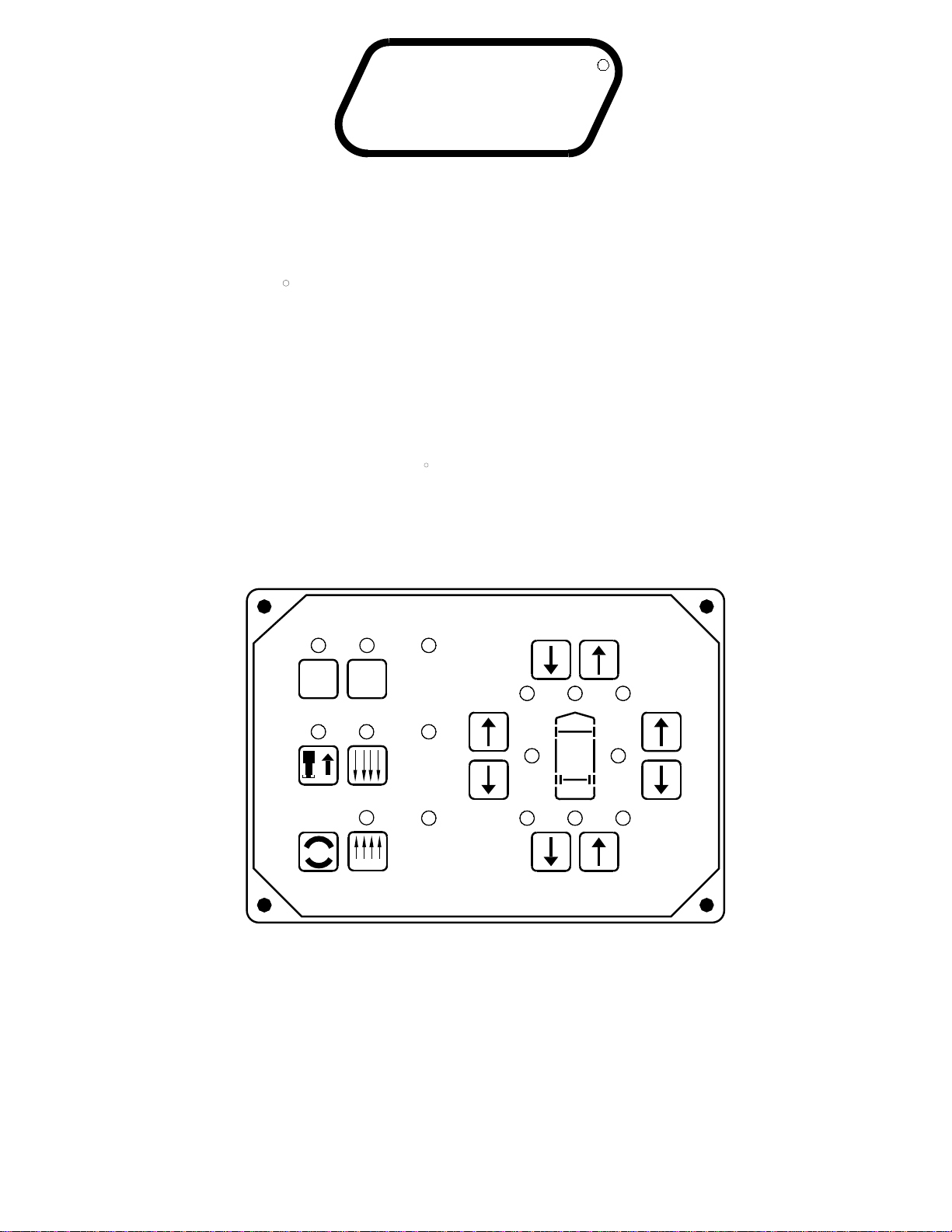
AUTOMATIC AIR OPERATION
the ignition is in the "ON" or "ACC" position, the four red
will begin. The system will first exhaust air from all the air
SYSTEM ACTIVE LIGHT will start flashing and air leveling
3. Press the "AIR" button a second time. The LEVELING
vehicle should not be moved when these lights are on.
that the height control valves have been locked out. The
WARNING lights on the panel will come on. This indicates
LEVELING SYSTEM ACTIVE LIGHT will glow steady. When
2. Press the "AIR" button once to enter the air mode. The
"NOT IN PARK/BRAKE" light will be on while the "AIR"
the panel will not turn on if the park brake is not set. The
required for leveling.
will level with the engine shut off, however more time will be
This will provide a better air supply for leveling. The vehicle
Leaving the engine running during leveling is recommended.
turned on if the ignition is in the "ON" or "ACC" position.
and set the park brake. The air leveling system can only be
1. Place the transmission in the proper position for parking
started, the ignition can be moved to the "OFF" position
position to use the "AIR" button. Once the operation is
button is being pushed.
NOTE: If the ignition key is in the "ON" or "ACC" position,
NOTE: The ignition must be in the "ON" or "ACC"
4. When all four yellow level lights are out, the LEVELING
SYSTEM ACTIVE LIGHT will stop flashing and start pulsating
dimly. The Leveling System is now in the SLEEP MODE.
NOTE: After the ignition and all room extension KEY
SWITCHES are turned OFF, the CAN Network stays active
for 10 minutes before shutting down. Leveling System
and the operation will continue. All jacks must be fully
NOTE: Only one or two yellow LEVEL SENSING lights
may be ON at one time.
The vehicle’s engine/ignition may now be turned OFF.
touch panel lights will stay ON during this time and go
out when the CAN Network shuts down. If the Leveling
System is in the SLEEP MODE when the Network shuts
down, the computer will stay ON. The Leveling System
touch panel lights will all be OFF, but the Leveling
System will still be in the SLEEP MODE.
5. 30 minutes after the Leveling System enters the SLEEP
MODE, the computer will monitor the LEVELING SENSING
UNIT for one minute. If no leveling is needed, the computer
will continue to monitor the LEVELING SENSING UNIT
every 30 minutes. No light will be seen on the Touch Panel.
6. If the vehicle needs to be re-leveled, the CAN Network will
become active. The Leveling System touch panel lights will
come ON during the leveling procedure. The LEVELING
SYSTEM ACTIVE LIGHT will flash. One or two yellow
LEVELING LIGHTS will be ON. When the yellow LEVELING
LIGHTS are all out, the LEVELING SYSTEM ACTIVE LIGHT
will stop flashing and start pulsating dimly. The Leveling
System will remain in the SLEEP MODE with the computer
monitoring the LEVELING SENSING UNIT every 30 minutes,
re-leveling the vehicle as needed.
"ON" position.
pushed or the park brake is released, if the ignition is in the
7. The SLEEP MODE will continue until the "OFF" button is
system re-levels the vehicle.
the touch panel lights OFF. This happens every time the
after re-leveling the vehicle and then shut down, turning
NOTE: The CAN Network will stay active for 10 minutes
is active until the vehicle is leveled with all yellow LEVEL
The "EXCESS SLOPE" light will be on whenever the network
out. The "EXCESS SLOPE" light will be on whenever
light will come on. The LEVEL LIGHT indicator light will go
if a LEVEL SENSING light is still on, the "EXCESS SLOPE"
vehicle for approximately 30 minutes. After the 30 minutes,
The system will attempt to level the
the network is active.
indicator lights off.
EXCESS SLOPE:
The system will only return to the TRAVEL MODE if the
"STORE" button is pushed or the park brake is released.
In either case, the ignition key must be in the "ON"
position.
retracted to use the "AIR" button.
bags to lower the vehicle. The system will then add air to
bags to raise the low side first, if needed, then raise the
low end, if needed.
If no yellow level lights are on when the air button is pushed
the second time, the system will still exhaust all air from all
the air bags. If a yellow light is on after the air has been
exhausted, the system will level the vehicle by adding air
to the necessary air bags to turn the yellow lights off. If no
yellow lights are on after the air is exhausted, the system
will go directly into the sleep mode.

OPERATING PROCEDURES
MP34.3702
01MAR10
MANUAL AIR OPERATION
NOTE: The ignition must be in the "ON" or "ACC"
position to use the "AIR" button. Once the operation
is started, the ignition can be moved to the "OFF"
NOTE: If the "NOT IN PARK/BRAKE" light is on,
NOTE: If the "DUMP" or "RAISE" buttons are pushed
the leveling system cannot be turned on.
before leveling the vehicle front to rear.
The yellow LEVEL
indicator light indicates that side or end is low. When all yellow
lights are out the vehicle is level. Try leveling the vehicle by
while manually leveling the vehicle with air and the
ignition is in the "ON" position, the system will latch
into the dump or raise mode until the "EMERGENCY
STOP" button is pushed or the ignition is turned off.
4. Turn the ignition to the "OFF" position.
5. Turn the system off.
"DUMP" AND "RAISE" FUNCTIONS
CAUTION: REREAD CAUTIONS ON THE FIRST
PAGE OF THIS MANUAL. THE VEHICLE MAY DROP OR
RAISE AND/OR MOVE FORWARD OR BACKWARD
WITHOUT WARNING CAUSING INJURY OR DEATH.
THE AIR SUSPENSION IS AT THE PROPER
DO NOT OPERATE THE VEHICLE UNLESS
RESPONSIBILITY TO CHECK THAT THE VEHICLE
IS AT PROPER RIDE HEIGHT BEFORE TRAVELING.
CAUTION: IT IS THE OPERATOR’S
The "RAISE" and "DUMP" buttons can be used at any time
the network is active. The park brake does not have to be on.
If the ignition is in the "ON" position and the park brake is off,
the "RAISE" or "DUMP" buttons will latch in. The vehicle will
raise or lower completely and stay in that position. The vehicle
can not return to ride height until the "STORE" button or the
"OFF" button is pushed or the vehicle exceeds 10 M.P.H,
position and the operation will continue. All jacks
The "DUMP" and "RAISE" functions are provided for operator
convenience for purposes such as dumping the air
suspension when parked.
Leave the engine running if the "RAISE" function is to be
used. The park brake does not have to be set to use the
"DUMP" or "RAISE" buttons.
HEIGHT FOR TRAVEL.
putting the system in the TRAVEL MODE.
(up arrow) button to raise the low side or end.
lights). If a level position is not achieved use the RAISE1. Place the transmission in the proper position for parking
and set the park brake. The air leveling system can only be
turned on if the ignition is in the "ON" position. Running the
vehicle engine during leveling is recommended. This will
provide a better air supply for leveling. The vehicle will level
with the engine shut off, however more time will be required
for leveling.
2. Press the "AIR" button once to enter the air mode. The
LEVELING SYSTEM ACTIVE LIGHT indicator light will glow
steady. When the ignition is in the "ON" position, the four red
WARNING lights on the panel will come on. This indicates
that the height control valves have been locked out. The
vehicle should not be moved when these lights are on.
IMPORTANT: If the ignition is ON and the park brake is
OFF, the "DUMP" and "RAISE" features will latch in and
remain on. If the vehicle exceeds 10 MPH, the "DUMP"
or "RAISE" functions will automatically turn off and the
system will return to the TRAVEL MODE. If the park
brake is set, the "STORE" button must be pushed
before the vehicle can return to ride height.
If the ignition is in the "OFF" position the "RAISE" and "DUMP"
buttons will not latch in. The vehicle will remain in the position
it was when the button was released. The vehicle can return
to ride height when the ignition is turned to "ON" if the park
brake is released or the "STORE" button is pushed.
lowering the high side or end (opposite of the lit yellow level
3. The vehicle can now be leveled using the RAISE (up arrow)
and LOWER (down arrow) buttons on the right half of the
panel in conjunction with the yellow LEVEL indicator lights.
Any side to side leveling should be done, if needed,
NOTE: In either manual or automatic leveling when
either front air manifold air bag pressure switch is on
a front lower procedure is halted. When either rear air
manifold air bag pressure switch is on, a rear lower
procedure is halted. Air bag pressure switches will
not interfere with either a right or left lower procedure.
DO NOT operate the vehicle for extended distances
unless the air suspension is at the proper height for
travel. The vehicle can not return to ride height until
the "OFF" button is pushed or the vehicle exceeds
10 MPH, putting the system in the TRAVEL MODE.
must be fully retracted to use the "AIR" button.
The "RAISE" and "DUMP" buttons will not function if the
light above the "STORE" button is flashing, if the air
leveling system is in the SLEEP mode, or if the vehicle
is moving more than approximately 10 mph.

SENSING UNIT MAINTENANCE/SERVICE
SENSING UNIT ADJUSTMENT / WITHOUT ADJUSTING ENHANCEMENT SWITCH
To adjust the sensing unit, first the vehicle must be level. Either
position the vehicle on a level surface or use the leveling system
to manually level the vehicle. It is recommended to use the
vehicle trim line to determine level. An alternative would be to
use a small bubble level. If using a bubble level, the level should
The Sensing Unit is mounted inside the Control Box. The
Control Box is mounted to the power unit/valve assembly.
NOTE: If opposing LED’s are lit, there is a problem with
the Sensing Unit.
If LED (A) is lit: Turn the adjustment screw COUNTER
CLOCKWISE until the LED is off.
If LED (C) is lit: Turn the adjustment screw CLOCKWISE
until the LED is off.
If LED (B) is lit: Turn the adjustment nut COUNTER
CLOCKWISE until the LED is off.
until the LED is off.
If LED (D) is lit: Turn the adjustment nut CLOCKWISE
ADJUSTMENT
NUT (5/16" OLD) - (1/2" NEW)
TOP VIEW - SENSING UNIT
ADJUSTMENT SCREW
D
C
A
B
CONTROL
BOX WALL
LED’S - LOCATION SIDE VIEW - CONTROL BOX
MAY BE DIFFERENT
09NOV10
MP44.1512
There are four LED’s on the Sensing Unit, A,B,C and D. Refer
to the drawing below. The Sensing Unit is adjusted by turning
the adjustment nut to turn out LED’s B and D. The adjustment
screw will turn out LED’s A and C. If the adjustment nut has
to be turned more than 1/2 flat or the adjustment screw has to
be turned more than 3/4 turn to turn the LED out, there may
be a problem with the Sensing Unit or the mounting of the
Control Box. If two LED’s are on, it is best to make the B-D
adjustments first, then hold the adjustment nut from moving
ADJUSTMENT NUT (5/16" OLD) - (1/2" NEW)
while making the A-C adjustment.
ADJUSTMENT
SCREW (Phillips or 1/4")
NUT (7/8" or 3/4")
ADJUSTMENT
IMPORTANT: When all 4 LED’s are off, move the
vehicle to an unlevel position so one or two yellow
lights are on. Level the vehicle according to the yellow
LEVEL lights. Recheck the level. If more adjustment is
needed, DO NOT try to adjust the sensing unit until the
yellow level lights go out, instead just "tweak" the
sensing unit, ignoring the LED’s on the sensing unit.
Example: After the initial adjustment and releveling
the vehicle, the front is still low. This means the front
yellow level light is turning off too soon. Determine
which sensing unit light is the front light, A-B-C or D.
Move the adjustment for that light very, very, slightly in
the OPPOSITE direction that is given in the above
instructions for LED’s A, B, C, and D. This will allow
the front yellow light to stay on slightly longer to bring
the front up more. Again, unlevel the vehicle then
relevel the vehicle using the yellow level lights on the
touch panel. Recheck with a level. Repeat the
"tweaking" process until the system levels the vehicle
properly.
NUT (7/8" or 3/4")
ADJUSTMENT
SENSING UNIT ACCURACY TOLERANCE
The sensing unit has an accuracy tolerance of ± 5.4 inches front to rear and
INSTRUCTION SHEET
± 1 inch side to side on a 36 foot vehicle. Typical leveling results will be better.
(OLD STYLE)
(OLD STYLE)
7/8, 3/4, 1/2, 5/16 or 1/4 sizes will be needed.
screw driver or sockets w/driver or box end wrenches of
adjustments to the Sensing Unit are needed. A Phillips
are yellow LEVEL lights lit on the Touch Panel, manual
Touch Panel, the sensing unit is properly adjusted. If there
With the vehicle level , if there are no yellow lights lit on the
be placed on a flat surface close to the mounting location of
the control box/sensing unit.

SENSING UNIT MAINTENANCE/SERVICE
SENSING UNIT ADJUSTMENT / WITH ADJUSTING ENHANCEMENT SWITCH
To adjust the sensing unit, first the vehicle must be level. Either
position the vehicle on a level surface or use the leveling system
to manually level the vehicle. It is recommended to use the
vehicle trim line to determine level. An alternative would be to
use a small bubble level. If using a bubble level, the level should
The Sensing Unit is mounted inside the Control Box. The
adjusting enhancement switch is on the same side of the
NOTE: If opposing LED’s are lit, there is a problem with
the Sensing Unit. If lit LEDs on the sensing unit plate do
If LED (A) is lit: Turn the adjustment screw COUNTER
CLOCKWISE until the LED is off.
If LED (C) is lit: Turn the adjustment screw CLOCKWISE
until the LED is off.
If LED (B) is lit: Turn the adjustment nut COUNTER
CLOCKWISE until the LED is off.
until the LED is off.
If LED (D) is lit: Turn the adjustment nut CLOCKWISE
ADJUSTMENT
NUT 1/2"
TOP VIEW - SENSING UNIT
ADJUSTMENT SCREW
D
C
A
BSIDE VIEW - CONTROL BOX
MAY BE DIFFERENT
09NOV10
MP44.1513
There are four LED’s on the Sensing Unit, A,B,C and D. Refer
to the drawing below. The Sensing Unit is adjusted by turning
the adjustment nut to turn out LED’s B and D. The adjustment
screw will turn out LED’s A and C. If the adjustment nut has
to be turned more than 1/2 flat or the adjustment screw has to
be turned more than 3/4 turn to turn the LED out, there may
be a problem with the Sensing Unit or the mounting of the
Control Box. If two LED’s are on, it is best to make the B-D
adjustments first, then hold the adjustment nut from moving
ADJUSTMENT NUT
while making the A-C adjustment.
ADJUSTMENT
SCREW (Phillips or 1/4")
SENSING UNIT ACCURACY TOLERANCE
The sensing unit has an accuracy tolerance of ± 5.4 inches front to rear and
INSTRUCTION SHEET
± 1 inch side to side on a 36 foot vehicle. Typical leveling results will be better.
1/2", or 1/4" sizes will be needed.
screw driver or sockets w/driver or box end wrenches of
adjustments to the Sensing Unit are needed. A Phillips
are yellow LEVEL lights lit on the Touch Panel, manual
Touch Panel, the sensing unit is properly adjusted. If there
With the vehicle level , if there are no yellow lights lit on the
be placed on a flat surface close to the mounting location of
the control box/sensing unit.
control box as the sensing unit adjustment assembly.
The ignition (motorized units) or master power switch (towable
units) must be on to adjust the sensing unit. Before adjusting
the sensing unit, move the "adjusting enhancement switch"
from the "NORMAL" (110) position to the "OVERRIDE" (220)
position. This will make the sensing unit very sensitive.
The LEDs on the sensing unit plate may "jump" around while
adjusting the sensing unit. Allow the lights to settle down
after each adjustment. Small, gentle movements will work
best when moving the sensing unit adjustment nut or screw.
When all four LEDs are off, move the enhancement switch
back to the "NORMAL" (110) position. When the adjustment is complete, move the vehicle to an
out of level position and level the vehicle according to the
yellow level lights on the touch panel. If necessary, go
through the adjustment procedure again.
not match the yellow level lights on the touch panel, the
control box is not properly oriented. Contact HWH
Corporation for assistance.
CONTROL BOX WALL
LEDs - LOCATION
assembly may may be in a
different position due to control
box style or orientation.
LEVEL SENSOR
NORMAL
OVERRIDE
ENHANCEMENT SWITCH
ADJUSTING
NOTE: Sensing unit adjustment

HYDRAULIC LINE CONNECTION DIAGRAM
MP64.3916
01MAR10
(WITH 4 STRAIGHT-ACTING JACKS)
PUMP/MANIFOLD
ASSEMBLY
SHUTTLE
VALVE
LEFT
FRONT RIGHT
FRONT
RIGHT
REAR
LEFT
REAR
2000 SERIES LEVELING SYSTEM
VELOCITY VALVE
NOTE: SOME
MANIFOLDS
ARE EQUIPPED
WITH VELOCITY
VALVES
50PSI
PRESSURE
SWITCH
NUTS OR T-HANDLES, READ AND UNDERSTAND
IN OPERATOR’S INSTRUCTIONS.
PROCEDURE FOR MANUAL JACK RETRACTION
BEFORE OPERATING VALVE RELEASENOTE:
PRESSURE
SWITCH
3000PSI
BREATHER
CAP
NUT LOCATED
WITH RELEASE
LARGE VALVE
UNDER
PLASTIC PLUG

HYDRAULIC
POWER UNIT
M
RELIEF VALVE
RETURN PRESSURE
SOLENOID MANIFOLD
ASSEMBLY
CHECK
VALVE
INNER
CHECK
VALVE
OUTER
SOL.VALVE
LR SOL.VALVE SOL.VALVE
RFLF
PRESSURE/RETURN
SHUTTLE VALVE
50 PSI
SWITCH
*JACK
PRESSURE
SWITCH
JACK
CYLINDER
LEFT REAR RIGHT REAR
RIGHT
FRONT
LEFT
FRONT
MP64.4000
02MAR10
*3000 PSI
SWITCH
LEVELING SYSTEM
ROOM EXTENSION
MANIFOLD LOCATED HERE
WHEN APPLICABLE
RR
SOL.VALVE
* USED ON AUTOMATIC SYSTEMS ONLY
NOTE: 50 PSI PRESSURE SWITCH
MAY NOT BE USED ON ALL 625 MANIFOLDS.
3500 P.S.I.
BI-AXIS LEVELING WITH STRAIGHT-ACTING JACKS
625 - 625S OR 2000 SERIES
HYDRAULIC SCHEMATIC DIAGRAM
800 PSI TO SHIFT

AIR LINE CONNECTION DIAGRAM
FRONT / DRIVE AND TAG AXLES
02MAR10
MP74.0662
HCV
FRONT AIR
MANIFOLD
LINE FROM HEIGHT
CONTROL VALVE LINE FROM HEIGHT
CONTROL VALVE
LF AIR BAG
PRESS SW 20 PSI
AIR SUPPLY
AXLE
DRIVE
AXLE
FRONT
FRONT
AXLE
DRIVE
MANIFOLD
SYSTEM
AIR PRESS
SWITCH
85 PSI
RR AIR BAG
PRESS. SW 20 PSI
AIR BAG
PRESS SW 20 PSI
RF AIR BAG
AIR BAG
LINE TO
HCV
SEE AIR LINE
CONNECTION
DIAGRAM AIR
COMPRESSOR
SEE SPECIFIC MANIFOLD
DIAGRAMS FOR CONNECTION
INFORMATION MANIFOLDS ARE
PRE-WIRED AND CONNECTIONS
ARE LABELED. RIGHT AND LEFT
CONNECTIONS MUST BE
PROPERLY MAINTAINED.
HWH AUXILIARY
AIR COMPRESSOR
PING
TANK
AXLE
TAG
TAG
DUMP
VALVE
NOTE: HWH ONLY SUPPLIES THE FRONT
AND DRIVE AXLE AIR MANIFOLDS ALONG
WITH AN AUXILIARY AIR COMPRESSOR.
ALL OTHER EQUIPMENT IS BY THE
VEHICLE OR CHASSIS MANUFACTURER.
HCV HCV
FROM CHASSIS AIR SUPPLY
PRESSURE PROTECTION VALVE
SW 20 PSI
PRESS.
NOTE: TAG DUMP
VALVES MAINTAIN
20 PSI AIR PRESSURE
IN TAG AIR BAGS
WHEN TAG AXLE
AIR IS DUMPED
LR AIR BAG
RS TAG
AXLE
AIR
BAG
AIR
BAG
AXLE
LS TAG
TANK
PING
VALVE
DUMP
TAG
*PROPORTIONING
VALVES FOR
TAG AXLE
**
PRESSURE
PROTECTION
MANIFOLD
AXLE AIR
BAG
LS DRIVE AXLE AIR
BAG
RS DRIVE

EXH EXH
FRONT MANIFOLD ASSEMBLY
EXHEXH RF HCVLF HCV TRAV.
LOWER
RAISE
TRAV.
LOWER
RAISE
4-POINT LEVELING SYSTEM SCHEMATIC
PRESSURE SWITCHES FRONT AND REAR
MP74.2640
01MAR10
RAISE
LOWER
TRAV.
RAISE
LOWER
TRAV.
EXH EXH
AIR LINE CONNECTION DIAGRAM
BYPASS
VALVE
VALVE
BYPASS
FRONT AXLE
AIR BAG FRONT AXLE
AIR BAG
AIR BAG PRESSURE
SWITCHES RIGHT
AND LEFT 20PSI
NOTE: HWH ONLY SUPPLIES THE FRONT AND DRIVE AXLE AIR
MANIFOLD ASSEMBLIES ALONG WITH THE HWH AUXILIARY AIR
COMPRESSOR. ALL OTHER EQUIPMENT AND PLUMBING IS
SUPPLIED BY THE VEHICLE OR CHASSIS MANUFACTURER.
SEE AIR LINE CONNECTION DIAGRAM
COMPRESSOR SCHEMATIC
HWH AUXILIARY AIR COMPRESSOR
DRIVE MANIFOLD ASSEMBLY
EXH
EXHEXH
LR HCV
BYPASS
VALVE
LOWERLOWER
RAISERAISE
TRAV.TRAV.
AIR BAG PRESSURE
SWITCHES RIGHT
AND LEFT 20PSI
LOWERLOWER
RAISERAISE
TRAV.TRAV.
EXHEXH
BYPASS
RR HCV
VALVE
EXH
TANK
PING PING
TANK
TAG AXLE
AIR BAG TAG AXLE
AIR BAG
TAG AXLE PROPORTIONING VALVES
TAG AXLE DUMP VALVES
PROTECTION
MANIFOLD
PRESSURE FROM AIR PRESSURE
PROTECTION VALVE
NOTE: TAG AXLE DUMP VALVES WILL MAINTAIN
A MINIMUM OF 20 PSI AIR PRESSURE IN THE TAG AXLE
AIR BAGS WHEN THE TAG AXLE AIR BAGS ARE DUMPED
DRIVE
AXLE
AIR BAG AIR BAG
AXLE
DRIVE
SYSTEM
AIR PRESS.
SW 85PSI

FRONT AIR SOLENOID MANIFOLD CONNECTIONS
6 VALVE WITH TWO PRESSURE SWITCHES
ABBABABABABABABA
BA BA BA BA BA BA BA BA
RS
TRAVEL
LS
LOWER
RS
PSW
RS
RAISE
RS
LOWER
LS
RAISE
LS
TRAVEL
LS
PSW
RS
TRAVEL
LS
LOWER
RS
PSW
RS
RAISE
RS
LOWER
LS
RAISE
LS
PSW
LS
TRAVEL
REAR
LEFT SIDE RIGHT SIDE
PRESSURE
SWITCH-20 PSI
3.400"
PRESSURE
SWITCH-20 PSI
AIR BAG
LINE TO LR LINE TO RR
AIR BAG
EXHAUST
PORT EXHAUST
PORT
LINES FROM HEIGHT
CONTROL VALVES -
TWO MAY BE TEE’D
TOGETHER IF ONE
HCV IS USED.
AIR
SUPPLY
RIGHT RAISE
SOLENOID VALVE (LEFT
VALVE NOT SHOWN)
VALVE NOT SHOWN)
SOLENOID VALVE (LEFT
RIGHT LOWER
VALVE NOT SHOWN)
SOLENOID VALVE (LEFT
RIGHT TRAVEL
IMPORTANT: LEFT AND RIGHT
CONNECTIONS MUST BE MAINTAINED
AS SHOWN. GROUND SUPPLY WIRES
FOR AIR PRESSURE SWITCHES AND
AIR SOLENOID VALVES CANNOT
BE INTERCHANGED.
CHECK
VALVE (2)
VIEW
(2 LEFT AND RIGHT)
LINE TO AIR BAGS
20 PSI (2 LEFT AND RIGHT)
PRESSURE SWITCH
(2 LEFT AND RIGHT)
EXHAUST PORTS
TEED TOGETHER IF ONE
CONTROL VALVE (MAY BE
LINE FROM HEIGHT
MOUNTING HOLES
AIR SUPPLY
HCV IS USED) VIEW
RIGHT SIDE
NOTE: SOLENOID VALVES AND
AIR LINE CONNECTIONS ARE
LABELED.
01MAR10
MP74.2641

REAR AIR SOLENOID MANIFOLD CONNECTIONS
6 VALVE WITH THREE PRESSURE SWITCHES
ABBABABABABABABABA
BA BA BA BA BA BA BA BA AB
RS
TRAVEL
LS
LOWER
RS
PSW
RS
RAISE
RS
LOWER
LS
RAISE
LS
TRAVEL
LS
PSW
SYS
PSW
RS
TRAVEL
LS
LOWER
RS
PSW
RS
RAISE
RS
LOWER
LS
RAISE
LS
PSW
LS
TRAVEL
SYS
PSW
REAR
LEFT SIDE RIGHT SIDE
PRESSURE
SWITCH-20 PSI
SWITCH-85 PSI
PRESSURE
3.400"
PRESSURE
SWITCH-20 PSI
AIR BAG
LINE TO LR LINE TO RR
AIR BAG
EXHAUST
PORT EXHAUST
PORT
LINES FROM HEIGHT
CONTROL VALVES -
TWO MAY BE TEE’D
TOGETHER IF ONE
HCV IS USED.
AIR
SUPPLY
RIGHT RAISE
SOLENOID VALVE (LEFT
VALVE NOT SHOWN)
VALVE NOT SHOWN)
SOLENOID VALVE (LEFT
RIGHT LOWER
VALVE NOT SHOWN)
SOLENOID VALVE (LEFT
RIGHT TRAVEL
CHECK
VALVE (2)
VIEW
(2 LEFT AND RIGHT)
LINE TO AIR BAGS
20 PSI (2 LEFT AND RIGHT)
PRESSURE SWITCH
(2 LEFT AND RIGHT)
EXHAUST PORTS
TEED TOGETHER IF ONE
CONTROL VALVE (MAY BE
LINE FROM HEIGHT
MOUNTING HOLES
AIR SUPPLY
HCV IS USED) VIEW
RIGHT SIDE
SWITCH-85 PSI
PRESSURE
NOTE: SOLENOID VALVES AND
AIR LINE CONNECTIONS ARE
LABELED.
01MAR10
MP74.2642
BE INTERCHANGED.
AIR SOLENOID VALVES CANNOT
FOR AIR PRESSURE SWITCHES AND
AS SHOWN. GROUND SUPPLY WIRES
CONNECTIONS MUST BE MAINTAINED
IMPORTANT: LEFT AND RIGHT

AIR LINE CONNECTION DIAGRAM
12 VOLT RELAY AIR FILTER
13APR10
MP74.4622
BATTERY
GROUND
FROM +12
FLOW
RELIEF VALVE
(110 PSI)
AIR SOLENOID
TO HWH AIR
+12 CONTROL
COMPRESSOR
FROM HWH AIR
LEVELING MANIFOLDS
NORMALLY OPEN
HWH AIR COMPRESSOR
HARNESS
15 AMP
FUSE
VALVE
CHECK
Other manuals for 2000 SERIES
8
Other HWH Service Equipment manuals