manuals.online logo
Brands
  1. Home
  2. •
  3. Brands
  4. •
  5. Hy-Gain
  6. •
  7. Antenna
  8. •
  9. Hy-Gain 18AVQII User manual

Hy-Gain 18AVQII User manual

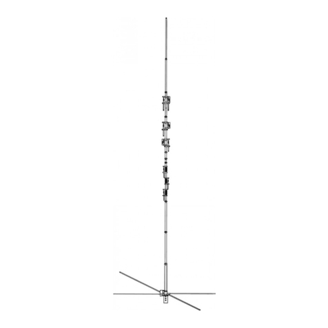
Model 18AVQII
Five Band Vertical Antenna
10, 15, 20, 40, 80 Meter
308 Industrial Park Road
Starkville, MS 39759
(662) 323-9538 Fax: (662) 323-5803
INSTRUCTION MANUAL
General Description
The Hy-Gain 18AVQII is an omni-directional, vertical radiator that operates on the 10,
15, 20, 40, and 80 meter amateur bands. The system will work against earth ground or a
resonant radial system when mounted above ground. You can make your own radial
system following the manual, or use the Hy-Gain 14RMQ Radial System Kit available at
your Hy-Gain dealer.
The antenna can be used for either Phone or CW with either a ground or roof mount. It
can also be tuned to mid-band for use with either Phone or CW. In either case, the SWR
bandwidths of the antenna are broad enough that the antenna will operate at an SWR of
2:1 or less on the 10, 15, 20, and 40 meter bands. The antenna will radiate on the 80
meter band with a limited bandwidth. The 18AVQII is supplied with stainless steel
hardware and element clamps for all electrical and most mechanical connections.
Theory of Operation
The use of heavy duty "Hy-Q Traps" provides automatic band selection. The Hy-Q Traps
are parallel resonant circuits which isolate the various sections of the antenna and give
quarter wavelength resonance on all bands. The top loading coil is used for operation on
the 80 meter band while the overall height of the antenna remains less than 20 feet.
WARNING: When installing your antenna, take extreme care to avoid any accidental
contact with power lines or overhead obstructions. Failure to exercise this care could
result in serious or fatal injury.
NOTE: If the terminals of the input connector are checked with an ohmmeter, they will
show a direct short. This is normal! The matching coil in the antenna base puts the entire
system at DC ground, but presents a 50 ohm load impedance to RF energy.
Choosing a Site
The 18AVQII can be mounted on the ground, on a rooftop, or on a mast. The antenna
should be secured using non-conducting guy ropes if the 80 meter loading coil is
installed. When choosing an installation site be sure to allow sufficient space for these
guy ropes.
Radial System and Grounding
When mounting the antenna more than three feet above ground, a resonant radial system
must be used, such as Hy-Gain's 14RMQ Radial System Kit. If the antenna is roof
mounted and the roof space is too small for a radial system, you can droop the radials
over the edge of the roof at almost any angle without seriously changing the performance
of the antenna. The radial system must be insulated from the roof and connected to a
good ground or lightning protection. See Figure 5. For best performance, the 18AVQII
should be ground-mounted clear of building and other structures. When the antenna is
ground-mounted, a radial system is sometimes not needed. In most areas, where soil
surface conductivity is poor and a good ground plane is not possible, lay out ground
radials to improve the efficiency of your antenna.
Installation of Radials
There is no need to make radials exactly ¼ wavelength long for the 18AVQII. In fact, the
only case where you should have ¼ wavelength radials would be for approximately 90
radials. This differs rather dramatically from the case of the Ground Plane antenna where
resonant radials are installed above ground. Since the radials of a ground-mounted
vertical are actually on, if not in, the ground, they are coupled by capacitance or
conduction to the ground, thus resonance effects are not important.
Basically, the function of radials is to provide a low-loss return path for ground currents.
The reason that short radials are sufficient when few are used, is that at the perimeter of
the circle to which the ground system extends, the radials are sufficiently spread apart.
Most of the return currents are already in the ground between the radials rather then in the
radials themselves. As more radials are added, the spaces between them are reduced and
longer lengths help to provide a path for currents still farther out. Since the 18AVQII is a
multi-band, vertical antenna, the radial system should be optimized on the lowest
frequency you plan to use. Higher frequencies will benefit equally from the ground
system, while lower frequencies will not show as much improvement.
To determine the optimum radial installation for your 18AVQII, you must first decide
what the limiting factor for your installation will be. The list below includes factors that
need to be considered.
1. Cost of radial wires
2. Area available for radials
3. Efficiency of your antenna
Use figure 1 below to design a radial system to the optimum length for your preferred
operating band.
80
M
40M
20M
15M
10M
80M
40M
20M
15M
10M
33’
33’
11’ 4”
11’ 4”
8’ 4”
8’ 4”
133’
133’
16’ 6”
16’ 6”
Figure 1
Optimum Radial Lengths, Dimensions from Base to Insulator
Assembly and Installation
Before you begin, read the instructions and study the illustrations. Compare the parts
against the Parts List at the end of this manual. Decide where to mount your antenna
(rooftop or ground) and what mode of transmission you will use (Phone, CW or Mid-
Band). Take special notice of the dimensions in Figure 2. The SWR charts will help you
decide which dimensions to choose. See Figure 8.
80METER
CAPACITACESPOKES
40 METER
CAPACITACESPOKES
80 METERLOADINGCOIL
3
5
18-25-28
7-M2
1-25-287
11-10 Meter Trap
14-15 Meter Trap
15-20 Meter Trap
17-25-28
9-M4
16-20-23
8-M3
17-25-28
CW PH
PH
MB
26”
29”
32”
12” 12” 12 1/4”
8 3/4” 8 3/4”8 3/4”
14.5” 13.5” 13”
CW MB
(Ground Mount)
(Ground Mount)
Item No. Description
2 Base Assembly, 18AVQII
4 Tube, M, 1 1/4” x 48” slotted
5 Insulator, upper
7 Tube, M2, 1 1/8” X 52”
8 Tube, M3, 1” x 8”
9 Tube, M4, 1” X 6 ½”
10 Tube, M5, 7/16” x 56”
11 Trap, 10 Meter
14
15
16 Clamp, Tubing, No. 6
17
18
Trap, 15 Meter
Trap, 20 Meter
Clamp, Tubing, No. 10
Clamp, Tubing, No. 16
Antenna Assembly Dimensions
20.5” 22” 22.5”
Figure 2
Tubing
Select the proper size tube clamps as shown in the chart. When installing the clamps,
place the clamp near the tube end with the top of the clamp over the slot in the tube as
shown in Figure 2. After adjustment of the tubing lengths, tighten the clamp with a 5/16
inch nut driver, socket, or open end wrench until the tubing will not twist or telescope.
DO NOT over-tighten!
Figure 3 Tubing Clamps
CAUTION: All of the antenna dimensions must be set on the mode chosen - all CW, all
mid-band or all phone. Mixing dimensions in an attempt to improve another mode on
certain bands will only degrade performance on all bands. Refer to Figure 2 in
assembling the main portion of the antenna.
M1 and M2 Section
Put a #16 tubing clamp (Item No. 18), un-tightened, over the M1 section (Item No. 4)
(the base is attached to it already). Slip the 1 1/8" x 52" M2 section (Item No. 7) into the
top of the M1 and set the M2 at dimension 'A', as shown in Figure 1. Slide the clamp into
place around the top of the M1 and tighten it just enough to keep the M2 from skipping.
It will be fully tightened later.
10-Meter Trap
Put an un-tightened #10 Tubing clamp (Item No. 17) over the M2 section, then slip the 10
meter trap (Item No. 11), bottom first, into the M2 section. (There is a plastic cover on
the top of all three parts.) Set the trap at dimension "C", as shown in Figure 1. Slip the
clamp into place around the top of the M2 section and tighten it just enough to keep the
trap from slipping. It will be fully tightened later.
15-Meter Trap and M3 Section Assembly
Place two, un-tightened #10 tubing clamps (Item No. 17) over the 1" x 8" long M3
section (Item No. 8). Slide the M3 section part way over the upper end of the 10-meter
trap, then slide the lower end of the 15-meter trap (Item No. 14) into the M3 section. Set
dimension "C", as shown in Figure 1, and locate the M3 so that it is equally spaced
between the two traps. Tighten the clamps around the ends of the M3 just enough to keep
parts from slipping. They will be fully tightened later.
20-Meter Trap and M4 Section Assembly
Assemble these two parts like you did the M3 and the 15-meter trap. Use two more #10
tubing clamps, the 1" x 6 1/2" long M4 section (Item No. 9) and the 20-meter trap (Item
No.15).
NOTE: There is a threaded metal insert in one end of the M5 section which will accept
the #10-24 x 1" bolt (Item No. 20), which will hold the top hat in place. The end with the
insert must be at the top.
M5 Section
Put a #6 tubing clamp (Item No. 16), un-tightened, over the swaged end of the 20- meter
trap. Slip the 7/16" x 56" long M5 section (Item No. 10) into the swaged end of the trap
and set dimension "E", as shown in Figure 1. Slide the clamp in place around the top of
the swaged end of the trap tube and tighten it just enough to keep the M5 from slipping. It
will be fully tightened later.
Recheck all dimensions. Tighten all of the compression clamps securely in place.
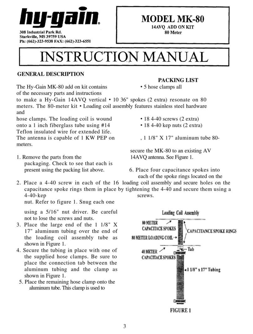
Top Loading Coil Assembly
1. Remove the loading coil parts from the separate packaging. Check to see that
each is present using the packing list at the end of this instruction manual.
2. Place a 4-40 screw in each of the 16 holes on the capacitance spoke rings and secure
them using a 4-40-kep nut. Refer to figure 4. Snug each one using a 5/16” nut driver.
Be careful not to lose the screws and nuts.
3. Place the large end of the 1 1/8” X 17” aluminum tubing over the end of the loading
coil assembly tube as shown in Figure 4.
4. Secure the tubing in place with one of the supplied hose clamps. Be sure to place the
connection tab between the aluminum tubing and the clamp as shown in Figure 4.
5. Place the remaining hose clamp onto the aluminum tube. This clamp is used to secure
the MK-80 to an existing AV-14AVQ antenna. See Figure 4.
6. Place four capacitance spokes into each of the spoke rings located on the
loading coil assembly and secure them in place by tightening the 4-40 screws.
Loadin
g
Coil Assembl
y
80METER
CAPACITACESPOKES
40METER
CAPACITACESPOKES
80 METERLOADINGCOIL
1 1/8” x 17” Tubing
Tab
CAPACITANCESPOKE RINGS
Figure 4
Installing the Antenna
Refer to the mounting details in Figure 4 and 5 to install the completely assembled
antenna.
Figure 5 Antenna Installation
First mount the completed antenna on your mast (not supplied) as shown in Figure 5. Use
the two U-bolts, 5/16" nuts and 5/16" lock washers (Items Nos. 29, 31 and 30). Use three
(3) 1/4"-20 x 3/4" bolts, nuts and lock washers (Item No’s 24, 27 & 26) to attach the
insulator to the upper end of the mounting bracket.
If you are roof mounting your antenna, use four (4) sets of 1/4"-20 hardware for the
preceding step. Before tightening them, attach two adjacent radials to each set of
hardware as shown in Figures 3 and 5. If desired, you may use the four, 33 foot radial
system shown.
NOTE: If your antenna is mounted more than three feet above ground, a resonant system
must be added for proper operation.
The radial system can serve to guy the system if insulators are used at the proper lengths
shown. This system must be grounded for lightning protection. Connect a ground wire to
one U-bolt on the antenna base and run it to a buried, 8 foot (250 cm) ground rod by the
shortest route. If you are ground mounting your antenna, install it as shown in Figure 4.
You must install an 8 foot ground rod as shown.
CAUTION: Keep the radials out of reach of children or pets. They are HOT with RF
proportional to the power of the antenna.
Figure 6
Figure 7
Hooking Up the Antenna
1. Connect your coax (RG-213/U) to the SO-239 connector at the bottom of the mounting
bracket. (Coax not supplied.) Weather seal the coax connection with Coax- Seal© or an
equivalent to prevent moisture from shorting out the connection. Final Adjustment
(Optional Fine Tuning Of Your Installation)
2. Because every antenna installation is influenced by the soil conditions and the
proximity effect of nearby objects, the dimensions in the manual must be fine tuned to
put the antenna VSWR exactly where you want it on each band.
3. Beginning on 10 meters, make a VSWR curve checking the low end, center and high
end of the band. This will indicate if the antenna favors the low end or the high end as
installed.
4. The antenna operates progressively from 10 thru 40 meters. Even though you may not
be using 10 meters at the present time, 10 meters must be adjusted, because any
adjustment made between the base and the first trap automatically changes all of the
bands.
a. If it favors the low end, shorten the 10- meter adjustment one inch or no
more than 1 1/2 inches. Run another VSWR measurement. Now you will
have an indication of how far that distance moved the antenna in your
location.
Make what additional adjustments are indicated by the VSWR curve to put 10 meters
exactly on the portion of the band you desire as your center operating frequency.
b. If the antenna favors the high end, lengthen the dimension
correspondingly to move the antenna to a lower frequency as outlined
above.
5. Next, repeat this same procedure for 15 meters to put that band on frequency.
6. The same procedure is then used to set up the 20-meter band, as well as the remaining
bands available, depending upon the model involved.
7. Most verticals are monopole antennas or half of a dipole. For this reason, the soil
conditions, when the antenna is ground mounted, are important as it makes up the other
half of the antenna. When you roof mount the antenna, radials must be used as outlined in
the assembly instructions, to provide the other half of the antenna.
Lightning Protection
For maximum lightning protection, we recommend the use of a Hy-Gain LA-1 Lightning
Arrestor, available from your Hy-Gain dealer. Your antenna is now ready to use.
Figure 8
Parts List
Item
No. Part No. Description Qty.
2 871049 Base Assembly 1
4 190900 Tube, M1, 11/4 x 48", slotted 1
5 463056 Insulator, upper 1
6 523057 Screw, hex head, #10-24x1" 1
7 190303 Tube, M2, 11/8 x 52" 1
8 190603 Tube, M3, 1" x 8" 1
9 190605 Tube, M4, 1" x 6.5" 1
10 877157 Tube, M5, 7/16"x 56" 1
11 877132 Trap, 10 Meter 1
12 464723 Trap Cap, 7/8" x 15/8" 3
13 461466 Trap Spacer 4
14 877131 Trap, 15 Meter 1
15 877129 Trap, 20 Meter 1
16 358756 Clamp, Tubing No. 6 1
17 358757 Clamp, Tubing No. 10 5
18 358758 Clamp, Tubing No. 16 1
19 455624 Caplug, 1/8" dia 3
20 504069 Bolt, hex head, #10-24x1" 1
21 565697 Lockwasher, internal, #10 3
22 561165 Flatwasher, #10 4
23 555693 Nut, square, #10-24 1
24 505266 Bolt, hex head, 1/4 "-20 x 3/4" 4
26 562967 Lockwasher, internal, 1/4" 5
27 554099 Nut, Hex, 1/4-20 4
29 543792 U-Bolt, 5/16" x 15/8"x 21/4" 2
30 564792 Lockwasher, split 5/16 4
31 555747 Nut, hex, 5/16"-18 4
80 Meter Loading Coil Assembly Parts List
1 190315 Tube 1 1/8" x 20" SW 1
2 11-
18avqii-1 Loading Coil Assembly 1
3 810-0640-
27 36" spokes 10
4 872016 Parts Pack 1
5 656-
0375S 6-32" x 3/8" 18
6 705-
06325-k 6-32" kep nuts 18
7 74531105 Hose Clamp 5
8 Manual(18-AVQII) 1
hy-gain®LIMITED WARRANTY
hy-gain Warrants to the original owner of this product, if manufactured by hy-gain and
purchased from an authorized dealer or directly from hy-gain to be free from defects in
material and workmanship for a period of 12 months for rotator products and 24 months
for antenna products from date of purchase provided the following terms of this warranty
are satisfied.
1. The purchaser must retain the dated proof-of-purchase (bill of sale, canceled check,
credit card or money order receipt, etc.) describing the product to establish the
validity of the warranty claim and submit the original or machine reproduction of
such proof-of-purchase to hy-gain at the time of warranty service. hy-gain shall have
the discretion to deny warranty without dated proof-of-purchase. Any evidence of
alteration, erasure, or forgery shall be cause to void any and all warranty terms
immediately.
2. hy-gain agrees to repair or replace at hy-gain’s option without charge to the original
owner any defective product under warranty, provided the product is returned postage
prepaid to hy-gain.
3. Under no circumstances is hy-gain liable for consequential damages to person or
property by the use of any hy-gain products.
4. Out-of-warranty Service: hy-gain will repair any out-of-warranty product provided
the unit is shipped prepaid. All repaired units will be shipped COD to the owner.
Repair charges will be added to the COD fee unless other arrangements are made.
5. This warranty is given in lieu of any other warranty expressed or implied.
6. hy-gain reserves the right to make changes or improvements in design or manufacture
without incurring any obligation to install such changes upon any of the products
previously manufactured.
7. All hy-gain products to be serviced in-warranty or out-of-warranty should be
addressed to hy-gain, 308 Industrial Park Road, Starkville,
Mississippi 39759, USA and must be accompanied by a letter describing the
problem in detail along with a copy of your dated proof-of-purchase.
8. This warranty gives you specific rights, and you may also have other rights which
vary from state to state.

Other manuals for 18AVQII

1

Other Hy-Gain Antenna manuals

Hy-Gain GPG-1 User manual

Hy-Gain

Hy-Gain GPG-1 User manual

Hy-Gain V3R User manual

Hy-Gain

Hy-Gain V3R User manual

Hy-Gain BOLP-1013 User manual

Hy-Gain

Hy-Gain BOLP-1013 User manual

Hy-Gain AV-680 User manual

Hy-Gain

Hy-Gain AV-680 User manual

Hy-Gain LJ-115 User manual

Hy-Gain

Hy-Gain LJ-115 User manual

Hy-Gain DCU-3 User manual

Hy-Gain

Hy-Gain DCU-3 User manual

Hy-Gain VB-216SAT User manual

Hy-Gain

Hy-Gain VB-216SAT User manual

Hy-Gain 533 User manual

Hy-Gain

Hy-Gain 533 User manual

Hy-Gain UB-7031DX User manual

Hy-Gain

Hy-Gain UB-7031DX User manual

Hy-Gain GPG-1B User manual

Hy-Gain

Hy-Gain GPG-1B User manual

Hy-Gain LJ-113 User manual

Hy-Gain

Hy-Gain LJ-113 User manual

Hy-Gain DIS-72 User manual

Hy-Gain

Hy-Gain DIS-72 User manual

Hy-Gain 28 FM User manual

Hy-Gain

Hy-Gain 28 FM User manual

Hy-Gain AV-18VS User manual

Hy-Gain

Hy-Gain AV-18VS User manual

Hy-Gain TH3-MK3 Thunderbird User manual

Hy-Gain

Hy-Gain TH3-MK3 Thunderbird User manual

Hy-Gain RRK-88 User manual

Hy-Gain

Hy-Gain RRK-88 User manual

Hy-Gain V-4R User manual

Hy-Gain

Hy-Gain V-4R User manual

Hy-Gain 18AVQII User manual

Hy-Gain

Hy-Gain 18AVQII User manual

Hy-Gain V-2R User manual

Hy-Gain

Hy-Gain V-2R User manual

Hy-Gain V-6R User manual

Hy-Gain

Hy-Gain V-6R User manual

Hy-Gain DX-88 User manual

Hy-Gain

Hy-Gain DX-88 User manual

Hy-Gain AR-40 User manual

Hy-Gain

Hy-Gain AR-40 User manual

Hy-Gain TH3-MK3 Thunderbird User manual

Hy-Gain

Hy-Gain TH3-MK3 Thunderbird User manual

Hy-Gain 18HTjr User manual

Hy-Gain

Hy-Gain 18HTjr User manual

Popular Antenna manuals by other brands

Alfa Network AOA-101 Specifications

Alfa Network

Alfa Network AOA-101 Specifications

ETS-Lindgren 3104C user manual

ETS-Lindgren

ETS-Lindgren 3104C user manual

Streakwave Optic Series installation guide

Streakwave

Streakwave Optic Series installation guide

Doepke Dupline DDA 1 operating instructions

Doepke

Doepke Dupline DDA 1 operating instructions

Cabletech ANT0022 owner's manual

Cabletech

Cabletech ANT0022 owner's manual

Bitstorm Bad Boy Xtreme BB-XARC75 Installation and operation guide

Bitstorm

Bitstorm Bad Boy Xtreme BB-XARC75 Installation and operation guide

TRENDnet TEW-AO12O Quick installation guide

TRENDnet

TRENDnet TEW-AO12O Quick installation guide

Panorama Antennas FIND4/GPS D4/SHK 4 Series installation instructions

Panorama Antennas

Panorama Antennas FIND4/GPS D4/SHK 4 Series installation instructions

Winegard A3-2000 Installation and operation guide

Winegard

Winegard A3-2000 Installation and operation guide

Sony AN-XM100 installation guide

Sony

Sony AN-XM100 installation guide

Winegard Movin' View MV-0500 owner's manual

Winegard

Winegard Movin' View MV-0500 owner's manual

Sirio Antenne SKA 47/135 installation manual

Sirio Antenne

Sirio Antenne SKA 47/135 installation manual

Channel Master 6920 Instruction and assembly manual

Channel Master

Channel Master 6920 Instruction and assembly manual

Parsec Antennas Pointer installation instructions

Parsec Antennas

Parsec Antennas Pointer installation instructions

ETS-Lindgren BiConiLog 3142D user manual

ETS-Lindgren

ETS-Lindgren BiConiLog 3142D user manual

Audiovox Tower Specifications

Audiovox

Audiovox Tower Specifications

Epcom SD400-6 Adjustment instructions

Epcom

Epcom SD400-6 Adjustment instructions

Philex SLX 28260R Setup guide

Philex

Philex SLX 28260R Setup guide

manuals.online logo
manuals.online logoBrands
  • About & Mission
  • Contact us
  • Privacy Policy
  • Terms and Conditions

Copyright 2025 Manuals.Online. All Rights Reserved.