manuals.online logo
Brands
  1. Home
  2. •
  3. Brands
  4. •
  5. Hy-Gain
  6. •
  7. Antenna
  8. •
  9. Hy-Gain Super Duo-Beam User manual

Hy-Gain Super Duo-Beam User manual

INSTRUCTION
M NU L ORDER NO. 542
Model SDB6
Super Duo-Beam antenna
General
Description The Hy-Gain Model SDB6 is a twin-driven antenna system that mUltiples the effective
radiated power of any efficient 5-watt CB transceiver to 93 watts. The antenna system
consists of two 3-element beams stacked and connected with a phasing harness to obtain
maximum gain and directivity. It can be rotated with any heavy-duty rotator.
Taper-swaged, seamless, aluminum tubing gives maximum mechanical strength and
durability. The compression clamps used at the tubing joints will not vibrate loose in the
wind. All hardware is iridite treated to prevent rust and corrosion. The Model SDB6 is built
to give years of trouble free service.
Theory of
Operation The Model SDB6 consists of two antennas, each with a reflector, driVen element and
director. The antennas are optimum spaced and fed with a pre-assembled phasing
harness. This enables the signal from one antenna to reinforce the signal from the other
antenna. The overall effect is atremendous gain ineffective radiated power and maximum
front-to-back ratio.
Gain 12.7 dB
Front-to-back ratio 23 dB
SWR at resonance less than 1.4:1
Coaxial feedline 52 ohms
Lightning protection DC ground
Boom length 12' 2"
Cross boom length 14'
Longest element 18' 6W'
Boom diameter 1
1,4"
Cross boom diameter 2"
Element diameter (tapers)
Ye
to
7116"
Turning radius 9' 6"
Mast bracket accommodates
11,4
to 2W'
Maximum wind survival 75 mph
Net weight 33.2 Ibs.
Wind surface area 6.10 sq. ft.
Wind load (80 mph) 120 Ibs.
The input impedance to the antenna is 52 ohms. RG-8/ u coaxial cable is recommended.
For improved performance, an RF choke may be constructed as shown in Figure 5.
Step-by-Step
Assembly ( ) Unpack the antenna and check the parts against the Parts List. Familiarize yourself
with the parts and drawings. Read all instructions before assembling the antenna.
NOTE: When unpacking your antenna, check the inside of all tubing for parts (clamps,
insulators, smaller tUbing, etc.). To conserve space, these smaller articles are sometimes
put inside larger pieces.
( ) Select the two cross support booms (2" x 84"), the cast aluminum bracket, the casting-
to-boom bracket, and the boom-to-bracket clamp. Assemble them as shown in Figure 2.
Attach the 10-24 x 1" flat head screw to the boom-to-bracket clamp prior to assembly of
the boom and bracket.
( ) Assemble the driven element and reflector boom
(11,4
x 72") as shown in Figure 2.
Adjust the boom spacing to 13' 8" (measured from center) and tighten the boom-to-boom
cross support brackets securely.
( ) Assemble the elements as shown in Figure 3. It is recommended that the reflector be
assembled first and spaced 2%" from the end of the boom. Assemble the driven element
and director and space as shown in Figure 6. All dimensions are measured center to
center.
NOTE: When.assembling the elements, install the top elements first. Support the antenna
on a 10' ladder or some similar support and install the bottom elements. The elements will
not support the weight of the antenna.
( ) Place the 7/16 caplugs with holes on the bottom of each element and
7M'
caplugs
without holes on the top of each element. Place a
11;4
caplug on each end of the boom.
( ) Select the feedpoint insulator and the two phasing harnesses. Install them as shown in
Figure 4. Connect the large solder lug on the end of the braid at one end of the phasing
harness to the driven element bracket. Attach the other end of the phasing harness to the
feedpoint insulator.
( ) Connect the top driven element to the top phasing line center conductor. Attach the
other end of the top phasing line center conductor to the top hole in the feedpoint insulator.
Attach the center conductor of the bottom phasing line to the bottom driven element and
the bottom hole in the feedpointinsulator. Install both phasing harnesses in this manner.
Refer to Figures 4 and 5.
~8
~~
/ -t
00' '''' .
~ __ 'iIl
s:;.
I
I
~.2.
3
--' ~ DIREWON ,.0.F
iI
.
~. ~ RA~ATED powER
. ------...0 .' .....
364
D
l
#10-1
Yo'
RH
BOLT
J
#10 SQUARE NUT
Compression
Clamps
o
l#10-1
RH BOLT
J
#
10 SQUARE NUT
SLOT IN PIPE ALIGNED
WITH --
CENTER OF CLAMP
OPENING
When installing compression clamps. move the clamp to the end of the tubing with the joint
of the clamp even with the slot in the tUbing.
CAUTION
DO NOT TWIST PHASING L1NES- TOP PHASING LINE CENTER CONDUCTOR
CONNECTS TO TOP DRIVEN ELEMENT AND TOP HOLE IN FEED POINT IN-
SULATOR- BOTTOM PHASING LINE CENTER CONDUCTOR ATTACHES TO
BOTTOM DRIVEN ELEMENT AND BOTTOM HOLE IN FEED POINT INSULATOR.
FEEDLINE FROM
TRANSCEIVER
(RG-S/U)
~
TOP PHASING
,LINE TO TOP
~RIVEN ELEM
COAX CENTER CONDUCTORS ATTACHES HERE
FROM BOTTOM PHASING LINES AND COAX
BRAID ATTACHES HERE FROM RF CHOKE.
RF
CHOKE FORMED BY 12 TURNS OF RG-S/U
COAXIAL CABLE WOUND INCIRCLE WITH
s"
INSIDE DIAMETER TAPE TO MAST. FOR INCREASED
EFFICIENCY. IT IS RECOMMENDED THAT YOU
OBTAIN A HY-GAIN BALUN (CBl TO USE IN PLACE
OF THE RF CHOKE.
23/8
79 -
62%"
AO-0542-B-005
=r
I
I--
5 ~••'
fJ
13'-8
iI
100 ~••' 10i
Y'"
112
'I ,
J
1
:1
I
l~
~
SIDE VIEW TOP VIEW
( ) Wind and RF choke and attach to the phasing harness as shown in Figure 5. The
choke shouldconsistof 12 turns of RG-8/ u coaxial cable wound in a circle with an 8" side
diameter. Attach the center conductor of the choke to the center conductor of the top
phasing line.Att~RQthe choke braid to the centerc;onduc;tqrof the bottom phasing line.
Attach the othercendof the RF choke to the' transceiver:
"' <:": ":,~::,;.:,::"":_":.,:,, , ", ' ' : :.f~
For optimum band pas~·§.rt~signal gain,itis nOJcomtnendedthat a Hy-Gain Model BN-27 A
balun be used.
( ) Securely tape all exposed portions
of
the coaxial braid to prevent it from shorting out
ort the antenna. Weatherproof allcoaxial connec;Jionswith Pli-O-Bond, Neoprene or some
sirnilar substance. .
() MOlJntthe antenna on a 1
%
cable to allow 360
0
rotation.
Installation
Procedures
When installing the assembled Model SDB6, there are several items to consider. The
close proximity of metallic objects can seriously deteriorate the performance of any
antenna. For best results, mount the antenna at least 20 feet away from power lines, TV
antennas or any existing metallic objects. The recommended installation method, using a
self-supporting tower, is shown in Figure 7. If the tower requires guy wires, they must be
broken up with strain insulators every three feet. As an alternate method, the antenna may
be mounted on the roof-top as shown in Figure 8. (Optimum results may not be obtained
due to metallic objects such as rain gutters, house wiring, etc.) Ifthis method of installation
is used, the mast material must be 1
%
heavy walled material. Mount the antenna a
maximum of one foot above the rotator and guy the mast directly below the rotator. Use
three guy wires equally spaced and be sure to break them up every 3 feet with strain
insulators. Install the guy wires so there is a minimum of 2 feet of clearance between the
guys and the lower tip ofthe antenna element. This minimum of 2 feet of clearance and the
use of strain insulators applies to all installation methods using guy wires.
For proper lightning protection and to insure noise free performance, the supporting
structure must be properly grounded. Use a W' x 8"ground rod driven into the ground as
close as possible to the base of the supporting structure. Connect the ground rod to the
supporting structure using #10 or larger copper or aluminum wire.
NOTE: The boom-to-mast brackets have a hole through their centers to allow securing to
the mast with the 5/16"-18 x 3W' bolt. It is recommended that the mast be removed and an
11f32"i h()lebe'dr1l1ed atlhedesired mastposit1on,,~hen rein~tall the mast. If this is not
possible, the clamp will hold its position on the mast in all but the most severe weather
conditions.
,[U
I I
The Duo-Beam concentrates the transmission of signal energy in one main direction and
in the receive function is much more sensitive to signals in that same direction. What this
means to you is shown in Figure 9. Since CB stations are usually liberally scattered in all
directions, it is easy to see that the Duo-Beam with its narrow pattern can be rotated or
oriented to maximize transmission to, and reception of, anyone station or group of stations
with which we wish to communicate. This greatly reduces interference from other stations
on the same channel. In addition, other man-made interference (such as motors, ignition
noise, diathermy, etc.) is minimized by the directivity of a Duo-Beam. Here, too, these
unwanted noises come from all dir.ections, - The Duo-Beam "hears" them only faintly
while remaining sensitive to everything in its path.
If your Duo-Beam is on a rotator, a good check of its directivity is to rotate the beam while
listening to, or observing the S-meter reading of, another CB station. You will notice the
signal fades as the Duo-Beam turns. You can probably still hear the received signal, all the
way around, but with much less strength.
As a direct result of the directivity of the Duo-Beam, a tremendous amount of gain is
produced. Gain, of course, means increased signal strength - both transmitting and
receiving - in the "power path" of the antenna.
Checking
the Gain To check the gain, observe the S-meter reading or signal to background noise ratio of
another CB station. Remember, you cannot compare loudness alone This is true
because your CB transceiver has a built in AVC circuit (automatic volume control). This
circuit automatically adjusts the volume so that you need not manually adjust to maintain a
nearly equal loudness for all signals. At this point itis interesting to note that the human ear
is non-linear in response to changes in power or energy levels. For the ear to sense a
doubling of power, an actual increase of power by 1
a
times is required. For the ear to sense
and increase of 4 times, the power must be increased by 1000 times. If you are trying to
evaluate the Duo-Beam without an S-meter - the best way isto see how much additional
range you can get - base to mobile or base to base. When checking the performance with
an S-meter, be sure that one S unit on your meter is equal to at least 6dB or four times the
power. On many CB S-meters - especially on the low end of the scale, this unit may
represent as much as ten times the power
1. More consistent contacts under varying atmospheric conditions
2. Reduction of unwanted interference.
3. Greater range where terrain permits.
4. Clearer, crisper signals with less background noise or hess (better signal to noise
ratio).
Parts List
Item Part No. Description Qty Item Part No. Description Qty
1 102734 bracket, cast aluminum ........... 2 879249 parts pack A 1
2 177134 tube, 7/16" x 56" ..... 4 23 163312 tubing clamp,
Ye
tubing .. 4
3174997 tube, 7/16" x 60" ...... 8 24 380284 compression clamp,
Vi'
.. 12
4 174992 boom, 1\4" x 72" ., .......... .. 4 25 380285 compression clamp,
'%
12
5 165919 bracket, #13, cross support-to-boom . 4 26 455630 caplug, 1\4" ...... 4
6 165138 bracket #1, driven element-to-boom
.
,.,.
427 465410 feedpoint insulator ... .. ........ 1
7 165141 bracket #2, director & reflector-to-boom ... 828 501093 screw, 10-24 x 1" flat head 1
8 166084 clamp, beta-to-boom .. 429 501541 screw, 5/16"-18 x 3W' 3
9 172997 beta rod, \4" x 6" ....................... 4 30 501543 screw, 5/16"-18 x 5" 4'
10 172732 clamp, boom-to-bracket 131 (not used)
11 172735 bracket, casting-to-boom 1 32 506455 screw, 10-24 x 1" round head ... 14
12 178411 boom cross support, 2" x 84" 2 33 506460 screw, 10-24 x
3,4 ..
,
....
,
... . .. 12
13 190006 tubing,
%
x 26" ....... 12 34 506450 screw, 10-24 x 1\4"
.........
12
14 190204 tubing,
Ye
x 24" ........ 8 35 509173 screw, 5/16"-18 x 2
Vi'
.......... 2
15 190207 tubing,
Ye
x 32" .......... 4 36 505540 screw, \4"-20 x %" 16
16 473767 driven element insulator .. .. ...... 4 37 555362 nut, 10-24 square ...... 24
17 873805 coax assembly .2 38 556945 nut, 5/16"-18 hex 9
873882 parts pack B 139 556970 nut, 10-24 hex 18
18 455644 caplug, 7/16" . . . . . . . .
.
640 558685 nut, \4"-20 square 16
19 575639 caplLlg, 7/16" w/hole .. 6 41 567080 lockwasher, 5/16" split
......... ........
.
9
20 506325 screw, \4"-20 x
'%
68 42 567085 washer, 5/16" flat 7
21 556960 nut, \4"-20 hex .·....... 70 43 567125 lockwasher, #10 internal 18
22 567110 lockwasher, \4" ......... 70 44 567130 washer, #10 or 3/16" flat 3
Hy-Gain Electronics Corporation warrants each new product manufactured to be free
from defects in material and workmanship and agrees to remedy any such defect or to
furnish a new part in exchange for any part of any unit which under normal installation,
use, and service, discloses such defect within the ninety-day term of this warranty,
dated from the date of purchase by the original owner. This warranty applies only tothe
original purchaser.
This warranty does not e.tend to any of our p"'ducts which have been subjected to mis-
use, neglect, accident, incorrect wiring not our own, improper installation, orto use in
violation of instructions furnished by us. Nor does it extend to units which have been
repaired or altered outside of our factory, nor to accessories used therewith not of our
own manufacture. Hy Gain Warranty Service
Hy-Gain Electronics Corporation
4900 Superior Ave.
Lincoln, Nebraska 68504
Hy-Gain Electronics Corporation reserves the right to make any changes deemed
necessary or desirable without advance notice or incurring any obligation to make like
changes in units previously manufactured or sold.
You mllst furnish model number, date, place, and proof of purchase, such asa copy of
the sales receipt to establish warranty. Your letter should include all pertinent details
along with part or item numbers involved. Do not return anything until requested to do
so. No warranty card is furnished; you must supply the above information.
This warranty does not cover transportation costs that may be incurred. Hy-Gain
Electronics Corporation's sole liability is the remedy of any defect for the ninety-day
period of this warranty. Hy-Gain Electronics Corporation is not responsible for Any returned items must have prior authorization. Unexpected returns are greatly
delayed in handling. These delays can be avoided by writing in advance and furnishing
the necessary information.
Printed in U.S.A.
Copyright
©
1976 by Hy-Gain Electronics Corporation
All rights reserved.

This manual suits for next models

1

Other Hy-Gain Antenna manuals

Hy-Gain DIR-73 User manual

Hy-Gain

Hy-Gain DIR-73 User manual

Hy-Gain TH-3JRS User manual

Hy-Gain

Hy-Gain TH-3JRS User manual

Hy-Gain KIT-160-88 User manual

Hy-Gain

Hy-Gain KIT-160-88 User manual

Hy-Gain AV-680 User manual

Hy-Gain

Hy-Gain AV-680 User manual

Hy-Gain UB-7030SAT User manual

Hy-Gain

Hy-Gain UB-7030SAT User manual

Hy-Gain MK-80 User manual

Hy-Gain

Hy-Gain MK-80 User manual

Hy-Gain AV-14AVQ User manual

Hy-Gain

Hy-Gain AV-14AVQ User manual

Hy-Gain BOLP-1013 User manual

Hy-Gain

Hy-Gain BOLP-1013 User manual

Hy-Gain VB-216SAT User manual

Hy-Gain

Hy-Gain VB-216SAT User manual

Hy-Gain VB-215DX User manual

Hy-Gain

Hy-Gain VB-215DX User manual

Hy-Gain GPG-2B User manual

Hy-Gain

Hy-Gain GPG-2B User manual

Hy-Gain Super Thunderbird TH-7DX User manual

Hy-Gain

Hy-Gain Super Thunderbird TH-7DX User manual

Hy-Gain Discoverer 7-1 User manual

Hy-Gain

Hy-Gain Discoverer 7-1 User manual

Hy-Gain GPG-1 User manual

Hy-Gain

Hy-Gain GPG-1 User manual

Hy-Gain LJ-115 User manual

Hy-Gain

Hy-Gain LJ-115 User manual

Hy-Gain AV-18VS User manual

Hy-Gain

Hy-Gain AV-18VS User manual

Hy-Gain AV-18HT User manual

Hy-Gain

Hy-Gain AV-18HT User manual

Hy-Gain AR-40 User manual

Hy-Gain

Hy-Gain AR-40 User manual

Hy-Gain 18AVQII User manual

Hy-Gain

Hy-Gain 18AVQII User manual

Hy-Gain Penetrator SPT-500 User manual

Hy-Gain

Hy-Gain Penetrator SPT-500 User manual

Hy-Gain UB-7031DX User manual

Hy-Gain

Hy-Gain UB-7031DX User manual

Hy-Gain LJ-113 User manual

Hy-Gain

Hy-Gain LJ-113 User manual

Hy-Gain V-2R User manual

Hy-Gain

Hy-Gain V-2R User manual
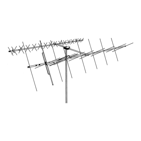
Hy-Gain AV-18VS User manual

Hy-Gain

Hy-Gain AV-18VS User manual

Popular Antenna manuals by other brands

Ubiquiti RocketDish RD-5G30 quick start guide

Ubiquiti

Ubiquiti RocketDish RD-5G30 quick start guide

Yageo Pulse LARSEN LM Series quick start guide

Yageo

Yageo Pulse LARSEN LM Series quick start guide

DX Engineering RF-PRO-1B manual

DX Engineering

DX Engineering RF-PRO-1B manual

ETS-Lindgren 3106B user manual

ETS-Lindgren

ETS-Lindgren 3106B user manual

DX Engineering DXE-60VE-1P user manual

DX Engineering

DX Engineering DXE-60VE-1P user manual

Winegard Trav'ler SK-3005 Setup

Winegard

Winegard Trav'ler SK-3005 Setup

MotoSAT DataStorm G74 Brochure & specs

MotoSAT

MotoSAT DataStorm G74 Brochure & specs

MELICONI AT55 R1 USB WHITE Instructions for use

MELICONI

MELICONI AT55 R1 USB WHITE Instructions for use

Gotting HG G-98810-C Technical description

Gotting

Gotting HG G-98810-C Technical description

RCA ANT500 Specifications

RCA

RCA ANT500 Specifications

Shakespeare Electronic 476 manual

Shakespeare Electronic

Shakespeare Electronic 476 manual

Televes 149481 Assembly and mounting manual

Televes

Televes 149481 Assembly and mounting manual

Wilson Electronics 301119 installation guide

Wilson Electronics

Wilson Electronics 301119 installation guide

RF Elements UltraDish UD-TP-21 manual

RF Elements

RF Elements UltraDish UD-TP-21 manual

PCTEL GPS-TMG-HR-26N installation instructions

PCTEL

PCTEL GPS-TMG-HR-26N installation instructions

Mohu SKY HDTV instruction manual

Mohu

Mohu SKY HDTV instruction manual

Zonet ZWA3006 Quick installation guide

Zonet

Zonet ZWA3006 Quick installation guide

L3 Narda ADFA Handling and Safety Instructions

L3

L3 Narda ADFA Handling and Safety Instructions

manuals.online logo
manuals.online logoBrands
  • About & Mission
  • Contact us
  • Privacy Policy
  • Terms and Conditions

Copyright 2025 Manuals.Online. All Rights Reserved.