Tubes may be checked in a do-it-yourself tube tester in a
.heighborhood store, or may be taken to a·service shop for
testing. Replace any weak or defective tubes with new
ones of identical type. Before replacing tubes in the
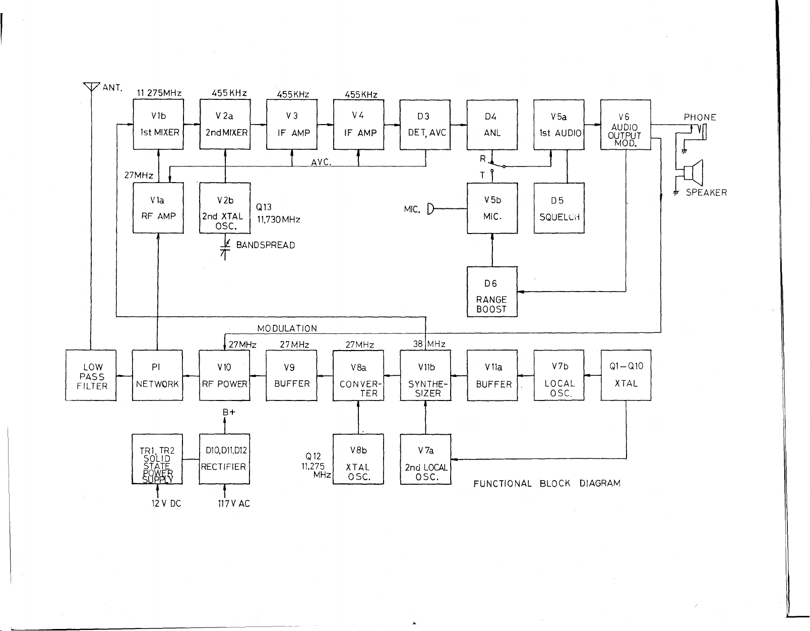
transceiver, refer to the diagram (on
"I
following page)
which shows the correct tube location.
This transceiver employs a solid-state (2-transistor) power
supply circuit during 12 volts DC operation (no vibrator is
used). The transistors, which are located on the rear
panel, have been treated with a Iight protective coating to
avoid possible oxidation. Under no circumstances should
the transistors be allowed to come into contact with the
vehicle chassis, metal brackets, etc. This will cause a
short-ci rcuit and may destroy the trans istors.
There are two pilot lamps used in the transceiver. One of
these is built into the meter, and the other provides illu-
mination for the channel dial plate. Both are run consider-
ably below their maximum rating and should therefore last
almost indefinitely.
The 12-volt DC power cable uses an "in-line" fuse. The
value of this fuse is 8 amp. Provision has also been made
for fusing the primary circuit during 117 volt AC operation
by means of a 2 amp fuse located within the transceiver
(remove bottom cover for access to the fuse).
In the event of complete fai lure (tube filaments and pi lot
lamps not lighting), the fuse should always be checked
first. If it has failed, replace only with one of a similar
rating. Repeated failure of a fuse would indicate a serious
fault in the transceiver which should be investigated.
Connect the transceiver to a power source and attach the
microphone. Turn volume to its mid-pasition squelch at
minimum and the PA switch in the CB position. Set FINE
TUNING to the mid-position (normal) and the CHANNEL
selector to channel 13.
Connect an AC voltmeter (VTVM) across the speaker ter-
minals in the transceiver. Alternatively, the meter can
be connected to the '~Phone" jack by means of a standard
phone plug.
Connect a 455 KHz signal generator (modulated 30% at
1 KHz) to pin 2: of V2 (6BL8). Make certain the output
frequency of the generator is within 1 KHz of 455 KHz.
Increase generator output unti I the VTVM reads approxi-
mately 0.5 volts.
Adjust the top and bottom tuning cores of T3, T4 and T5
for maximum output. Reduce generator output progressively
as circuits come into line so that VTVM reading does not
exceed about 0.5 volts. When no further increase can be
obtained by adjusting the cores, disconnect the signal
generator and proceed with the 11.275 MHz IF adjustments.
Connect the signal generator to pin 9 of V1 (6BL8), with
the VTVM connected to ·the speaker termi naIs. Make sure
the Fine Tuning control is in the normal, center position.
Tune the generator in the vicinity of 11.275 MHz until a
maximum reading is obtained on the VTVM. Reduce gener-
ator output level unti I the meter reads about 0.5 vol ts.
Adjust top and bottom cores of T2 for maximum reading,
reducing generator output if necessary so that reading
does not exceed 0.5 volts.
The second socilIator V2B (6BL8) is crysta I-controll ed.
The Fine Tuning control permits fine tuning of the receiver
and has a total range of about 2.5 KHz. A normally func-
tioning oscillator will develop approximately -1.5 to -8
volts at pin 9 of V2B. Differences in individual crystal
activity will cause a variation in grid voltage for crystal
to crystal.
The master local oscillator, V7B, is crystal-controlled and
is used during both transmit and receive. A normally
function ing osci IIator wi II develop approxi mately -4.5
volts at pin 9 of V7B (see voltage chart). Differences in
individual crystal activity wi II cause a variation in the
voltage measured at this point.
A local oscillator is tuned as follows: adjust the bottom
core of L7 for maximum negative reading at pin 9 of V7B
with the channel selector 'SWitch set to channel 23, then
back off from peak in a clockwise direct-ion to about 70%
of the maximum reading. Check all channels for activity.
A defective crystal will produce zero voltage at pin 9 in
four consecutive channels.
After this adjustment has been made, check transmitter
output frequency to make sure it is within FCC specifica-
tion on all channels. Readjust L7 if necessary.
The synthesizer (V11B) is used during both transmit and
receive. A normally functioning oscillator will develop
approximately -0.3 volts at V7A pin 2 (see voltage chart),