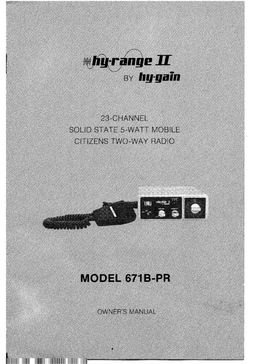
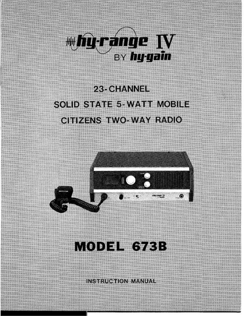
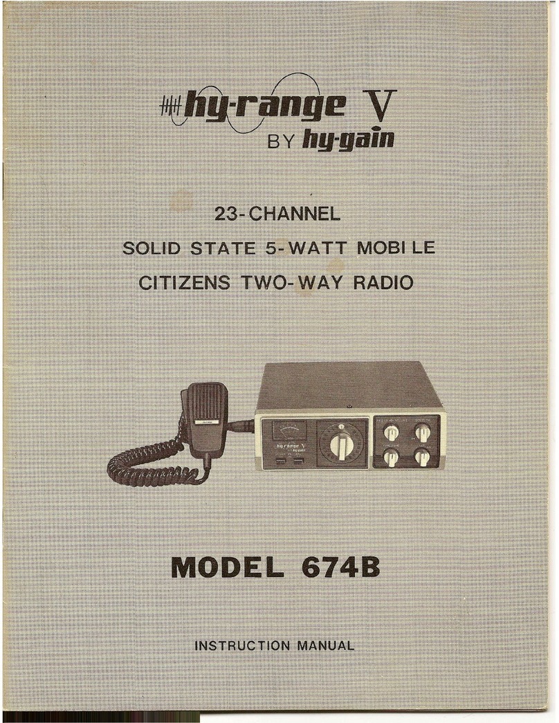
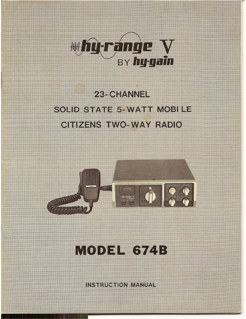
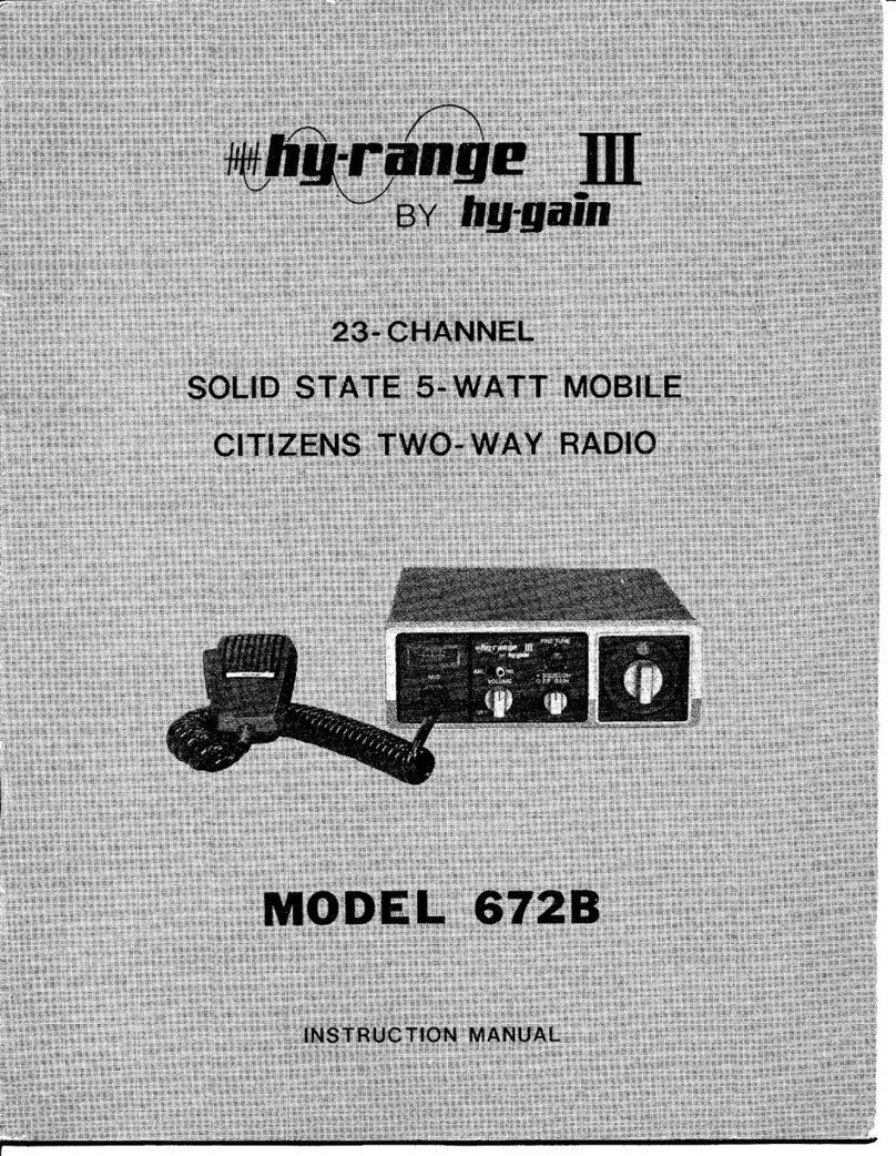
Hy-Gain 670B Hy-Range I User manual


Your Hy-Range I is a 23-channel transceiver designed and licensed for
Class D Citizen Band operation as designated by the Federal Com-
munications Commission (F.C.C.).
The Hy-Range I is a compact completely solid state unit providing
high reliability and low power consumption. This transceiver utilizes
a highly advanced, unique system of frequency synthesization enabling
immediate operation on all 23 channels without the need of additional
crystals or adjustments. Additional features include a jack for con-
nection of an optional telephone handset.
The Hy-Range I transceiver is designed to operate from 11.5 to 14.5
volts DC. To obtain the best results from your transceiver, it is
suggested that you read all the instructions contained in this manual.

PUSHTO~TALI MICROPHONE
POWER CORDS
(DC 12V) FUSE
HOLDER
I
REMOTE
SPEAKER
JACK
ANTENNA
CONNECTOR

Sensitivity
IF frequency
Audio output .
Receiving current drain ..
CB Transmitter Section
Frequency.
Power input
RF Power output.
Emission .
Transmitting current drain
An~nna .
dual conversion superheterodyne with
RF stage and 455 kHz ceram ic filter
23 crystal-controlled channels in the
27 MHz Citizens Band
0.7/lV for 10 dB (S
+
N) N ratio
1st IF: 11.275 MHz
2nd IF: 455 kHz
3 watts maximum
about 100 mA on Standby (no signal)
23 crystal-controlled channels on 27
MHz Citizens Band.
5 watts
4 watts
. all harmonic and spurious suppres-
sion better than Federal Communi-
cations Commission and Depart-
ment of Communications (DOC)
requirements
yields high average modulation at
average voice levels.
less than 1.0 amp @12 VDC nominal
nominal 50 ohms impedance

Licensing your Citizens
Two-way Radio in the
United States
NOTICE: It is illegal to transmit with this transceiver until you
obtain your citizens two-way radio Class D license. You are also
required to read and understand Part 95 of the Federal Communi-
cations Commission rules and regulations before operation of this
unit, License application Form 505 is packed with your transceiver
and Part 95 of the regulations may be available from your dealer;
if not, you may obtain copies from the Superintendent of Documents,
Government Printing Office, Washington, D.C. 20402.
It is also prohibited by the F.C.C. to adjust the transmitter circuit of
this unit unless you hold a current First or Second Class Radio-
telephone License.
We recommend that you refer all servicing of any Hy-Gain products to
your nearest Hy-Gain warranty service center or consult your Hy-
Gain dealer or distributor for the service center location nearest you.
Do not tamper with any internal adjustments or settings - - such
tampering can adversely affect the performance of your transceiver
or may, in fact, cause your unit to operate beyond the limitations
set forth for Class D citizens two-way transceivers by the F.C.C.
General Considerations
Before installing the transceiver in a car, truck, boat, etc., be sure to
choose a location which is convenient to the operating controls and
will not interfere with the normal functions of the driver. The
transceiver may be mounted to the underside of the instrument panel
or dashboard of a car, truck, boat, etc., by means of the special
bracket supplied with your transceiver.
Mounting Bracket
Attach the bracket to the underside of the instrument panel using
four or more screws (see Figure 3). Secure the transceiver to the
bracket by means of the large thumb screws
DC Power Connections
The Hy-Range I may be operated from a nominal 12 volts DC battery
source on negative or positive ground systems.
f\JOTE: Before making any power connections, determine whether
the vehicle has a negative or positive ground electrical system, then
make the following connections:
Connect the red lead to the vehicle
u- -u
(positive) side of the electrical
system, and the black lead to the vehicle (negative) side of the
electrical system.
In the case of negative ground vehicles. the red lead should be
connected to the accessory post on the ignition switch, the voltage
regu lator side of the ammeter or the accessory side of the fuse block.
The black lead should be connected to the metal firewall or any other
point that is connected to the vehicle chassis (ground).

In the case of positive ground vehicles, the black lead should be
connected to the accessory post on the ignition switch, the voltage
regulator side of the ammeter or the accessory side of the fuse block.
The red lead should be connected to the metal firewall or any other
point that is connected to the vehicle chassis (ground).
Antenna Connection
The antenna should be connected to the transceiver by means of
coaxial cable. Either RG-58/u or RG-8/u coaxial cable may be used.
The cable should be terminated with a PL-259 coaxial connector.
Screw the PL-259 coaxial connector onto the antenna jack.
Caution
Do not try to transm it without an antenna connected to the trans-
ceiver.
External Speaker (EXT. SP.) Jack
This jack can be used with any 8-ohm earphone or speaker. Inserting
a 3.5 mm plug into the jack automatically silences the internal speaker.
Remote Speaker Jack
This will be used to control the built-in speaker when operating the
transceiver with the optional telephone handset connected.

Tune-up
In most mobile installations, ignition noise is a problem.
Before beginning any special noise suppression steps, be sure that the
vehicle is well-tuned. Clean and tighten all electrical connections,
including alternator, battery, regulator and coil connections. Perform
the following maintenance steps as necessary. Solder any crimped
spark plug or distributor leads; clean and regap or replace spark
plugs and ignition points; and check and clean alternator rings or
generator brushes. Retune the engine at the manufacturer's recom-
mended intervals.
Corrective Steps
Usually several sources of noise are present in any vehicle, with the
strongest covering the others. In order to find and eliminate the
maximum number of noise sources, you will have to start with the
strong sources and then work back. To be sure the noise you hear
comes from your vehicle and not outside it, drive to a relatively
quiet location (free of man-made electrical interference such as noisy
power lines, industrial noise or other vehicles). Test for noise with
a weak signal on the channel and the engine off. Then start the
engine. Ignition noise will probably be present at all engine speeds.
If it is severe, it may make a normally readable signal unreadable.
To reduce ignition noise, install resistor-type spark plugs if these
are not already installed. If non-resistance ignition wiring is used,
install a 10k-ohm suppressor resistor at each spark plug tower of
the distributor. Install a coaxial capacitor at the ignition coil primary
as close to the coil primary as possible. This capacitor can be purchased
from an electronics parts company or an automotive electrical service
company.
A "whining" noise which varies with engine speed and continues
with the ignition turned off and the vehicle coasting in gear is char-
acteristic of the alternator. Check and clean it and install an alternator
filter (same sources as above).
An irregular, clicking sound which disappears at a slow idle charac-
terizes the voltage regulator. Install a 4-ohm carbon resistor as close
to the field terminal of the regulator as possible, then a .002
11
F
capacitor in series with and as close to the resistor as possible. Con-
nect the capacitor to ground. See the detail drawings of Figure 4.
Irregular popping noises which vary with road surfaces indicate
static discharge at any of several locations in the vehicle. Tighten
loose nuts and bolts and bond large areas such as the fenders, exhaust
pipe, firewall, etc. to the frame with lengths of heavy wire braid.
More Help
Figure 4 illustrates these noise suppression steps. Additional infor-
mation is available in the Radio Amateur's Handbook published by
the
ARRL

1-1
O.1,uF COAXIAL
rT7
1-
~--------~nr~
iIi
ALT:
~i
li1i
~ I
Iii
/-h
LLJJ'
rfl-
or
I
I
GENERATOR
1m
i: __
~HII
~~
I
TO
I
ACCESSORIES
i
i
~
i
BALLAST
RESISTOR
O.1,uF COAXI:~
~
i
~~~~S:O:~~6~E
SPARK PLUG BREAKER
c--~---
ru,~,
~r
~ CC G
[ NNER FENDER WALL
SELF-TAPPING SCREW
and LOCK WASHER
(typical)
SELF- TAPPING SCREW
and LOCK WASHER
(typical)

Power/Volume switch.
To turn the power on, rotate the knob clockwise. further rotation
will increase the sound output from the speaker. To turn the power
off, rotate the knob counterclockwise until the click is heard indicating
the power is turned off from the power supply.
Squelch Control.
This control is used to eliminate annoying background noise at no
signal. To adjust the squelch control properly, first turn the knob
counterclockwise until background noise is heard. Then, rotate the
knob slowly clockwise until the background noise just disappears.
At this point, the receiver will be relatively quiet under no signal
conditions, but an incoming signal will overcome the squelch action
and be heard. Since this control is variable, it can be used to provide
varying degrees of sensitivity to incoming signals. As the control is
advanced from the extreme counterclockwise position the squelch
action is progressively increased and stronger signals are needed to
overcome it. To receive extremely weak signals or to disable the
squelch circuit, simply turn the control fully counterclockwise.
Channel Selector.
Continuously rotating switch selects anyone of 23 channels for
transmit and receive operation.
Mic Jack.
Connect the push-to-talk microphone or the optional telephone
handset.
SignaI Strength/R F Power Meter.
During reception, the built-in meter provides a relative indication of
signal strength in "S" units on the upper scale and offers comparison
between one incoming signal and another.
During transmit, this will provide an indication of antenna RF power
on the lower scale. As you speak, the pointer shou Id "flicker"
slightly, indicating that you are modu lating the RF carrier.
CB Transmitter Operation
IMPORTANT: Do not try to transmit without a citizens two-way
antenna connected to the antenna connector on the rear panel.
1. Turn the power on.
2. Turn channel selector to a desired channel.
3. Depress the push-to-talk button on the microphone. Hold the
microphone 4 to 6 inches from the mouth. Speak at a normal
level. During periods of transmission, the receiver is silenced
and reception is therefore impossible. In the same way, your
signal can not be heard by another station when he is transmitting
each must take turns.
4. To receive, simply release the microphone push-to-talk button.

~~ I
, I
~
i
G'i'l
I
I

If your receiver should need servicing under the warranty, contact
your Hy-Gain dealer for the Hy-Gain Service Center nearest you.
Please contact the Service Center before shipping your transceiver
to him. All equipment returned for warranty repair must be ac-
companied by your sales slip or invoice, or a copy of either.
Units that have been modified cannot be accepted for repair.
Include all information requested by the Service Center. Then pack
the unit as follows:
Check the unit to see that all parts and screws are in place. Then wrap
it in heavy paper or put it in a plastic bag. If the original carton
is not available, place the unit in a strong carton that is at least six
inches bigger in all three dimensions than the unit. Fill the carton
equally around the unit with resilient packing material (shredded
paper, excelsior, etc.). Seal it with gummed paper tape, tie it with
a strong cord, and ship it by prepaid express, United Parcel Service,
or insured parcel post to the Hy-Gain Service Center.
It is very important that the shipment be well-packed and fully
insured. Damage claims must be settled between you and the carrier
and this can delay repair and return of the unit to you.
Parts can be purchased from the factory Customer Service Depart-
ment. All parts orders must be prepaid or COD. When ordering,
please supply the following information:
1. model number of the unit
2. serial nu mber of the un it
3. description of the part
4. part nu mber.
Hy-Gain Warranty
Service Department
4900 Superior Avenue
Lincoln, Nebraska 68505
Attn: National Service Manager

Hy-Gain Electronics Corporation warrants all products manufactured by it and bearing Hy-Gain model
numbers to be free from defective material and workmanship under normal use and service and
agrees to repair such products. If investigation discloses the defect to be the fault of our manufacture.
Hy-Gain's obligation under this warranty is limited to repairing any such product which, upon our
examination, proves to be so defective. All products repaired under such warranty must be returned
to the Hy-Gain factory, transportation prepaid by the purchaser, within ninety days from the date
of purchase .. 9
This warranty applies only to the original purchser. Upon receipt of equipment, the buyer is
responsible for checking the contents for damage. Any shipping damage should be referred to the
carrier.
This warranty does not apply to any Hy-Gain products which have been repaired, worked on, or
altered by persons not authorized by Hy-Gain to do so, or products to which the repair has injured
the stability or reliability of such product, or which has been the subject of mis-use, negligence, or
accident, or the serial number of which has been removed, altered, effaced, or in any other way
rendered unidentifiable. Neither does this warranty apply to any of our products which have been
connected, installed, used, or otherwise adjusted other than in accordance with instructions furnished
by Hy-Gain. Nor does Hy-Gain Electronics Corporation assume any liability for consequential
damages, and in any event, our liability shall in no case exceed the original purchase price of the
product.
Accessories supplied by, but not manufactured by Hy-Gain Electronics Corporation, shall carry only
such warranty as is available from the manufacturer of such goods and are specifically excluded from
Hy-Gai n warranties.
This warranty is void if Hy-Gain shall inspect equipment and find that it has been modified, or
improperly installed or used. This warranty is expressly in lieu of all other warranties. Expressed
or implied, and all other obligations or liabilities on the part of Hy-Gain. No person, including any
dealer, agent, distributor, or representative of Hy-Gain is authorized to assume for Hy-Gain any
liability on its behalf, or in its name, except to rerer purchasers to this warranty.
Warranty Service Department
Hy-Gain Electronics Corporation
4900 Superior Avenue
Lincoln, Nebraska 68505
You must mail the warranty card in immediately. Then, in making a claim, you need only furnish the
model and serial numbers of the unit. However, if for some reason the card was not mailed, a copy
of a document, such as a sales receipt, recording the date, place, and proof of purchase may, at the
discretion of the service department, serve to establish your warranty. Your warranty claim letter
should include all pertinent details, along with the part or item numbers involved. Do not return
anything until requested to do so. You must supply the above information.
Any returned items must have prior authorization. Unexpected returns are greatly delayed in
handling. These delays can be avoided by writing in advance, furnishing the necessary information.
Hy-Gain reserves the right to make changes in design and improvements on its products without
assuming any obligation to install the same on any of its previously manufactured products. Further,
Hy-Gain reserves the right to ship new and/or improved products which are similar to the form, fit,
and function of products originally ordered.

~D
DE PUERTO RICO
Table of contents
Other Hy-Gain Two-way Radio manuals

Hy-Gain
Hy-Gain Hy-Range III 672B User manual

Hy-Gain
Hy-Gain Hy-Range IV 673B User manual

Hy-Gain
Hy-Gain 2795 User manual

Hy-Gain
Hy-Gain hy-range User manual

Hy-Gain
Hy-Gain Hy-Range V 674B User manual

Hy-Gain
Hy-Gain 2795 User manual

Hy-Gain
Hy-Gain hy-range II 671B-PR User manual

Hy-Gain
Hy-Gain 673B User manual