HYDAC International FSK 127 Series User manual

Rehgrabenstraße 3
D-66125 Saarbrücken-Dudweiler
Phone:
++49 (0)6897-509-901
Fax:
++49 (0)6897-509-909
Internet: www.hydac.com
HYDAC
Accessories GmbH
Bedienungsanleitung
Operating Manual
Manuel d’utilisation
Flüssigkeits-
Standkontrolle FSK
Fluid Level
Sensor FSK
Contrôleur
de niveau FSK

2
D
1. Allgemein
Zum ordnungsgemäßen Einsatz dieser
Flüssigkeitsstandkontrolle ist die folgende
Betriebsanleitung zwingend zu beachten.
2. Funktion
H DAC Flüssigkeitsstandkontrollen
überwachen das Füllstandsniveau in einem
Hydraulikbehälter. Die Unterschreitung eines
Minimalniveaus wird dabei über ein
elektrisches Schaltsignal übermittelt.
Das Schaltsignal ( max. Schaltstrom 0,2 A )
kann als Warnmeldung zur
Niveauregulierung eingehen oder direkt in
einer SPS - Steuerung Verwendung finden.
Bei der Öffner - Variante wird der Stromkreis
bei erreichen des minimalen Füllstands
geöffnet, in der Schließer - Variante
geschlossen und bei der Wechsler - Variante
können beide Schaltfunktionen zur
Steuerung bzw. Anzeige verwendet werden.
Eine Optische Anzeige des Füllstandes ist
bei allen Ausführungen zusätzlich
gewährleistet.
Behälter-Füllstand
Behälter-Füllstand
Öffner
Schließer

3
D
3. Kenngrößen
3.1 BENENNUNG & S MBOL
3.2 BAUART
Die Geräte sind zum direkten Anbau an
einen Druckflüssigkeitsbehälter konzipiert.
3.3 BEFESTIGUNGSART
Behälterseitig Gewindebohrung M12 oder
M10
alternativ Durchgangsbohrung Ø 13 oder
Ø 11
3.4 EINBAULAGE
Senkrecht an der Behälterwand
(Anschlußstecker zum Behälterboden)
3.5 MASSE
FSK 127 - 0,21 kg
FSK 176 - 0,23 kg
FSK 254 - 0,26 kg
FSK 381 - 0,30 kg
O-Öffner
C-Schliesser
W-Wechsler

4
D
3.6 UMGEBUNGSTEMPERATURBEREICH
min. 20°C
max. +80°C
3.7 WERKSTOFFE
Anschlußstücke und Steigrohr:
hochwertiger Kunststoff
Gehäuserahmen: Aluminium
Dichtungen: Viton (FKM)
Schrauben und Muttern: Stahl verzinkt
3.8 H DRAULISCHE KENNGRÖSSEN
3.8.1 Nenndruck
PN 0,5 bar
3.8.2 Druckflüssigkeit
Mineralöl nach DIN 51524 Teil 1 und 2
Wasser-Öl-Emulsionen und synthetische
Flüssigkeiten, wie Hydraulikflüssigkeiten auf
Phosphat-Esterbasis
Andere Medien auf Anfrage
3.8.3 Druckflüssigkeits-Temperaturbereich
min. 20°C
max. +80°C
3.8.4 Viskositätsbereich
max. 2000 mm²/s
3.9 ELEKTRISCHE KENNGRÖSSEN
3.9.1 Kontaktbelastung
max. 8 W
3.9.2 Schaltspannung
50 V AC/DC
3.9.3 Schaltstrom
max. 0,2 A
3.9.4 Schutzart
IP 65
Achtung
Achtung

5
D
4. Betriebsbedingungen
4.1 ALLGEMEIN
Für eine einwandfreie Funktion darf der
Einsatzbereich und die Umgebungs-
temperatur nicht überschritten werden
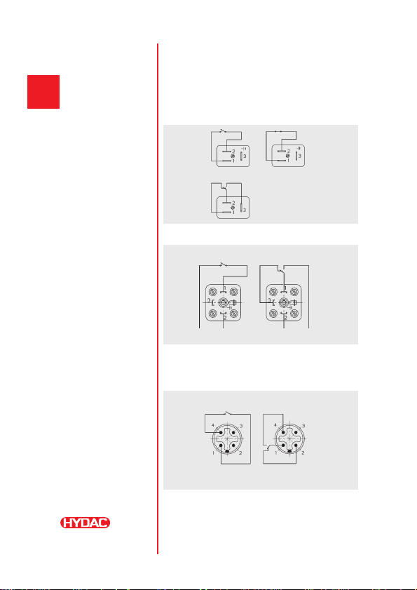
bei falscher Anschlußbelegung ist die
Funktion des FSK nicht gewährleistet.
die elektrischen Anschlußwerte müssen
eingehalten werden.
das angegebene Anzugsdrehmoment der
Hohlschraube von 8 - 10 Nm ist zu
beachten.
zur Montage nur geeignete Werkzeuge
verwenden
nicht für den Einsatz von Glykol bzw.
glykolhaltigen Flüssigkeiten geeignet.
Sonderlösungen mit Glasrohr ( SO 14 ) sind
auf Anfrage lieferbar.
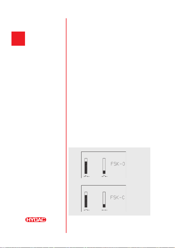
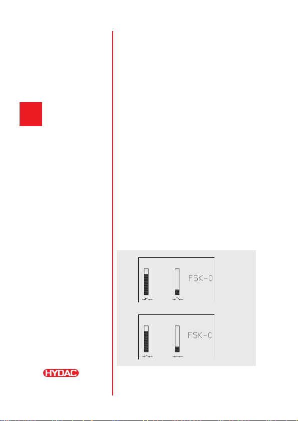
Kennzeichnung der Ausführung am Bauteil
(Rückseite ) O, C, W für verschiedene
Schaltfunktionen
Kontaktschutzmaßnahmen bei kapazitiver
und induktiver Last, bei langen Leitungen
sowie beim Schalten von Glühlampen
können Stromspitzen oder Rückspannungen
zur Kontaktüberlastung führen.
Wir empfehlen dazu geeignete
Schutzbeschaltungen vorzunehmen.
Das Anzeigerohr der FSK darf nicht
unmittelbar mit Reinigungs- oder
Lösungsmitteln in Berührung gebracht
werden, welche zur Behälter- und
Tankreinigung eingesetzt werden. Eine
Beschädigung / Vorschädigung des
Anzeigerohres kann zum Ausfall der
Flüssigkeitskontrolle führen.
Achtung
Gefahr

6
D
4.2 GERÄTEABMESSUNGEN
SW17
Anzugsdrehmoment 8-10 Nm
SW17
Anzugsdrehmoment 8-10 Nm
Baugröße

7
D
4.3 T PISIERUNG
FSK - 127 - 2. X/O/-/ 12
Baugröße :
127, 176, 254, 381
Dich ung : 2 = Vi on (FKM)
Schal kon ak :
O = Öffner
C = Schließer
W = Wechsler
Gewinde der Hohlschraube M12 oder M10

8
D
5. Anschlußbelegung
Hinweis: Im Anlieferungszustand durch
Magnetfeld betätigt (leerer Behälter)
5.1 FSK - STANDARD (MPM - Stecker)
5.2 FSK - Z4 (Hirschmann Stecker)
Hinweis: Schließerfunktion kann mit
Wechsler-Ausführung realisiert werden.
5.3 FSK - SEW (Sensorik Stecker)
Hinweis:Schließerfunktion kann mit
Wechsler-Ausführung realisiert werden
Typ O/Öffner
bei leerem
Behälter
(Auslieferungs-
zustand)
Typ C/S hließer
bei leerem
Behälter
(Auslieferungs-
zustand)
Typ W/We hsler
SO70 Sonderreglung
bei leerem Behälter
(Auslieferungszustand)
Typ O/Öffner
bei leerem
Behälter
(Auslieferungs-
zustand)
Typ W/We hsler
bei leerem
Behälter
(Auslieferungs-
zustand)
Typ O/Öffner
bei leerem
Behälter
(Auslieferungs-
zustand)
Typ W/We hsler
bei leerem
Behälter
(Auslieferungs-
zustand)

9
D
6. ANM RKUNG
Die Angaben in dieser Bedienungsanleitung
beziehen sich auf die beschriebenen
Betriebsbedingungen und Einsatzfälle.
Bei abweichenden Einsatzfällen und/oder
Betriebsbedingungen wenden Sie sich bitte
an die entsprechende Fachabteilung.
Technische Änderungen sind vorbehalten.

10
E
1. General
The following instructions must be followed
in full to ensure correct use of this fluid level
sensor.
2. Function
H DAC fluid level sensors monitor the fluid
level in a hydraulic tank. If the level falls
below a minimum this is transmitted
immediately via an electrical switching
signal. The switching signal (max. switching
current 0.2 A) can be used as a warning
message to regulate the fluid level or directly
to a PLC control. On the FSK type O, the
contact opens when the fluid reaches the
minimum level, on the FSK type C, the
contact closes when the fluid reaches the
minimum level, and on FSK type W (dual
switching circuit), both switching functions
can be used for control or indication.
Visual indication of the fluid level is also
guaranteed on all models.
Tank fluid level
Tank fluid level
opens on
contact
closes on
contact

11
E
3. Technical specifications
3.1 DESIGNATION & S MBOL
3.2 T PE OF CONSTRUCTION
The units are designed to be mounted
directly on to the fluid tank.
3.3 T PE OF MOUNTING
Threaded holes on the tank side M12 or
M10,
alternatively clearance holes Ø 13 or Ø 11.
3.4 MOUNTING POSITION
vertically on the tank wall
(connection plug at the bottom of the tank)
3.5 WEIGHTS
FSK 127 - 0.21 kg
FSK 176 - 0.23 kg
FSK 254 - 0.26 kg
FSK 381 - 0.30 kg
O - N/C contact
(opens when fluid at switching
level)
C - N/O contact
(closes when fluid at switching
level)
W - N/O or N/C contact
(dual switching unit)

12
EE
3.6 AMBIENT TEMPERATURE
min. 20°C
max. +80°C
3.7 MATERIALS
End caps and tube:
High quality synthetic material
Housing: Aluminium
Seals: Viton (FKM)
Bolts and nuts : Steel (zinc-plated)
3.8 H DRAULIC SPECIFICATIONS
3.8.1 Nominal pressure
PN 0.5 bar
3.8.2 Operating fluids
Mineral oil to DIN 51524, part 1 and 2
Water-oil emulsions and synthetic fluids,
such as hydraulic fluids based on
phosphate-ester.
Other fluids on request.
3.8.3 Temperature range of operating fluid
min. 20°C
max. +80°C
3.8.4 Viscosit range
max. 2000 mm²/s
3.9 ELECTRICAL DETAILS
3.9.1 Contact load
max. 8 W
3.9.2 Switching voltage
50 V AC/DC
3.9.3 Switching current
max. 0.2 A
3.9.4 Protection class
IP 65
Warning
Warning

13
E
4. Operating conditions
4.1 GENERAL
For correct operation, the application range
and the ambient temperature must not be
exceeded.
If the connections are incorrect, the function
of the FSK is not guaranteed.
The electrical connection values must be
observed.
The given torque rating for the banjo bolt of
8 - 10 Nm must be observed.
Use only appropriate tools to fit the sensor.
Not suitable for use with glycol or fluids
containing glycol. Special models with a
glass tube (SO 14) are available on request.
The type code is marked on the back of the
sensor: O, C, W for the different switching
functions
Designing the protective network
When using reed switches to switch
inductive or capacitive loads, including long
cables or lamps, a protective network should
be used to ensure the life of the switching
contacts.
The tube of the FSK must not come into
direct contact with cleaning fluids or solvents
which may be used to clean the tank.
Damage to the tube can result in breakdown
of the fluid level sensor.
Danger
Warning

14
E
4.2 DIMENSIONS
SW17
Torque 8-10 Nm
SW17
Torque 8-10 Nm
Size
E

15
4.3 MODEL CODE
FSK - 127 - 2. X/O/-/ 12
Size:
127, 176, 254, 381
Ma erial of seal: 2 = Vi on (FKM)
Swi ching con ac :
O = opens a he swi ching level
C = closes a he swi ching level
W = opens or closes a he swi ching level
Banjo bol hread: M12 or M10
E

16
F
5. Circuit diagrams
No e: Before ins alla ion, swi ch is ac ua ed by magne ic
field (i.e. ank emp y). All circui s below are shown
before ins alla ion (i.e. when ank is emp y).
5.1 FSK - STANDARD (MPM plug)
5.2 FSK - Z4 (Hirschmann plug)
Note:Closing function is possible using the
dual switching unit
5.3 FSK - SEW (Sensor technology plug)
Note: Closing function is possible using the
dual switching unit
E
Type: O -
Opens when
fluid at
swit hing level
Type: C - Closes
when fluid at
swit hing level
Type: W - Dual swit hing unit
(Spe ial ontrol - SO 70)
Type: O -
Opens when
fluid at
swit hing
level
Type: W - Dual
swit hing unit
Type: O -
Opens when
fluid at
swit hing level
Type: W - Dual
swit hing unit

17
6. Note
The information in this brochure relates to
the operating conditions and applications
described.
For applications or operating conditions not
described, please contact the relevant
technical department.
Subject to technical modifications. E

18
FF
1. Généralités
Pour une utilisation conforme de ces
contrôleurs de niveau, il est nécessaire de
respecter expressément la notice suivante.
2. Fonction
Les contrôleurs de niveau H DAC assurent
le contrôle du niveau de remplissage dans
un réservoir hydraulique. Lorsque le fluide
est en dessous du niveau minimal, un signal
de commutation électrique est transmis.
Le signal de commutation (courant de
commutation max. 0,2 A) peut provoquer un
signal d'alarme en vue de la régulation du
niveau ou être directement utilisé pour le
pilotage d'un automate. En version
"ouvrant", le circuit électrique est ouvert
lorsque le niveau de remplissage est atteint,
dans la variante "fermant" il est fermé et
dans la variante "inverseur", les deux
fonctions de commutation peuvent être
utilisées pour le pilotage ou l'affichage.
Un affichage optique du niveau de
remplissage est de plus garanti pour toutes
les exécutions.
Niveau de remplissage
Ouvrant
Fermant

19
F
3. Caractéristiques
3.1 DESIGNATION & S MBOLE
3.2 T PE DE CONSTRUCTION
Les appareils sont conçus pour le montage
direct sur les réservoirs de fluide sous
pression.
3.3 T PE DE FIXATION
Côté réservoir taraudage M12 ou M10
ou trou débouchant Ø 13 ou Ø 11
3.4 SENS DE MONTAGE
Vertical sur la paroi du réservoir
(connecteur dirigé vers le bas)
3.5 MASSE
FSK 127 - 0,21 kg
FSK 176 - 0,23 kg
FSK 254 - 0,26 kg
FSK 381 - 0,30 kg
O-Ouvrant
C-Fermant
W-Inverseur

20
FFF
3.6 PLAGE DE TEMPERATURE AMBIANTE
min. 20°C
max. +80°C
3.7 MATERIAUX
Pièces de raccordement et tube :
matière plastique
Cadre : aluminium
Joints : Viton (FKM)
Vis et écrous : acier zingué
3.8 CARACTERISTIQUES H DRAULIQUES
3.8.1 Pression nominale
PN 0,5 bar
3.8.2 Fluide h draulique
Huile minérale selon DIN 51524 chap. 1 et
2, émulsions eau-huile et fluides
synthétiques, comme les huiles hydrauliques
à base d'ester phosphate.
Autres fluides sur demande
3.8.3 Plage de température du fluide
min. 20°C
max. +80°C
3.8.4 Plage de viscosité
max. 2000 mm²/s
3.9 CARACTERISTIQUES ELECTRIQUES
3.9.1 Puissance de commutation
max. 8 W
3.9.2 Tension de commutation
50 V AC/DC
3.9.3 Courant de commutation
0,2 A
3.9.4 Indice de protection
IP 65
Attention
Attention
This manual suits for next models
3
Table of contents
Languages:
Other HYDAC International Measuring Instrument manuals
Popular Measuring Instrument manuals by other brands

Onicon
Onicon System-10 BTU Meter Installation and operation guide

AFRISO
AFRISO Oxystem 250 operating instructions

Extech Instruments
Extech Instruments SDL350-NIST user manual

CARLO GAVAZZI
CARLO GAVAZZI EM21 - COMMUNICATION PROTOCOL V1 REV0 Communication protocol

Met One Instruments
Met One Instruments 076B Operation manual

Gas Data
Gas Data GFM 436 Technical user's manual