10 English
PROFESSIONAL external lter
Dear Customer,
Thankyou forchoosing this product.Thenew PROFESSIONAL lteroers an extremely
wide range, in which you are sure to nd the model best suited to your needs. The
PROFESSIONAL range of lters will also allow you to use the various ltering materials
available in a professional way, guaranteeing a ltering process specically tailored to
your aquarium. Please read the instructions below carefully, so you can get the best
out of your Professional lter and fully appreciate the features that make it truly one
of a kind.
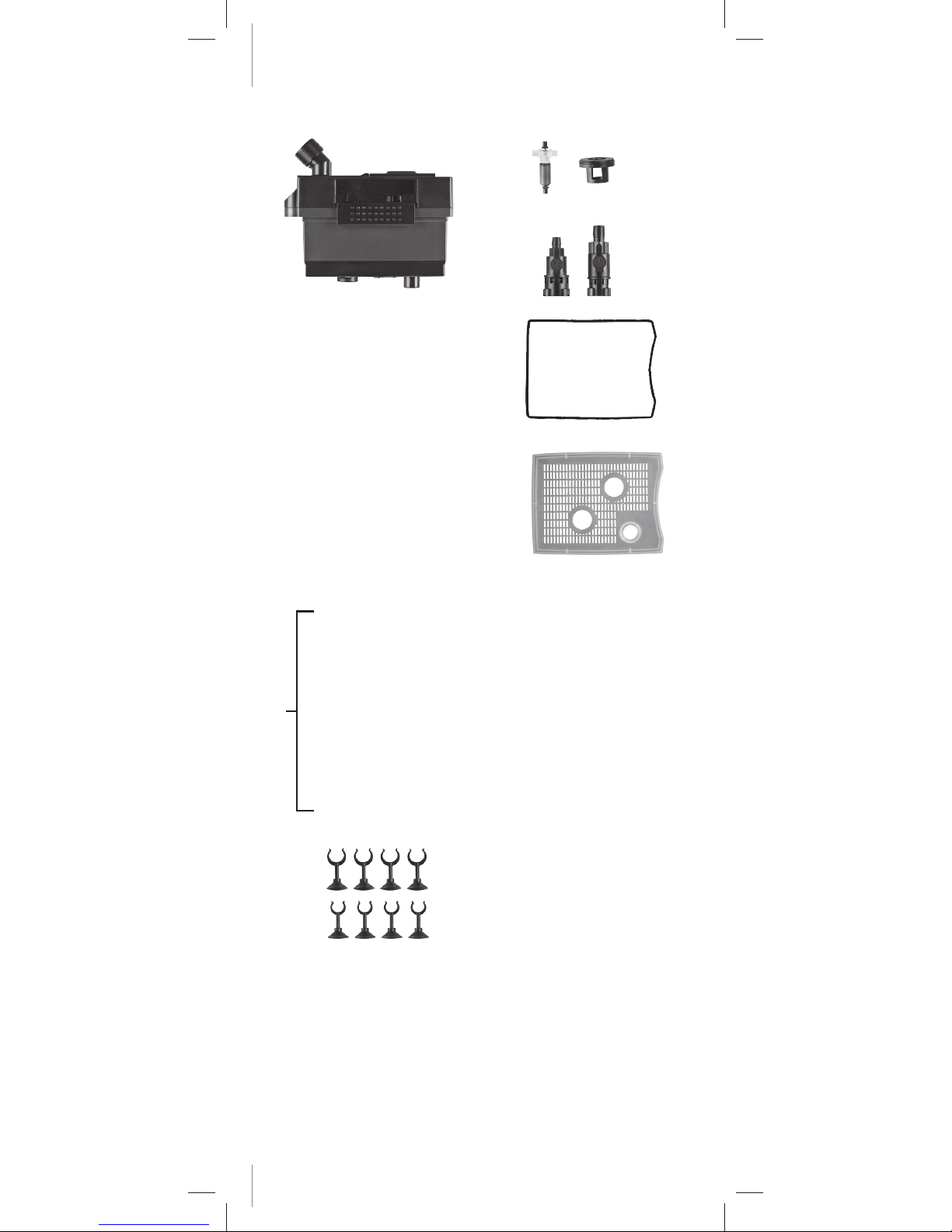
Description
PARTS OFTHE FILTER
1. Body of the lter
2. Head of the motor
3. Magnetic rotor with ceramic shaft
4. Rotating lid
5. IN - OUT taps
6. O-ring motor head
7. Lid of ltering material container
8. Filtering material container
9. U-shaped suction tube
10. U-shaped delivery tube
11. Pre-lter grid
12. Clips with suction cap
13. Flexible tubes
14. Spray bar
Installation
N.B.: before carrying out any work or maintenance on your aquarium, disconnect all electrical
appliances installed inside or outside of it. Check that the voltage indicated on the product
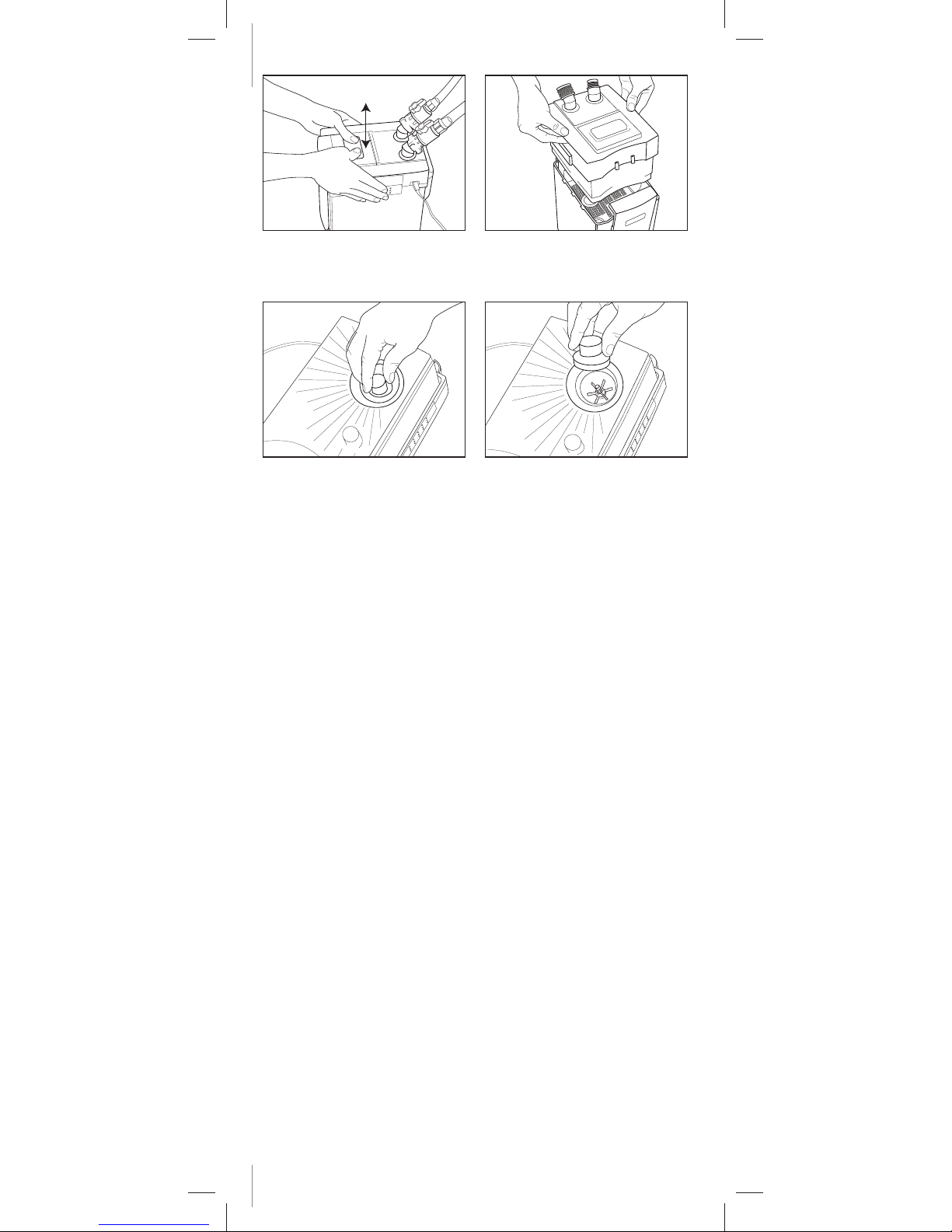
corresponds to that of your power supply network. The Professional lter should be below the
level of the aquarium when it is primed (g. 1).
If you wish to position it at the side, you must do so only once the lter has begun functioning.
Preparation of the lter
• Placethe lterinthe positionidentied (consider whether this will allowfor easy handling of the
lter during ordinary maintenance operations)
• Connect the U-shaped tubes with their exible tubes, taking care to tighten the ring nuts (g .2).
• Mount the pre-lter grid onto the suction unit.
• Choose the position you consider most appropriate for the suction unit, using the clips with
suction caps (g. 3).
• Assemble the delivery unit and choose a position for it, if possible at a distance from the suction
unit, in order to ensure eective recirculation (g.4).
• If you wish, you may apply the perforated bar to improve oxygenation at a 90° angle (g.4 -5),
positioning it all in the aquarium at the surface of the water (g.6).
• Cut the exible tubes to the length required to ensure the water runs through as straight as
possible, so as to prevent possible (g.7) obstruction of the exible tubes (g. 20).
Initial installation of ltering materials
Forconvenience oftransport, theltering materialsarepositioned insidethe lter.Thelter must
therefore beopened andthe requiredcleaning operations carriedout in orderto prepare thelter
for use. Proceed as follows:
• Rotate the safety levers (g. 8-9) the unblock the pump unit.
• Leavingtheleversintheclosedposition,openthetwoclosinghooksbymovingthemdownwards
and outwards, then raising them and releasing the head (g.10).
• Remove the lid of the ltering materials by inserting your ngers into the appropriate holes to
facilitate the operation (g.11).
• Take out the material containers, in which some ltering materials are still sealed (g.12).
• Open the packs of ltering materials, rinse the materials carefully (g.13-14) and place them in
the containers.The number of containers varies, depending on the model.
• We suggest placing the large-pore sponges (d) at the bottom, the material for biological ltering
(b) in the middle of the lter and the ne-ltering white lter wool (e) at the top (except for
FILTERING MATERIALS
A. Porous cylinders for biological ltering
B. Active carbon for chemical ltering
(optional)
C. Active zeolite for chemical ltering
(optional)
D. Large-pore sponge for mechanical
ltering
E. Filter wool for super-ne mechanical
ltering
F. Large-pore sponge and lter wool in
combination (model 150 only)