Hydra APOLLO Quick guide

APOLLO
AC Dual-Output EV charger with Media Board
ELECTRIC VEHICLE CHARGER
INSTALLATION AND INSTRUCTION MANUAL
APOLLO-V0001-31.03.2022

✆
01268 205 121
| www.hydraev.co.uk | sales@hydraev.co.uk
2
CONTENTS
SAFETY ...................................................................................................................................................................................3
Safety Identication .......................................................................................................................................................3
INTRODUCTION.....................................................................................................................................................................6
Serial Number Identication.........................................................................................................................................6
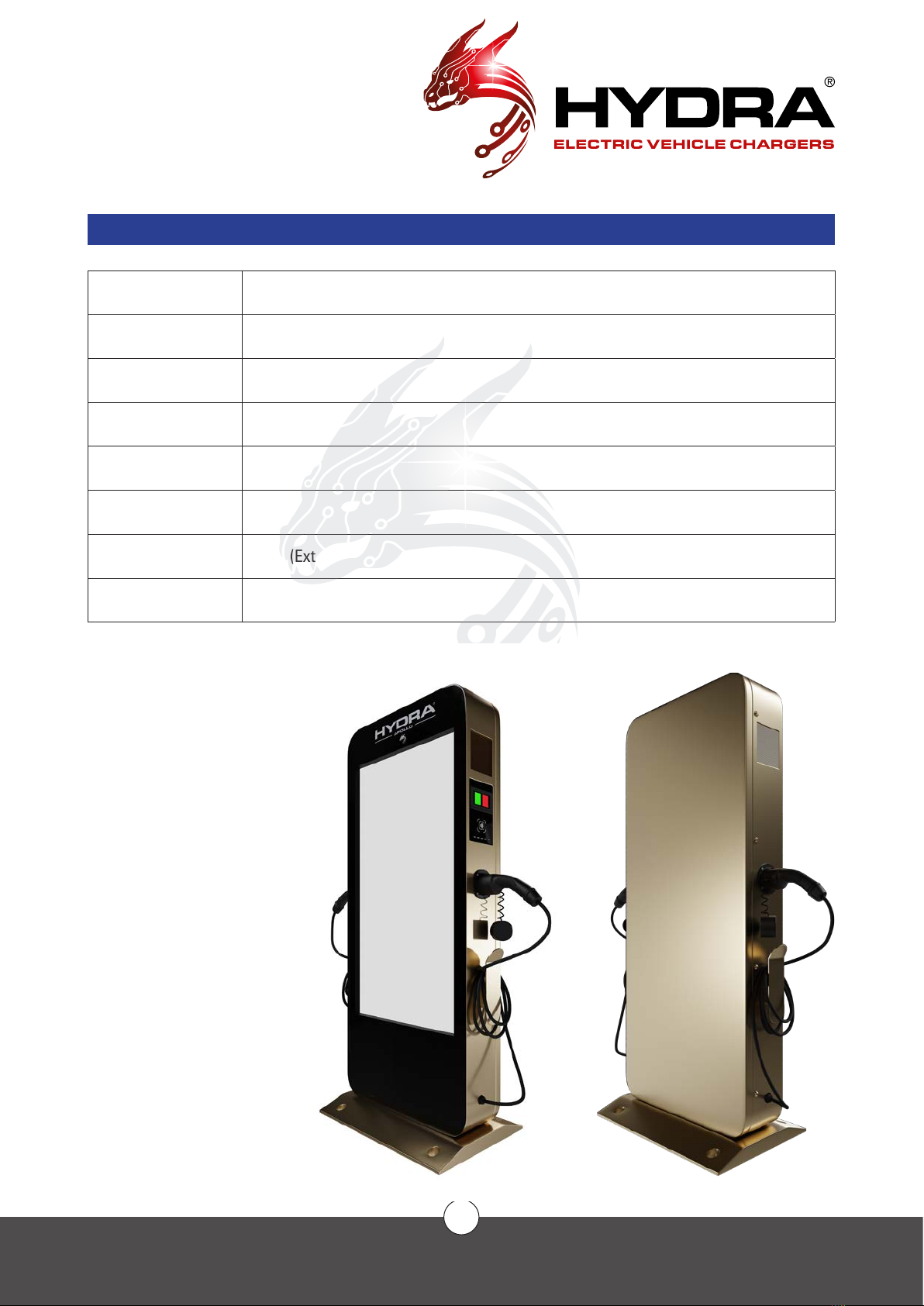
Appearance .....................................................................................................................................................................7
Technical Specications................................................................................................................................................8
Product Features...........................................................................................................................................................10
SYSTEM ARCHITECTURE ..................................................................................................................................................11
Electric............................................................................................................................................................................11
System Communications .............................................................................................................................................11
INSTALLATION ....................................................................................................................................................................12
Procedure.......................................................................................................................................................................12
Network connectivity requirements ..........................................................................................................................13
Tool preparation ............................................................................................................................................................14
Internal structure ..........................................................................................................................................................15
Site Space Requirements ............................................................................................................................................16
Installation Instructions ...............................................................................................................................................17
Electrical Requirements...............................................................................................................................................18
Connect the Power Cable............................................................................................................................................19
COMMISSIONING ..............................................................................................................................................................20
Power on standby owchart.......................................................................................................................................21
Charging Operation.......................................................................................................................................................22
Charging Operation Flowchart....................................................................................................................................22
Non-Operational mode owchart ..............................................................................................................................23
Emergency Operation...................................................................................................................................................24
Setup ...............................................................................................................................................................................25
Ethernet Mode...............................................................................................................................................................26
Using a Static IP address ............................................................................................................................................26
Wi Mode.......................................................................................................................................................................26
WIFI mode ......................................................................................................................................................................27
Set DNS ..........................................................................................................................................................................27
Change the URL.............................................................................................................................................................27
PLATFORM CONECTIVITY .................................................................................................................................................28
Connect to the Chargecore Platform.........................................................................................................................28
AFTERSALES........................................................................................................................................................................29
Aftersales Service ........................................................................................................................................................29
Disclaimer ......................................................................................................................................................................29
Maintenance..................................................................................................................................................................29
Procedures.....................................................................................................................................................................31
During Installation.........................................................................................................................................................31
After Installation............................................................................................................................................................31
APPENDIX............................................................................................................................................................................32
Screen Icon Key............................................................................................................................................................32
Fault Diagnosis ..............................................................................................................................................................33
Electrical Diagram ........................................................................................................................................................34
Restriction of Hazardous substances........................................................................................................................35
Authentication ...............................................................................................................................................................36

✆
01268 205 121
| www.hydraev.co.uk | sales@hydraev.co.uk
3
SAFETY
SAFETY ANNOUNCEMENTS
Before operating the EV charger, read the instructions and precautions carefully to reduce the risk of accidents.
The “caution, warning, hazard” notices in the product and product manual do not represent all safety concerns
to be observed and are only intended to supplement the various operational safety precautions.
In carrying out the company’s product and equipment operations, you must comply with relevant industry safety
norms and strictly abide by these instructions to provide the appropriate equipment precautions and special
safety instructions
IDENTIFICATION DESCRIPTION
Indicates that care must be taken with the operation or condition of hazardous voltage
Important security information must be followed very carefully
Indicates risk of burns from high-temperature areas or areas with high
component temperatures
Ground protected connection point
DC electricity
AC electricity
Indicates that the said action must be performed using clothing and/or personal
protective equipment provided by the employer
Type A Residual Current Devices (RCD)
Type B Residual Current Devices (RCD)

✆
01268 205 121
| www.hydraev.co.uk | sales@hydraev.co.uk
4
SAFETY
ELECTRICAL SAFETY
HIGH VOLTAGE
Some components of the power system operate with high voltage. Direct or indirect
contact with these components through non-insulated protective material poses a fatal
hazard.
The installation of AC power supply equipment must comply with safety regulations, and personnel carrying out
the installation of AC equipment must be qualied in high voltage AC-power operation.
It is strictly prohibited to wear watches, bracelets, rings or other conductive objects on your wrist or hand.
Turn off the power immediately if you nd water or moisture in the electric cabinet. When operating in humid
conditions, water should be strictly prevented from entering the equipment.
A “Do not operate” sign must be hung on switches and buttons that are not to be used during installation.
Construction of high-voltage lines can cause re or electric shock accidents.
The racking and wiring of AC cables through the area must comply with the local
regulations and specications. Only personnel qualied for high-voltage and AC
operations can carry out various high-voltage operations.
TOOLS
Special tools must be used for all high AC voltage operations.
THUNDERSTORMS
High AC voltage operations during thunderstorms are strictly prohibited.
Strong electromagnetic elds are produced in the atmosphere during thunderstorms. To avoid lightning
damage to equipment and personnel, do not carry out any operations during thunderstorms.
ELECTROSTATICS
Static electricity generated by the human body can damage electrostatic-sensitive
components on boards such as large-scale integrated circuits (ICs). To prevent static
damage to sensitive components, personnel must wear an anti-static bracelet when in
contact with equipment (hand-held boards, circuit boards, IC chips, etc.). The anti-
static bracelet must be well-grounded on the other end.

✆
01268 205 121
| www.hydraev.co.uk | sales@hydraev.co.uk
5
SAFETY
SHORT CIRCUITS
It is strictly prohibited to short-circuit the power supply system to the positive and
negative poles or to short the non-ground pole to ground during operation. Short
circuits can cause equipment to burn and pose a personal safety hazard.
In addition, the polarity of the cables and interface terminals must be strictly checked when carrying out live
work.
Power distribution operation space is limited. Before any operation, close attention must be paid to the choice
of operating space.
An insulation tool must be used during operation.
When working with electricity, care must be taken to keep your hands, wrists and arms steady, to prevent
accidents from a tool slipping, or from too much movement of a tool or your body.
SHARP CORNERS
When moving equipment by hand, wear protective gloves to prevent cuts.
POWER CABLE
Make sure that the cable label is correct before connecting the cable.
SIGNAL LINE
The signal cable should be tied separately from the power cable and at
least 15mm away.

✆
01268 205 121
| www.hydraev.co.uk | sales@hydraev.co.uk
6
INTRODUCTION
SERIAL NUMBER DESCRIPTION
PAC 0722 T1T2 A01 No ROU0120030002
1 2 3 4 5 6
6PILE ID NUMBER
ROU01 2003 0002 - ROMANIA CUSTOMER LIST
1,2 MARCH 20, PILE 0002
5 FOUNDRY
4 BOM VERSION
3
STANDARD:
T2: TYPE2 AC
T1: TYPE1 AC
GA: GB/T AC
C2: CCS2
C1: CCS1 J
CHADEMO
GD: GB/T DC
2
CHARGING POWER:
TYPE2 AC PILE RATED POWER 22KW
CCS2 PILE RATED POWER 40KW
CHADEMO PILE RATED POWER 20KW
1
PRODUCT MODEL:
AC001- PLASTIC HOUSING 1 AC PILE
AC002- METAL COLUMN AC PILE
AC003- ALUMINUM AC PILE
AC004- PLASTIC HOUSING 2 AC PILE
AC005- METAL SHELL AC PILE
AC006- POLYCARBONATE REINFORCED ABS AC PILE
PAC- ADVERTISING AC PILE
The HYDRA APOLLO has a single/dual connector output of 7/22/43kw function. Dual outlets can be congured
at the same time or in combination with Type1 J1772, Type2 and Mennekes connectors. The system can be
installed outdoors (but for safety reasons, if the water level reaches the charger connector, it should not be
used in rainy or snowy conditions).

✆
01268 205 121
| www.hydraev.co.uk | sales@hydraev.co.uk
7
INTRODUCTION
APPEARANCE
Use Car Parks / Public Charging Station
Material Metal housing
Dimensions (mm) 600(L)x820(W)x1720(H) excluding hangers, etc
Installation type Free-standing
Cable layout Bottom
Weight 53kg
Cable length ≥4.2m(External Line)
Charging socket Type1 or Type2 or Type1 & Type2
1 Fan (if tted)
2 Touch Screen
3 RFID Card Reader
4 Connector
5 Outlet
6 Media Board (55” screen)
7 Cable holder
➊➊➊➊
➋➋
➌➌
➍➍
➍➍
➏➏
➎➎
➐➐
➐➐

✆
01268 205 121
| www.hydraev.co.uk | sales@hydraev.co.uk
8
INTRODUCTION
TECHNICAL SPECIFICATIONS
COMPONENT
SPECIFICATIONS
Dimensions 600(L) x 820(W) x 1720(H) mm
Weight 185KGS (including cable)
Cable length ≥4.2m
Shell material Alloy
Screen 5” LCD touch screen
POWER
CHARACTERISTICS
Input voltage TN-S 240V AC (single phase)
400V AC (three phase) ±20%
Input frequency 50hz/60hz
Rated power 7kW (single phase)
22kW (three phase)
Measurement accuracy ≤±0.5%
Output voltage Same as input voltage
Output current 7kW/22kW-32A; 43KW-63A
Efciency ≥94%
Factor ≥0.99
DESIGN FEATURES
UI RFID Card Reader, LCD touch screen, Emergency
Stop Button
Standard GB/T, TYPE1 J1772, TYPE2 and IEC61851-1/2017
COMMUNICATION
Web interface Wired Ethernet, Wi-Fi, 3G/4G
OCPP OCPP 1.6J

✆
01268 205 121
| www.hydraev.co.uk | sales@hydraev.co.uk
9
INTRODUCTION
WORKING
ENVIRONMENT
Use Indoor/Outdoor
Operating temperature -20°C ~ +70°C
Operating humidity 5% to 95%
Elevation <2000m
Protection level IP54
Cooling method Ambient air cooling
Ground detection ≤30mA
Sound level ≤50db (normal input/output power at ambient 25°C)
RoHS Meets the R5 requirements of the RoHS directive
TECHNICAL SPECIFICATIONS (CONTINUED)

✆
01268 205 121
| www.hydraev.co.uk | sales@hydraev.co.uk
10
INTRODUCTION
PRODUCT FEATURES
The HYDRA APOLLO AC Charger has a modern design and user-friendly interface, mainly for public
commercial use. The modular design increases charger utilisation and ease of operation and maintenance.
SAFETY FEATURES
Hardware protection features:
Overcurrent protection
Overvoltage protection
Over-temperature protection
Emergency stop protection
Lightning protection
Type B RCD
Comprehensive software protection features, providing multiple protections
Meets IEC61851-22 requirements
All components have CE certicates
The SECC controller has gone through the TÜV test
SMART
The terminal charger is connected to the Open Charge Point Protocol platform online
Remote diagnostics, remote upgrades
Compatible with GB/T, Type1-SAEJ1772, Type 2 and IEC61851-1/2017
Internal high-precision MID AC meter
Supports simultaneous charging of multiple connectors
The OCPP platform sets the maximum output power according to the time period
Support for credit card Point Of Sale payment (optional)
Support for OCPP1.6-J (later direct upgrade to 2.0)
CONVENIENT
Wireless or wired communication, exible networking
Open communication protocol for sweep charge, swipe charging and API services
Several settings to end the charge
Time limit
Amount of electricity
Auto lled
OPTIONAL FEATURES
Plug&Charge (optional)

✆
01268 205 121
| www.hydraev.co.uk | sales@hydraev.co.uk
11
SYSTEM
ARCHITECTURE
ELECTRIC
INTERNAL SYSTEM COMMUNICATIONS
BMS
EVCC
PLC
ISO15118
RS-232
CAN
CHAdeMO/GBT
CP
PP
proprietary
protocol
Internet OCPP
CAN
OCPP
cloud
OCPP
controller
SECC&
EVSE
controller
CANH
CANL
AC
TNS10kV
TN-C-S
10kV/400V
AC
Transformer - Switch - Charger - Car

✆
01268 205 121
| www.hydraev.co.uk | sales@hydraev.co.uk
12
INSTALLATION
PROCEDURE
SAFETY INSTRUCTIONS
The operating voltage and current inside the charging system are high, and the following regulations should be
observed at all times to ensure personal safety:
1.Chargingsystemsmustonly be installed bypersonnelwhohavebeen trained in, andhavesufcientknowledge
of, the charging system. Always follow safety precautions and local safety regulations during installation.
2. To operate inside the charging system, make sure that the charging system is not live. The power input to the
charging system must be disconnected.
3. Distribution cable wiring should be reasonable and protective to avoid accidental contact when operating
power supplies.
VISUAL INSPECTION
Upon product delivery, check that the package is not damaged and that the label is complete and correct. If
there is an issue, immediately inform the carrier and take photos as evidence. At the same time, immediately
contact the manufacturer to discuss the issue.
Only after the goods arrive at the installation site can they be opened and the boxes opened for inspection.
Start by opening the box with the packing slip, taking out the packing list and checking it against each item.
Next, check the serial number of the box, the equipment packaging, the number and type of accessories and
the integrity of all items.
Following the packing list, check that accessories and accompanying documents are complete (refer to the
shipping list) and store the accessories and documents properly.
Carry out a visual inspection to ensure that the product is free of abnormal marks showing collisions, and of
scratches, cracks, dents, rust, breakage, or peeling of paint.
Sign receipt documents, make a record of the situation, keep documents and scan them for archives, or give
them to relevant parties.
ACCESSORY LIST
The packing list comes with the shipping documents.

✆
01268 205 121
| www.hydraev.co.uk | sales@hydraev.co.uk
13
INSTALLATION
NETWORK CONNECTIVITY REQUIREMENTS
The recommended way to connect to the network is to access 4G wireless communication or a Wi-Fi module
integrated in the charger. A SIM card meeting local networking requirements is required. Make sure the local
signal strength is strong and stable; otherwise a signal amplier must be installed.
If there is no local 3G/4G communication signal, a standard wired internet connection is available. Wired
connections must meet the following requirements:
RJ45 Ethernet
Network cable type: 5e class or greater, 8P plus PE, shielding wire.
It is recommended that the line length is less than 75m. Greater than 75m length requires a customised
engineering solution.
Minimum bandwidth required:
Upstream: 128 kbps
Downstream: 4 Mbps
Demand connection reliability: 99.9%.
For special congurations, please contact us.

✆
01268 205 121
| www.hydraev.co.uk | sales@hydraev.co.uk
14
INSTALLATION
NAME DESCRIPTION QTY
Multimeter Checking the electrical connections and electrical parameters 1
Electric impact drill Drilling 1
Impact drill bit (Ø 14mm) Drilling 2
Tape measure (5m) Measurement 1
Level ruler Measurement 1
Crosshead screwdriver Unpacking 1
Pliers Unpacking 1
Wire Stripper Removing the insulation sheath / jacket 1
Terminal pressure line pliers Pressing the terminals 1
Bevel cutting pliers Cutting the cable 1
Light hammer Unpacking, tapping, adjustment 1
Carrying equipment Moving and hoisting charger 1
PVC tape and sheath Insulation tape and insulation cladding connection 1
Personal protection tools Ensuring the health and safety of operators 1
TOOL PREPARATION
STANDARD TOOLS

✆
01268 205 121
| www.hydraev.co.uk | sales@hydraev.co.uk
15
INSTALLATION
INTERNAL STRUCTURE
1 Fans
2 Door
3 PTC
4 Antenna
5 Control Board
6 Temperature Control Board
7 Power Supply
8 Power Supply
9 Power Supply
10 Switch
11 SPD
12 Fans
13 Power Line Outlet
1 Emergency Stop
2 Touch Screen
3 RFID Card Reader
4 LED status indicator
5 OCPP
6 Charge lead output
7 MID relay x 2
8 Auxiliary Power Supply
9 MID Meter x 2
10 Contactor x 2
11 Type B RCD x 2
12 Power in connection
1
3
2
13
1
10
9
87
11
12
2
3
4
5
6
12
11
10
9
8
6
7
5
4

✆
01268 205 121
| www.hydraev.co.uk | sales@hydraev.co.uk
16
INSTALLATION
SITE SPACE REQUIREMENTS
Adequate installation space should be reserved to ensure safe and reliable operation, ventilation and
maintenance of the equipment.
Installation requires 1900 x 1200 mm of space, calculated as follows:
Product size: 900mm(L) X 600mm(W).
Front reserved spacing ≥500mm to ensure the front door open/close operation is normal and all related
operations are unhindered.
Left reserved spacing ≥ 500mm to ensure operating space.
Right-hand reserved spacing ≥ 500mm to ensure operating space.
Rear reserved spacing ≥ 100mm to ensure operating space.
800mm800mm
600mm
300mm
Ø20mm
Ø100mm
900mm900mm
460mm

✆
01268 205 121
| www.hydraev.co.uk | sales@hydraev.co.uk
17
INSTALLATION
FOUNDATION INSTRUCTIONS
A dedicated foundation is not necessary when the equipment is installed indoors or in higher and drier sites,
but the ground level plan error per square meter must not exceed ±1.5mm, and the ground strength level of
the installation position must not be less than C30. When the equipment is installed outdoors and in low-lying,
damp or potentially humid environments, a cement or slot steel base must be installed. The cement base must
be 200mm above the ground (the recommended height below the ground is not less than 500mm). The mounting
surface requires four pre-buried M6 stainless steel bolts, bolt thread exposed to the ground 30±3mm.
The cable wire enters through the bottom of the charger through an inlet hole.
On the ground where the charger is to be installed, dig a hole not smaller than the base dimensions indicated
in the gure below.
Make sure that the cable is accessible from the pre-buried pipe.
Pour the concrete into the concrete foundation shown in the gure below.
It is recommended that the base of the charger be at least 200mm above the ground, effectively reducing the
risk of ooding.
Reserve a cable length of 1m above the base for internal wiring.
Fill the inside and outside of the base with sand and stone. The inlet holes need to be blocked with re-
resistant mud to prevent small animals such as rats from entering the equipment.

✆
01268 205 121
| www.hydraev.co.uk | sales@hydraev.co.uk
18
INSTALLATION
CABINET INSTALLATION INSTRUCTIONS
TRANSFER LOADING AND UNLOADING
Lifting and moving the charger must be carried out by trade professionals using a dedicated load-bearing
forklift/crane or other professional load-bearing transfer device.
Do not drop or hit the device.
Move the equipment to a pre-made concrete base and lift the charger into place with a lifting device.
INSTALLATION:
Carefully and slowly lower the charger into place.
Secure the cabinet to the base.
Make sure that the cable has been passed into the cabinet along the seal sleeve.
Ensure that the cabinet holes and bolts are aligned.
Insert at washers, gaskets and nuts at the four corners and front and rear sides.
Lock these nuts to 95.5 Nm.
Keep the device upright – do not tilt more than ±15 degrees.

✆
01268 205 121
| www.hydraev.co.uk | sales@hydraev.co.uk
19
INSTALLATION
ELECTRICAL REQUIREMENTS
Cable type: Three-phase, ve-wire (TN-C-S/TN-S) conrming the need for shielding as required by local laws
or norms
If there is a shield, both ends of the shield are connected to the PE secure ground.
Cable diameter requirements are determined by the contractor or electrical engineer, based on power,
distance and industry standards, or the following recommendations:
ZR-YJV-multi-core-sheath power cable.
The voltage level is 450/750V or higher.
A temperature of at least 90°C should be achieved.
PE Safety ground wire requires the same size model as the N wire, or uses the following recommended
requirements:
When the phase line is greater than 35 mm2, the ground line should be no less than half of the
phase line section.
When the phase line is greater than 16 mm2 and less than or equal to 35mm2, the ground line
should be consistent with the phase section.
The section of the ground line must not be less than 16 mm2.
The recommended power distribution input wire diameter of the charger should not be less than the following
recommended values and should have a separate circuit breaker and leakage (the following table is at 25℃
environment, YJV22 (armoured) cable in the soil directly applying ow as a reference, according to the
actual cable material and laying method to determine the specic wire diameter).
Charger power (kW) 7x2 7+22 7+43 22x2 22+43 43x2
Input voltage (V) 240V 400V
Input current (A) 32+32 32+32 32+64 32+32 32+64 64x2
Recommended line
diameter (mm2) 10 10 25 10 25 35

✆
01268 205 121
| www.hydraev.co.uk | sales@hydraev.co.uk
20
INSTALLATION
CONNECT THE POWER CABLE
Note: Turn off switches and pull out all fuses before connecting electrically
CONNECT THE GROUND CABLE
The charging system uses a common grounding method, using a ground cable to connect the ground copper
row of the charging cabinet with the main ground row.
CONNECT THE AC INPUT
1. The AC input cable is routed from the user’s power distribution switch and is connected to the output
terminal of the user switch when power is ready to be turned on. The user distribution switch should
have overcurrent, short circuit, lightning strike and other protective devices. The capacity of the power
distribution switch is recommended as not less than 1.5 times the actual load capacity.
2. The L1-phase, L2-phase, L3-phase and N-zero cables of the AC input cable should use brown, black, grey
and blue cables (standard reference below). If the cable has only one colour, the line number identication
is pasted or marked with different colour insulation at both ends of the cable.
3. Cables should not have severed heads, broken heads or scratches.
Colour Brown Black Grey Blue Yellow & Green
Phase order A(L1) B(L2) C(L3) N PE
The AC input can be introduced from the bottom of the cabinet through a trench and connected sequentially to
the corresponding terminal.
PHASE LINE / ZERO STUD / IDENTIFICATION CHART
P
N
L
NL3 PE
L2L1
Table of contents