Hydramotion Viscolite 700 User manual


Viscolite VL7
2U01-04-013 R1 08/13
© 2013 Hydramotion Ltd
The Viscolite and all its associated technologies are protected by UK and International Patent Applications.
Guarantee
Hydramotion Ltd will repair a Viscolite portable viscometer free of charge within
24 months of the date of purchase if satisfied that the fault is the result of defective
materials and/or workmanship and if the instrument is returned to Hydramotion
Ltd carriage prepaid and undamaged in transit.
This Guarantee shall not apply to any fault resulting from (i) negligence or lack of
proper care by the owner or user, (ii) a failure to follow the recommendations set out
in this User Manual, or (iii) normal wear and tear on the instrument.
Hydramotion Ltd shall in no case be liable for any loss of output, revenue or any
other losses or costs, consequential or otherwise, howsoever incurred.

Viscolite VL7
3
U01-04-013 R1 08/13
Introduction 5
1 Getting started
1.1 Packaging 7
1.2 Specification 7
1.3 Fitting the batteries 9
2 Using the Viscolite
2.1 Turning on 10
2.2 Operation check 10
2.3 Measuring viscosity 11
2.4 Measuring temperature 12
2.5 Temperature-corrected viscosity 12
2.6 General maintenance 13
2.7 Guidelines for optimum performance 13
3 Temperature correction
3.1 Introduction 14
3.2 E-format numbers 14
3.3 How to enter an E-format parameter 15
3.4 Setting the reference temperature 16
3.5 Saving changes 17
3.6 Determination of correction factors 18
4 Operational adjustment
4.1 Introduction 20
4.2 How to modify a numerical value 20
4.3 Accessing calibration and adjustment menus 21
Viscolite VL7
portable viscometer
Contents

Viscolite VL7
4U01-04-013 R1 08/13
4.4 Minor null adjustment 22
4.5 Stabilise reading (averaging filter) 22
4.6 Scale reading by any desired factor 23
4.7 Take account of fluid density 24
4.8 How to display viscosity in centistokes 24
4.9 Matching to reference instrument 25
5 Calibration and Maintenance
5.1 Introduction 26
5.2 Calibration check 26
5.3 Full recalibration 27
5.4 Instrument Verification Service 27
5.5 Service and repair 28
Appendix 1: Operating principles 29
Appendix 2: Menu overview 31
Troubleshooting/Alarms 33
Index 34

Viscolite VL7
5
U01-04-013 R1 08/13
The Viscolite® VL7 is an easy-to-use portable
instrument for the instant measurement of viscosity
anywhere at any time using a simple dip-in probe. No
prior setting-up or adjustment is required.
The sensor is a solid probe with no moving parts, seals
or bearings. It is connected by a coiled flexible cable
to a display unit powered by four AA batteries. The
probe also incorporates an integral platinum resistance
thermometer (PRT). The whole system is supplied in a
compact carrying case for ease of transport.
The Viscolite can be used with any volume of fluid,
from a cupful to a tank. Readings are made instantly,
enabling rapid assessment of samples or batches in situ.
The solid sensor can be wiped clean in moments.
This combination of toughness, flexibility and
portability make the Viscolite the ideal instrument for
the spot measurement of viscosity at a remote site, in
the laboratory or in a busy factory.
Introduction

Viscolite VL7
6U01-04-013 R1 08/13
How it works
The Viscolite is a “resonant” or “vibrational” viscometer. The sensor consists of a steel
shaft with an end mass (“bob”) which is made to vibrate at its natural frequency. The
actual vibrational movement is very small, but it is enough. As the vibrating sensor
shears through a fluid, it loses energy as a result of the viscous drag exerted by the fluid.
The viscosity of the fluid can therefore be determined by measuring the amount of
energy loss. This technique, combined with high-performance transducer architecture,
leads to extremely high repeatability.
Since a Hydramotion viscometer produces no compression or sound waves it can be used
in any vessel, regardless of size. The smooth, monolithic design of the sensor eliminates
any chance of solid or bubble entrapment. And as the shear rate is high, the effect of
external factors such as vibration or changes in fluid velocity will be negligible.
For more details of how the energy loss is converted into a measurement of viscosity, see
Appendix 1 (p. 29).

Viscolite VL7
7
U01-04-013 R1 08/13
1 Getting started
1.1 Packaging
• First, inspect the contents of the carrying
case. Immediately report any apparent
shipping damage to Hydramotion Ltd or its
representatives as well as to the carrier.
• Please do not discard the packaging. Use
it if you need to forward the instrument to
another recipient or return it to the factory.
• Keep the Viscolite in its carrying case
whenever it is not in use.
• The metal probe can move slightly relative
to the black acetal enclosure: this is quite
normal.
1.2 Specification
Viscosity range
model type VL7-100B-d15 0 – 5,000 centipoise (cP)
model type VL7-100B-d20 0 – 1,000 cP
model type VL7-100B-d21 0 – 10,000 cP
Temperature range –20 to +120 °C
Materials
sensor 316L stainless steel (unless otherwise specified)
enclosure acetal polymer
Power source 4 × 1.5V alkaline batteries size AA
Options
POL high polished sensor surface 0.4 micron AA
• For correct operation it is essential that the sensor shaft is perfectly straight. Do not
leave the transducer resting on the sensor shaft.
1.1 Packaging1.1 Packaging
• First, inspect the contents of the carrying • First, inspect the contents of the carrying
• Please do not discard the • Please do not discard the
• Keep the Viscolite in its carrying case • Keep the Viscolite in its carrying case
• The metal probe can move slightly relative • The metal probe can move slightly relative

Viscolite VL7
8U01-04-013 R1 08/13
• The full designation of an instrument includes the model type and any applicable
Option. Thus “VL7-100B-d15-POL” indicates the d15 model with a high-polish finish.
• A Certificate of Calibration and Conformity is included with each Viscolite. It should
be carefully checked against the shipping documents and the serial number stamped on
the instrument, then stored in a safe place.
Record the details of your instrument
Certificate of Calibration and Conformity number:
Serial number:
Model type:
Dimensions (mm):
display unit L180 W95 H40
probe (overall) L215 (d15 model),
L305 (d20/d21 models)
Figure 1
Viscolite VL7
All dimensions to nearest mm
ON
CAL
iscolite 700
portable viscometer
Hydramotion
inc
dec
show units
viscosity
OFF
sensor probe
display unit
A
B
∅15
∅15
62
35
flexible coil lead
sensor probe
A
B
30
115
∅22
20 (type d20)
21 (type d21)
∅
Immersion depths:
Bviscosity or temperature
Aviscosity only
VL7-100B-d15
VL7-100B-d20 & -d21

Viscolite VL7
9
U01-04-013 R1 08/13
1.3 Fitting the batteries
• The Viscolite uses four 1.5V batteries, type AA or
equivalent (LR6, AM 3, MN 1500).
• Locate the battery compartment on the underside
of the display unit (see Figure 3).
• Remove the lid by pressing the part marked 'and
sliding sharply backwards.
• Place the batteries in the battery cradle, taking care
that they are inserted the right way round.
• Clip the cradle firmly to the connector.
• Place the battery cradle in the compartment and
replace the lid.
Note:
• Alkaline batteries (“Duracell” or equivalent) should
give up to 50 hours’ use under normal operating
conditions.
• Rechargeable batteries are not suitable.
MALTON • YORK • ENGLAND
MODEL
TYPE
SER.
TAG
Figure 2
Underside of display unit
Figure 3
Fitting the batteries

Viscolite VL7
10 U01-04-013 R1 08/13
2 Measuring viscosity
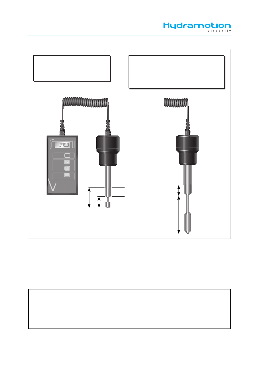
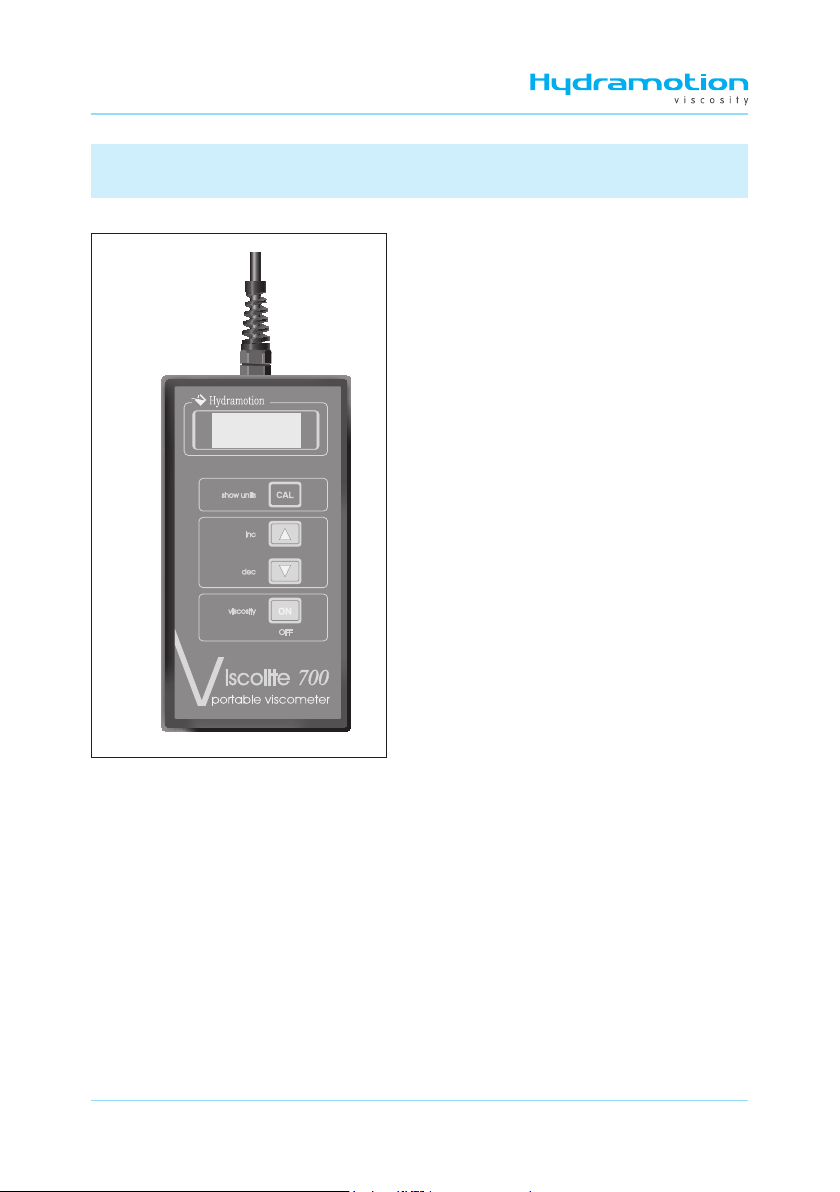
Figure 4
Display unit
2.1 Turning on
• Press the *key on the display unit and
hold it down for a second or two.
• The display shows a succession of digits
while the microprocessor goes through a
start-up routine. It will then show “VL”
briefly before settling on the “live viscosity”
reading. This is the dynamic viscosity
in centipoise (cP) of whatever fluid is
surrounding the sensor.
• The reading is updated every 1.5 seconds
approximately.
• Pressing the )or (keys will bring up two
other measurements, “t” (temperature) and
“VC” (temperature-corrected viscosity). For
more details, see pages 12 and 13.
• A beeper sounds each time a key is pressed.
• To switch off, press the *key again.
2.2 Operation check
• The display unit should read 0.0(zero) so long as the sensor is
(i) perfectly clean, dry and
(ii) wholly in air and not touching anything.
• The display should show 1.0 (exactly one) if the sensor is immersed in water at 20 °C.
For details of the checking procedure, see Section 5.2.
• If the air reading is not exactly zero:
(1) check that the sensor is perfectly clean, dry and not in contact with anything.
(2) if necessary, perform a “minor null adjustment” as described in Section 4.4 (p. 22).

Viscolite VL7
11
U01-04-013 R1 08/13
Figure 5
Measuring viscosity
2.3 Measuring viscosity
• Switch on the Viscolite.
• Immerse the sensor into the fluid to be measured to the depth shown in Figure 5.
• If the fluid is likely to be at a different temperature to that of the sensor, be sure to allow
sufficient time for complete temperature equalisation before taking a reading.
• The display unit shows the dynamic viscosity of the fluid in centipoise (cP), equivalent
to millipascal-second (mPa·s).
•Instability in the reading may be caused by
(1) temperature differences between the fluid and the sensor,
(2) the presence of suspended solids in the fluid, or
(3) a notable yield stress in a fluid exhibiting plastic behaviour (Bingham effect).
If the instability is caused by (2) or (3) (suspended solids or plastic behaviour), use the
probe to stir the fluid gently.
Do not clamp
below here
Do not clamp
below here
VL7-100B-d20 and VL7-100B-d21 VL7-100B-d15
A
B
Minimum immersion depths:
Bviscosity or temperature
Aviscosity only
A
B

Viscolite VL7
12 U01-04-013 R1 08/13
*The Viscolite operates at a very high shear rate, which helps to give it high repeatability. Many laboratory
viscometers operate at low shear rates. If the fluid is shear-thinning (pseudoplastic or thixotropic), the Viscolite
reading will be lower than that obtained with a low shear-rate viscometer. If the fluid is shear-thickening
(dilatant or rheopectic), the Viscolite will give a higher reading. See also Section 4.9 (p. 25).
• The viscosity reading may be noticeably higher or lower than expected if:
(1) the temperature of the fluid is significantly different from that at which the
reference measurement was made, or
(2) the sensor is not immersed to the depths shown in Figures 1 and 5, or
(3) the fluid is non-Newtonian and the reference measurement was made using a
significantly different shear rate*, or
(4) the fluid density is significantly higher or lower than the nominal factory setting of
1.0 g/cm3. In this case, enter the correct density value using the procedure described in
Section 4.8 (p. 24).
2.4 Measuring temperature
• Switch on the Viscolite.
• Ensure that the sensor is immersed to the depth shown in Figure 5.
• Press the )key. The display will show “t” (temperature) briefly, then the temperature
of the fluid surrounding the sensor.
• Allow time for the sensor to reach the fluid temperature before noting the reading.
• To return to viscosity measurement, press the (key. The display will show “VL” briefly
before showing the current live viscosity again.
2.5 Temperature-corrected viscosity
• If the display unit is showing live viscosity, press the )key twice or the (key once.
The display will show “VC” briefly and then temperature-corrected viscosity.
• For details of how to set the reference temperature, see Section 3.4 (p. 16).
• The displayed reading is calculated using the measured viscosity and temperature and
applying two correction factors specific to the fluid under test. See section 3 (p. 14) for
details of how to enter these correction factors.

Viscolite VL7
13
U01-04-013 R1 08/13
• To return to viscosity measurement, press the (key twice or the )key once. The
display will show “VL” briefly before showing the current live viscosity again.
2.6 General maintenance
• Check periodically that the instrument gives a zero reading in air.
• Clean the sensor after each measurement. It is not usually necessary to switch the
Viscolite off while cleaning. The sensor can withstand vigorous cleaning so long as the
shaft is not bent or distorted in any way.
• It may be necessary to carry out a calibration check if:
(1) signs of appreciable wear or abrasion are observed, or
(2) the instrument is dropped or knocked sharply.
• Carry out a calibration check immediately if the shaft does not look perfectly straight.
• Further calibration checks are not necessary if the instrument is still giving a zero
reading in air and a reading of 1 in water at 20 °C.
• If required, certain minor adjustments are possible, as outlined in Section 4 below
(p. 20). For any other calibration problem, please contact Hydramotion Ltd or its
representative for details of the Instrument Verification Service.
2.7 Guidelines for optimum performance
• Do not operate the instrument outside its specification. In particular, do not subject the
sensor to extremes of heat or cold.
• Remove the batteries if the Viscolite is to remain out of use for a prolonged period.
• Whenever possible, keep the transducer in its carrying case.
• Never leave the transducer resting on the sensor shaft.
• Never use the sensor as a lever or for any other non-measurement purpose.

Viscolite VL7
14 U01-04-013 R1 08/13
3 Temperature-corrected viscosity
3.2 E-format numbers
• The structure of an E-format number is:
• - E - is the exponent (always displayed as two digits).
• Int is the integer component of the number (always four digits).
• FrAC is the fraction component (decimal part) of the number (also four digits).
• To get the complete number, the sum of the integer and fraction components is
multiplied by 10 raised to the power given by the exponent. I.e.,
number = (Int + 0.FrAC) × 10E
• For example:
0.61280473 = 6128.0473 × 10–4
Thus the exponent - E - indicates how many places the decimal point should move to
the left (if negative) or right (if positive) of the number when expressed as “Int.FrAC”.
3.1 Introduction
• The Viscolite uses an internal algorithm to calculate temperature-corrected viscosity
from the measured live viscosity and the measured temperature. (For more details see
Appendix 1, p. 29.)
• To enable temperature-corrected viscosity readings to be calculated, it is necessary for
the user to enter
(1) the desired reference temperature, and
(2) correction factors specific to the fluid under test.
• To determine the correction factors, see Section 3.6 (p. 18).
• The correction factors (and some other parameters) are entered, stored and displayed
in “E-format”. Details of how to enter these parameters are given in Section 3.3 (p. 15).
- E - Int FrAC
- E -Int FrAC

Viscolite VL7
15
U01-04-013 R1 08/13
3.3 How to enter an E-format parameter
• Check that the Viscolite is switched on and displaying live viscosity (VL), temperature
(t), or temperature-corrected viscosity (VC).
• Press and hold down the +and (keys simultaneously for a second or two. The
display will show “VISC”. The instrument is now in “Setup Mode”.
• Navigate through the menus to the desired parameter using the (or +keys as
indicated in Figure 7 (p. 16) or (for calibration and adjustment) Figure 11 (p. 21).
• With the desired parameter displayed (e.g. P91), press +for 3 seconds (Figure 6 below).
• The display will show “- E -” briefly followed by the value of the exponent.
• To go to the integer component Int from the exponent, press (. To go to the fraction
component FrAC from the exponent, press ). To return to the parameter, press *.
• To change a displayed value:
(1) press +. The value will flash.
(2) Use the )or (keys to increase or decrease the value.
(3) When the desired value has been reached, press +again.
Figure 6 Entering numerical data in E-format: overview
Number - E - Int FrAC *
0.6059132781 – 04 6059 1328
–58.8009340804 – 02 – 5880 0934
43629.5787797 01 4362 9579
• Other examples:
*Note rounding of last digit.

Viscolite VL7
16 U01-04-013 R1 08/13
3.4 Setting the reference temperature
• Put the instrument into Setup Mode as described in Section 3.3 (p. 15), so that “VISC” is
showing on the display.
Figure 7
Overview of the temperature-correction menu. Use the <or >keys to navigate
through the sub-menus (e.g. to go from P90 to P91, etc).
Details of the Calibration and adjustment menus are given in Section 4 (p. 20).

Viscolite VL7
17
U01-04-013 R1 08/13
Figure 8 General functions of keys
ON
CAL
exits a sub-menu.
move up or down through a menu or a sub-menu, or
increase or decrease a numerical value.
accesses a sub-menu,
enables a numerical value to be changed, or
fixes or burns a numerical value.
3.5 Saving changes
• Any newly-entered value will be lost on power-down unless it is “burned” into
permanent (non-volatile) memory. To do this:
(1) Navigate through the relevant menu(s) to burn .
(2) Press +for 3 seconds. The display will show “b uSY” briefly as the data is saved.
• The “burn” can be done at any time before powering-down the Viscolite. It is not
necessary to save the data after each entry.
• Press (twice. The display will show “VC” (see temperature-correction menu, p. 16).
• Press +. The display will show “P90” briefly, then its value.
• Press (twice. The display will show “trEF” (reference temperature) briefly, then its
value in °C. The factory default setting is 15.0.
• Press +. The display will begin to flash.
• Use the (or )keys to change the value as required.
• Press +. The value will cease flashing.
• Press *. The display will revert to “VC”.
• Return to normal operating mode (“VL”) using the )and *keys as indicated on the
menu on p. 16.
• If required, save the change as described in Section 3.5 below before switching off the
Viscolite.

Viscolite VL7
18 U01-04-013 R1 08/13
The calculation is:
where
V1= viscosity at temperature t1°C
V2= viscosity at temperature t2°C
• If possible, use values of t1and t2that are close to the fluid temperature and the
reference temperature.
• Enter the calculated value of P91 as described in Section 3.3 (p. 15).
• If required, save the value as described in Section 3.5 (p. 17) before switching off the
Viscolite.
3.6 Determination of temperature correction factors
• The correction factors are called P90 and P91 (see p. 30). The first of these (P90) is
simply an offset and can be left at zero. The factory default setting for P91 is also zero.
• There are two ways of determining P91: (i) calculation and (ii) trial-and-error.
(i) Calculation of P91
• To calculate P91, it is necessary to know the viscosity of the fluid at two temperatures.
Figure 9
Calculation of P91
VISCOSITY
TEMPERATURE (°C)
t1t2
V2
V1
typical viscosity/temperature
characteristic
logeV1– logeV2
[1/(t1+ 273)] – [1/(t2+ 273)]
P91 =

Viscolite VL7
19
U01-04-013 R1 08/13
(ii)Trial-and-error determination of P91
• This method can only be used if
(a) variation in fluid temperature is causing the live viscosity reading (VL) to fluctuate,
and
(b) it is known that the temperature-corrected viscosity would be stable, i.e. truly
constant, despite the fluctuations in VL.
• Using the (or +keys as indicated in Figure 7 (p. 16), navigate through the
temperature-correction menu to P91.
• Enter a value of 5000 (- E - = 00, Int = 5000, FrAC = 0000) as described in Section 3.3.
• Navigate to VC. Note the degree of fluctuation in the reading.
• Go back to P91 and enter a higher value, say 5250 (- E - = 00, Int = 5250, FrAC = 0000).
• Go back to VC and see if there is more or less fluctuation in the reading.
• If the reading is fluctuating less, go back to P91 and increase the value again. Check the
amount of fluctuation in the VC reading. Continue in this way until VC stabilises.
• If the reading is fluctuating more, go back to P91 and reduce the value. Check the
amount of fluctuation in the VC reading. Continue in this way until VC stabilises.
• If required, save the value as described in Section 3.5 (p. 17) before switching off the
Viscolite.
TIME
VISCOSITY / TEMP
TIME
VISCOSITY / TEMP
TIME
VISCOSITY / TEMP
P90 = P91 = 0 P91 CHANGED
P91 FINE TUNED
VL
VC
TEMP
VL / VC
TEMP
VL
TEMP
VC
VL
TEMP
VC
Figure 10
Trial-and-error
determination
of P91

Viscolite VL7
20 U01-04-013 R1 08/13
4 Operational adjustment
4.1 Introduction
• Minor operational adjustments are carried out using the Calibration and adjustment
menus shown in Figure 11 (p. 21).
• The following adjustments can be made:
Reference Page
correct small non-zero reading of viscosity in air Section 4.4 22
stabilise reading (especially in high-noise conditions) Section 4.5 22
scale reading by any desired factor Section 4.6 23
take account of fluid density Section 4.7 24
express reading in centistokes (cSt) Section 4.8 24
match Viscolite to reference viscometer Section 4.9 25
4.2 How to modify a numerical value
• Parameters stored in “E-format” must be changed as described in Section 3.3 (p. 15).
• Other items are changed as follows:
(1) Navigate through the appropriate menu(s) until the desired item is reached.
(2) The name of the item will appear briefly, followed by its value.
(3) Press +. The value will flash.
(4) Use the (or )keys to decrease or increase the value as desired.
(5) Press +again. The value will cease flashing.
(6) To go to the next item in the same submenu, press (.
(7) To go to the previous item in the same submenu, press ).
(8) To exit the submenu, press *.
This manual suits for next models
1
Table of contents
Popular Measuring Instrument manuals by other brands

BRONKHORST
BRONKHORST Mini CORI-FLOW MI Series instruction manual

Spectroline
Spectroline EZ-Ject AC&R Dye instruction manual

Sealey
Sealey MS100 instructions

PCB Piezotronics
PCB Piezotronics ICP TLD333B31 Installation and operating manual

Sloan
Sloan Optima Maintenance manual

Polytec
Polytec PDV-100 user manual

Spectrum
Spectrum Fieldscout 2265FS product manual

General
General DSMM600 user manual

Juniper
Juniper 4VETJ user manual

Dwyer Instruments
Dwyer Instruments WDPM-002 Specifications-installation and operating instructions

Delmhorst Instrument Co
Delmhorst Instrument Co F-2000 owner's manual

Projecta
Projecta BM320 instruction manual