VÁLVULA AUTOMÁTICA
DE INSERCIÓN EN LA
TUBERÍA
Instrucciones de funcionamiento
Modelo HRP-100
Garantía de tres años
Fijación de las válvulas
Después de purgar las tuberías, instale la válvula en el conector del distribuidor
PVC-Lock®o en el conector PVC-Lock®. La toma de la válvula es un tubo de PVC
de 1" (2.5 cm), dimensionado para la instalación en conectores PVC-Lock®de 1"
(2.5 cm) o conectores deslizantes de PVC de soldadura con solvente. Observe la
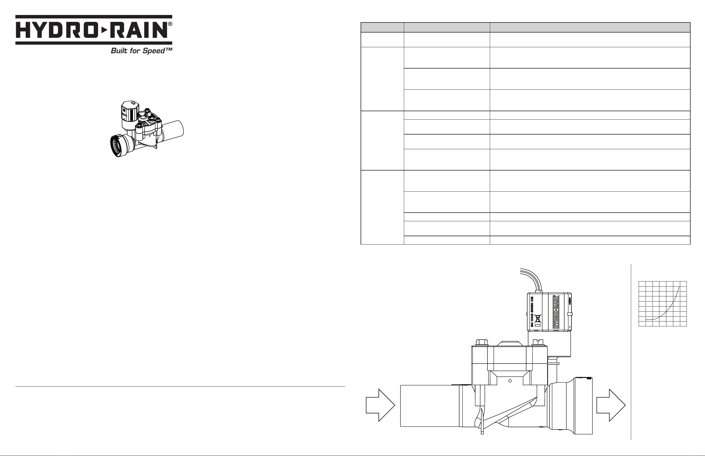
dirección de las flechas para la dirección del flujo de agua.
Fijación de las tuberías del aspersor
Fije las tuberías del aspersor a la toma Blu-Lock®de 1" (2.5 cm) de la válvula.
El tubo de polietileno "Poli" de 1" (2.5 cm) o SIDR 15 o SIDR 19 es compatible con
la toma Blu-Lock®. Tanto los conectores PVC-Lock®como Blu-Lock®se pueden
retirar con las herramientas de remoción PVC-Lock®o Blu-Lock®, por lo tanto no
es necesario el uso de uniones.
Introducción del cable
Con la electricidad desconectada, conecte las válvulas a un controlador Hydro-
Rain®(u otro temporizador que utilice un transformador clase 2 de 24 voltios
aprobado por UL®como fuente de alimentación). Utilice un cable revestido de
múltiples hilos y colores para aspersor. Compruebe que el cable tenga al menos
un hilo más de cable que el número de válvulas del distribuidor. Cave y pase el
cable hasta las válvulas. En áreas donde se cave con frecuencia, se recomienda
que utilice una sección de tubo de PVC como cubrimiento protector para el cable.
Conexión del cable
Conecte el cable común a un cable en el solenoide. Conecte el cable de zona o el
activo al otro cable del solenoide.
Pruebe el sistema
Después de que todos los tubos y conectores estén instalados (permiti-endo
suficiente tiempo para que las juntas con pegamento PVC sequen (24 horas si
no utiliza PVC-Lock®), abra el suministro de agua y revise si hay goteo con las
válvulas cerradas. Las válvulas pueden abrirse en cualquier momento mientras
se presuriza la tubería inicialmente pero se cerrarán en un momento después
de que salga el aire del sistema.
Válvulas abiertas
Gire el solenoide (sentido antihorario) para abrir manualmente la válvula. Revise
la tubería descendente y los conectores en busca de fugas. Cierre la válvula
girando el solenoide en el sentido horario hasta que aumente la resistencia. El
cierre de la válvula puede tomar varios segundos ya que la presión se acumula
para cerrar la válvula. El sistema está listo ahora para que el temporizador lo
controle eléctricamente.
Vaciado
En climas con temperaturas de congelación, las válvulas y las tuberías se
deben vaciar. Para comprobar que las válvulas eléctricas estén completamente
vaciadas, cierre la válvula de cierre del aspersor principal y haga funcionar cada
válvula en seco unos minutos. Gire el temporizador a la posición "off" (apagado)
hasta la primavera.
Notas:
• Para uso en exteriores con agua fría solamente. Las válvulas se deben colocar
de forma que el agua drene opuesta a la casa. Si no utiliza agua potable, debe
utilizar un filtro después de la(s) válvula(s).
• Todos los distribuidores deben estar elaborados con conectores PVC-Lock®o
tubo y conectores de PVC cédula 40. El uso de los conectores de distribuidor
PVC-Lock®de Hydro-Rain®es un método fácil de elaborar un ensamble de
distribuidor de servicio expansible y fácil.
• Las regulaciones locales especifican la ubicación y el tipo de válvulas
requerido. Revise las regulaciones locales para los requisitos de instalación.
• Si la presión estática del agua supera los 80 psi (5.5 bar), se debe utilizar un
regulador de presión.
• Siempre que sea posible, proteja las válvulas con una caja para válvulas y
coloque gravilla en la base.
• Pruebe la presión de todas las tuberías de agua antes y pruebe las conexiones
eléctricas de todos los temporizadores antes de cubrir el tubo y el cable de
control del temporizador.
Resolución de Problemas
El Problema Verifique Si Solución
La válvula no abre La válvula está instalada incorrectamente Compruebe que las flechas de la válvula estén en la dirección del flujo del agua. Revise la presión
del agua de la tubería de suministro de agua.
La válvula no abre
electrónicamente
El cableado y el temporizador están
incorrectamente instalados
Examine el cable a la válvula y al programador (revise a las instrucciones para el programador).
También, asegure que el programador está funcionando en forma correcta incluido el
transformador del programador, el fusible ( o el butón de reset ) y la programación.
Hay partículas en el agujero del puerto
Cierre el agua. Quite el solenoide. Inserte un cable o un cable de metal en el orificio para asegurar
que no esté obstruido. Asegúrese que el pistón y la compuerta o (o-ring) se haya colocado
correctamente especialmente cuando se vuelva a colocar o montar el solenoide.
Solenoide defectuoso
Cierre el suministro de agua. Desenrosque el solenoide y reemplácelo con otro de una válvula que
esté funcionando. Si la válvula funciona ahora, reemplace el solenoide defectuoso. Compruebe que
la junta tórica esté en su lugar cuando vuelva a ensamblar.
La válvula no
cierra
La válvula está instalada incorrectamente Verificar que las flechas vayan en dirección del flujo del agua.
Solenoide defectuoso Compruebe que el elevador manual de desagüe este en posición cerrada (en dirección de las
manecillas del reloj).
Hay piedras o partículas entre la
arandela y el asiento de la válvula.
Cierre la llave del agua. Quite el solenoide y lávelo para que no contenga arena ni desechos,
compruebe que el pistón y la compuerta o (o ring) se hayan colocado en el lugar indicado cuando
se vuelva a montar.
El filtro del diafragma está atascado
Cierre el suministro de agua. Retire la tapa y compruebe que el agujero del diafragma con
depurador del filtro no tenga partículas. Mueva el depurador del filtro hacia arriba y hacia abajo en
el agujero y limpie las partículas.
La válvula externa
gotea
El lado de entrada del grifo de la válvula
no está completamente insertado en el
conector PVC-Lock®
Compruebe que el conector de entrada de la válvula esté insertado en el conector PVC-Lock®al
menos 1" (2.5 cm). Confirme que no haya daños en el sello del PVC-Lock®ni en la superficie de la
toma de la válvula que pudieran ocasionar fugas.
El tubo Blu-Lock®está incorrectamente
instalado en la salida
Revise que la tubería Blu-Lock®esté completamente insertada a una profundidad de al menos
1" (2.5 cm). Retire el tubo del soporte Blu-Lock®, así como las partículas y revise el sello y el
diámetro externo del tubo en busca de daños.
La presión está demasiado alta Instale un regulador de presión antes de la válvula y configúrelo a 80 psi.
El agua gotea alrededor de los tornillos
Cierre el suministro de agua. Retire la tapa y confirme que el diafragma esté correctamente
colocado en las ranuras adecuadas. Revise si hay partículas o daños en el cuerpo de la válvula, la
tapa y el diafragma.
Goteo del solenoide a la junta de la tapa Cierre el suministro de agua. Confirme que la junta tórica del solenoide no esté dañada o faltante.
Hydro-Rain®Tres Años De Garantia Limitada
Hydro-Rain®garantiza a sus clientes que sus productos Hydro-Rain®estarán libres de desperfectos en material y mano de obra por un
período de tres años a partir de la fecha de compra. La compañía reemplazará, sin cargo alguno, la parte o las partes que se compruebe
que se hayan deteriorado con un uso normal, por un período de tres años a partir del momento de efectuada la compra. Hydro-Rain®se
reserva el derecho de inspeccionar la parte defectuosa antes de reemplazarla. La compañía no se hace responsable de ningún costo por
daños causados por el desperfecto del producto. La responsabilidad de Hydro-Rain®dentro del marco de esta garantía se limita sólo al
cambio o reparación de las partes defectuosas.
Los requisitos elétricos
mínimos son de 18 voltios
de corriente alterna (A.C.)
en el solenoide
Volt-amps de entrada
@ 24 VAC = 11.5 VA
Corriente de entrada
@ 24 VAC = 0.48 AMPS
Retención de volt - amps
@ 24 VAC = 5.75 VA
Corriente de retención
@ 24 VAC = 0.24AMPS
Diagrama
de perdida
de presión
para válvula
en linea
Hydro-Rain
North Salt Lake,
UT 84054
888-493-7672
801-203-1179
hydrorain.com
ACables que van al programador
BSolenoide de bajo voltaje
CLado con presión estática del agua
DA las cabezas del sisterna de aspersores
Conponentes
C D
B
A