Hydro Tek CN Series Manual

$15.00
OPERATION & MAINTENANCE
MANUAL
IMPORTANT: CAUTION! TO REDUCE RISK OR
INJURY, READ OPERATING INSTRUCTIONS
CAREFULLY BEFORE USING
ULTIMATE LINE
POWER WASHERS
CN SERIES
CP SERIES
CW
SERIES
HP SERIES
HX SERIES
SC SERIES
SS SERIES
© Hydro Tek . 1/2007

TURBO
NOZZLE
ADJUSTABLE
PRESSURE WAND CHEMICAL
INJECTORS
SAND
BLASTER
HOSE EXTENTIONS HOSE REELS
WASH WATER RECYCLE / RECOVERY / FILTRATION
The ANT38 HYDRO TWISTER is a unique surface
cleaner with a 38” cleaning path. The impressive size and
construction allows the operator to maneuver and clean
wide areas in one pass. Suitable for use on greasy factory
floors, concrete parking lots and drive thru areas, gas
stations and garages.
Advantages...
• Stainless steel construction for lifetime corrosion
resistance. Saves time, money and fatigue.
Specifications...
Up to 4000 PSI
Up to 5 - 7 GPM
38” Cleaning Path
Temperatures up to 200° F
The Hydro Twister ANT20 and ANT28 are surface
cleaners that connect to a pressure washer and uses
two nozzles rotating at a high RPM within 1” of the
ground. It will clean concrete at up to 15 times the speed
of an operator using a wand and with more consistency
and less operator fatigue. Simply move the
twister over the surface and watch a clean
path appear behind the unit.
Advantages...
• Three Stainless Steel Sealed Bearings:
Requires no maintenance
• Carbide Seal Design: Offers long life at
high temperatures
• All Stainless Steel Construction: Provides
lifetime corrosion resistance.
Specifications...
Up to 4000 PSI
Up to 10 GPM (5 GPM Standard)
20” or 28” Cleaning Path
Temperatures up to 250° F
XBTIJOH!BDDFTTPSJFT
HYDRO TWISTER®SURFACE CLEANERS
Bmm!sjhiut!sftfswfe!!3118/!Tqfdjgjdbujpot!nbz!wbsz
The ANT3C Contractor Series HYDRO
TWISTERS are the proven choice for
professional surface cleaning with three
options for your cleaning needs. The
ANT3C is a 3-in-1 rotary surface cleaner
and includes a spot / gum remover and a
hydro broom creating an all-in-one portable
system. The dual trigger gun control allows
you to activate either device simply by pulling
the appropriate trigger. By combining three
processes into one unit, you will save time
and fatigue when cleaning large expanses of
concrete, parking lots or other flat surfaces.
The secret that makes the Contractor Hydro
Twister so effective is the water spray angles
and nozzle heights optimizing the unit for
maximum cleaning power.
Use the water broom function to power away
debris and dirt in a 28” wide swath and the
job is done.
Advantages…
Multipurpose: One unit
includes a gum & spot
remover, water broom and
a rotary cleaner to get jobs
done faster.
Stainless Steel Construction:
HeavyDuty,lifetimecorrosion
resistance.
High Productivity: Cleans
up to 15 times faster than
an operator with a handheld
wand.
Specifications...
Up to 4000 PSI
28” Cleaning Path
Up to 10 GPM (5 GPM Standard)
Temperatures up to 250° F
•
•
•
ANT20 has lightweight
composite deck
Integrated water broom and spot remover
TANK SKIDS
TRAILERS
200 - 500 Gallon
IZESP!MPPQ
WASH - CONTAIN - RECYCLE
OTHER ACCESSORIES

TABLEOFCONTENTS 3
INTRODUCTION .................................................................................................................................. 4
Statement of Warranty
SAFETYWARNINGS ........................................................................................................................... 5-6
Electrical Precautions
Fire Precautions
Ventilation Precautions
Spray Injection Precautions
Personal Hazard Precautions
OPERATING INSTRUCTIONS ........................................................................................................... 7-8
Before Start Up
Operation
Shut Down & Antifreeze Protection
SYSTEM INFORMATION ................................................................................................................. 9
Chassis and Trailer Assembly
Power System ............................................................................................................................. 9
Electric Motor/Gasoline Engine/Diesel Engine
Power Transmission System - direct, & belt drive
Generator - auxiliary power, circuit breaker
Pumping System ........................................................................................................................ 10-11
Pump
Unloader and Pressure Relief Valve
Chemical Injection System - inlet & downstream injection
Water Supply - direct, float tank, & supply tank feed
Heating System .......................................................................................................................... 11
Coil/Heat Exchanger System - temperature & flow switch controls, lights ...................... 11-12
Diesel Fired Burner - air band, transformer, fuel pump, filter, & solenoid
Pressure Delivery System ......................................................................................................... 12-13
Discharge Hose
Gun/Wand Assembly - trigger gun, wand, & quick coupler
Nozzles - spray nozzles and steam nozzle
Accessories - wet sandblaster, turbo nozzle, hoses and reels, wands, injectors ............... 14
Hydro Twister, Hot Water Jetter
TROUBLE SHOOTING GUIDE ....................................................................................................... 15-16
WIRING DIAGRAMS BY SERIES .................................................................................................... 17-23
SERVICE/MAINTENANCE INFORMATION ................................................................................ 24
EXPLODED VIEW ........................................................................................................................ Enclosed
TEST SPECIFICATIONS ................................................................................................................ Enclosed
ENGINE SHEET ............................................................................................................................ Enclosed

INTRODUCTION 4
INTRODUCTION:
THANKYOU:Theemployeesandmanagementof
HYDROTEKSYSTEMS,INC.thankyouforselecting
ourproducts. Theproductionandqualityassurance
personnelhavetakenthegreatestcareintheassembly
processtoensurethatyournewIndustrialCleaning
Equipmentexceedsthestandardssetbyyou,the
customer,byHydroTekengineeringandmanagement,
andbyoursafetycertificationtoU.L.1776.
YOURRESPONSIBILITY:Thisoperator’smanual
wascompiledforyourbenefit. Bystudyingand
followingthesafety,installation,operation,maintenance,
andtroubleshootinginformationcontainedwithin,youcan
lookforwardtomanyyearsoftroublefreeservicefrom
yourequipment. Everypersonwhowilloperatethe
equipmentmustreadandfollowthesafetywarningand
operatinginstructionsectionsofthisowner’smanual
priortouse. Youareresponsibleforoperatingthe
productproperlyandsafely.Youarealsoresponsibleto
followthemaintenancescheduleonthebackpageofthis
manualtokeepyourwarrantyactive.
FREIGHTDAMAGE:Ifdeliveredbytrucking
company,pleaseinspectforanyconcealedfreight
damageandnotethisonthepaperworkfromthetrucking
companybeforesigning. Shouldyoufinddamagehas
occurredduringshipping,donotreturnthedamaged
merchandisetoHydroTek,butfileaclaimimmediately
withthefreightcarrierinvolved.
QUESTIONS:Helpusprovideyouwiththefastest
service. Pleaselocatetheenclosedwarrantyregistration
cardandreturnittoHydroTektoregisteryourmachine.
ContactyourlocalAUTHORIZEDHYDROTEK
SERVICEDEALERthatyoupurchasedfromorcall
HYDROTEKfactoryand askfortechnicalservicesif
problemsoccur. THEREARENOUSER
SERVICEABLECOMPONENTSONTHIS
EQUIPMENT.
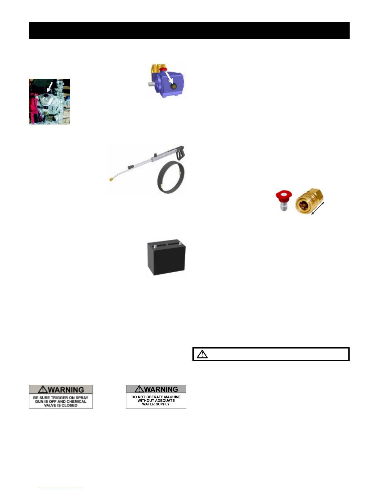
GETTINGSTARTED:Ifyourdealerhasnotprepared
themachineforstartup,youmayneedtoconnectthe
hoseto the pressureoutlet on thewasherand connect
theotherendofthehosethatswivelstothetriggergun
inletandtighten. Thewaterwillberemovedoranti-
freezesolutionwillbeaddedtothepumpandcoil.
MobileWashSkidsareenginepoweredandshipped
fromthefactorywiththefueltanksempty,thebattery
cablesdisconnected,thebatterydry(ifincludedon
enginepoweredunits). Fillthebatterytothefilllinewith
electrolyte(availableatalocalautopartsstore),connect
thebatterycables,andfollowtheoperationinstructions
forstarting. Pressure Steamers areelectric powered
andwillrequireanappropriateelectricoutletor
disconnectboxandanelectricplugthatisratedforyour
machine’svoltageandamperageandmatchestoyour
electricalsocket.Smallermachinesareequippedwitha
groundfaultinterrupterontheelectricalcordandyouwill
needtopressthe reset buttonafteritispluggedin. (See
OperatingInstructionssectionandenclosedpageon
InstallationGuidelines).
NO-NONSENSEGUARANTEE:
HydroTekSystems,Inc.(HydroTek)promisestorepair
UltimateandProlinewashersifdefectiveinmaterialsor
workmanshipforoneyearfromthedateoforiginalretail
purchaseincludingthecostsofPARTSandLABOR,but
youmustpaytransportationcostsandtraveltime.
ItemsandConditionsNotCovered:
1.Normalwearitemssuchasdischargehose,guns,
wands,sprayarms,nozzles,quickcouplers,o-ring,
pumppacking,brushes,filters,belts,andtires.
2.Costofregularmaintenanceoradjustmentsor
damagefromlackofmaintenance.
3.Damageduetofreezing,abrasivefluids,chemical
deterioration,andscalebuildup.
4.Damagefromfluctuationinelectricalorwater
supply.
5.Anyproductorpartwhichhasbeenaltered,modified,
overpressurized,misused,orbeeninanaccident.
6.Dealerinstallationordamagefromimproper
installationofthemachineoralterationbyadealeror
promiseofadditionalwarrantyfromdealer.Thefactory
warrantyisnottransferablefromthedealertotheretail
purchaseronusedorrentedequipment.
7.Laborisnotpaidifthedealerthatservicedyour
machineisnotanauthorizedservicecenter.
8.Laborisnotpaidonaddedaccessoriessuchas
surfacecleaners,hosereels,wastewaterrecycler, and
vacuums.
WARRANTYPROVIDEDBYOTHERS:Gasoline,
dieselenginesandsomeelectricmotorsarewarranted
bythemanufacturerofthemotorandtheirwarrantyis
providedthroughthemanufacturer'sservicecenters.
BIG6COILREPLACEMENT:Shouldtheheatercoil
leakundernormalconditionswithinthefirst6yearsof
service,HydroTekwillprovideareplacementcoilfree
ofcharge. Failurefromfreezingorfreightand
installationlaborexcluded.
GENERALCONDITIONS:
HydroTek'sresponsibilitywithrespecttoclaimsis
limitedtomakingtherequiredrepairsorreplacementsto
theoriginalretailuser,andnoclaimofbreachof
warrantyshallbecauseforanycancellationorrescission
ofthe contractof sale ofany HydroTek product. Hydro
Tekreservestherighttochangeorimprovethedesignof
anyofitsproductsorillustrationswithoutassumingany
obligationtomodifyanyproductpreviously
manufactured.
Thissupersedesanyandallpreviouswarranty
statementsforproductspurchasedafterJanuary1,2007.
HydroTekisnotliableforindirect,incidentalor
consequentialdamagesincludinganycostofsubstitute
equipment,lossofrevenue,pecuniaryexpenseorloss,or
anydamageswhatsoeverarisingoutoftheuseor
inabilitytouseaHydroTekproduct.HydroTek
disclaimsallimpliedwarranties,includingthoseof

or breakdown, grounding provides a path of least
resistance for electric current to reduce the risk of
electricshock. Thisproductisequippedwithacord
havinganequipment-groundingconductor. Theplug
must be plugged into an appropriate outlet that is
properlyinstalledandgroundedinaccordancewithall
localcodesandordinances.
Danger-Improperconnectionoftheequipment-ground-
ing conductor can result in a risk of electrocution.
Checkwithaqualifiedelectricianorservicepersonnel
ifyouareindoubtastowhethertheoutletisproperly
grounded. Donotmodifytheplugprovidedwiththe
product,donotcutoffthegroundpin-ifitwillnotfitthe
outlet, have a proper outlet installed by a qualified
electrician. Donotuseanytypeofadaptorwiththis
product.
4. Tocomplywiththenationalelectriccode,thispressure
washershouldonlybeconnectedtoareceptaclethatis
protectedbyagroundfaultcircuitinterrupter(GFCI).
5. EXTENSIONCORDS:
Useofextensioncordsisnotrecommended.
6. NEVERoperateanelectricallypoweredwasherafter
ithastrippedabreakeroragroundfaultdevicewithout
havingthereasonforthetripdeterminedbyanautho-
rizedserviceengineerorcompetentelectrician.
7. Useonlyinadryarea. Donothandleelectricalcords
andplugswhentheyarewet,whenyourhandsarewet,
orwhenstandinginwater. Donotsprayhighpres-
surewaterontothemachine.
8. Disconnectpowersupplybeforemakinganyrepairsor
adjustments.
9. Transformer on burner is 20,000 volts. Disconnect
batterycablebeforeservicingburnerorengineon12
voltsystems.
FIRE PRECAUTIONS:
1. DONOTuseimproperfuelsorsolventsinthisequip-
ment,andonlyfillwiththecorrectfluidswhentheunitis
inanOFFcondition,mainpowerisdisconnected,and
engineandburnerarecool.
ELECTRICALPRECAUTIONS:
1. Observe all State, Local, and National codes for
theinstallationofyourelectricallypoweredwasher.
2. Foragroundedproductrated250volts,singlephase,
orless:ThisProductIsProvidedWithAGroundFault
CircuitInterrupterBuiltIntoThePowerCordPlug. If
Replacement Of The Plug Or Cord Is Needed, Use
OnlyIdenticalReplacementParts.
3. GROUNDINGINSTRUCTIONS:
CordConnected,GroundedProducts:
Thisproductmustbegrounded. Ifitshouldmalfunction
IMPORTANT SAFETYWARNINGS:SAVE THESE INSTRUCTIONS 5
Warning: FIRE OR EXPLOSION HAZARD CAN
CAUSE SEVERE INJURY OR DEATH AND PROP-
ERTYDAMAGE
merchantabilityandfitnessforuseforaparticular
purpose. Somestatesdonotallowexclusionsor
limitationsonhowlonganimpliedwarrantylasts,sothe
aboveexclusionsmaynotapplytoyou. Itisthebuyer's
responsibilitytoensureinstallationanduseofHydroTek
productsconformstolocalcodes. Productsexported
outsidetheUSandCanadaarecoveredsolelybythe
warrantyofthelocalexportdealerandthiswarranty
doesnotapply.
HOWTOOBTAINWARRANTYSERVICE:
1.Write down your model #_________________and
serial #________________(on base plate of machine
nearthemotor).
2.ContactyourlocalservicedealerandreturntheHydro
Tekwasherorpartwithinthewarrantyperiodalongwith
yoursalesreceipt.Tolocateservice,callthefactoryand
askfortechnicalservicesorgotowww.hydrotek.us
3.Youmayalsoshipthedefectivepartfreightprepaid
directlytothefactoryifyoucontacttechnicalservices
firstandwewillissueyouareturngoodsauthorization
andthenrepairorreplaceundertheconditionsof
warranty.Wewillpaythecostofreturningitbacktoyou
byamethodofourchoice.
4.Ifthedefectivecomponentisanengineormotormade
byanothermanufacturer,yourauthorizedHydroTek
dealerorwecanhelpyouobtainwarrantyservice
throughthespecificmanufacturer’slocalauthorized
servicecenter.
5.Ifyouareunabletoresolvethewarrantyclaim,write
toHydroTekSystems,Inc.,2353AlmondAve,
Redlands,CA92374.Attn:TechnicalServices. Please
encloseacopyofthedatedpurchasereceiptandexplain
the nature of the defect.

IMPORTANT SAFETYWARNINGS:SAVE THESE INSTRUCTIONS 6
2. Fill the diesel burner fuel tank with #2 diesel fuel or
kerosene.NEVERusegasoline. Donotconfusegaso-
lineandfueloiltanks. Keepproperfuelinpropertank.
3. NEVER operate this equipment in the presence of
flammablevapors,dust,gases,orotherpotentially
combustiblematerials.
4. AVOIDcontactwiththeexteriorofthecoil/heat
exchanger assembly, mufflers, and exhaust stack to
preventburns.
5. DONOTstorefuelorotherflammablematerialsnear
theburneroranyotheropenflame.
6. ToavoidburnsNEVERstandoverburnerexhaust
outletorinfrontofengineexhaust. Burnermaystartat
anytimeoncepoweristurnedon.
7. Donottouchburnerexhaustport,mufflers,orhosesas
contactmaycauseburns.
8 Dieselfiredorgasolinepowerunitsaredesignedfor
outdooruseandinstallationonly.
9. Burneron/offswitchmustbeplacedintheOFFposition
when the pressure washer is not being used. Do not
dependonenginerunswitchtoturntheburneroff-This
maycauseasafetyhazard.
VENTILATION PRECAUTIONS:
1. DO NOT run engine or burner in an enclosed area.
Exhaustgasescontaincarbonmonoxide,anodorless
deadlypoison.
2. ObserveallState,Local,andNationalcodesproviding
forindooruseorinstallationofthisunit.
3. Provideadequate ventilationtopreventengine
overheatingandinefficientburnercombustion
(minimum2'ofairspace).
SPRAY INJECTION PRECAUTION:
1. Fluidfromhighpressuresprayorleakscanpenetratethe
skinandcauseseriousinjury. Ifanyfluidappearsto
penetratetheskingetemergencymedicalhelpatonce.
DONOTtreatasasimplecut. Tellthephysicianexactly
whatfluidwasinjected. Fortreatmentinstructionshave
thephysiciancallyour localpoisoncenter. Without
propertreatment,complicationscandevelop.
2. WARNING - Risk of injection or severe injury to
persons - Keep clear of nozzle. DO NOT direct dis-
chargestreamatpersons.Thismachineistobeusedby
trained operators. Keep operating area clear of all
persons. Useonly48"longwandsonmachinesproduc-
ing over 3000 psi. Also, only use straight wands or
wandswithabendof10°orless.
CAUTION:Hotdischargefluid-DONOTtouchor
directdischargestreamatpersons.Gunkicksback-
Holdwithbothhands. Stayalert-Watchwhatyou
aredoing.
3. Alwayswearprotectiveeyegoggleswhenoperating
theequipment. Additionalprotectiveitemssuchasa
rubbersuit,gloves,andrespiratorsareadvisable,
particularlywhenusingcleaningdetergentswitha
corrosivecontent.
4. Knowthedetergentsyouareusing. Readandfollowthe
directionsonthedetergentlabels.
PERSONAL HAZARD:
1. DONOTremovebeltguardsorelectricalcoverswhile
engineisoperatingorwhenthepowerisconnected.
2. DONOTmoveenginepoweredmachinerywhilethe
engineisoperating.
3. DONOTlockthetriggeronthegunvalveintheon
position.
4. DONOTexceedrecommendedoperatingpressure
ortemperature.
5. Observeallregulationswhentowingtrailermounted
units.
6. KEEPHandsClearOfBelts:Someunitsequipped
with auto on may start at any time when power is
connected.
7. Donotoperatetheproductwhenfatiguedorunderthe
influenceofalcoholordrugs.

BEFORE START UP:
1. Read all instructions before using this product.
2. CHECK OIL AND FLUID LEVELS:
Check pump oil by locating the oil view
window and fill to the red
dot. On the SC and SS
series fill to the top of the
sight glass window. Check fuel levels.
Checkengineoilandcoolantlevelsifunitis
so equipped. (See the maintenance sched-
ule on page 9).
3.CONNECT HOSE AND GUN ASSEMBLY.
4. CONNECT THE WATER
SUPPLY & TURN
WATER ON:
Maintain an adequate sup-
plyofwaterusinga¾"I.D.
hose with a pressure be-
tween 25 and 60 PSI.
Burner power switches should be off before starting. If
tank fed, be sure there is water in the tank and the valve
is switched for supply tank feed. Do not run dry for
longer than one minute.
5. BATTERY INFORMATION:
The battery is included on all Ultimate
Line machines and will have to be filled
with electrolyte (available at local auto
parts store).
!WEAR EYE PROTECTION!
If the opening on your battery box measures 9" by 6"
we recommend Exides' U1L/GTH 235CCA battery. If
the opening measures 8" by 12" we recommend
Exides' group 46-60 550 CCA battery. Deep cycle
batteries are recommended to extend battery life.
Always connect the positive battery cable before the
negative and coat the battery terminals with corrosion
inhibitortopreventcorrosion.
6. If wheel kit, accessories, or discharge hose are not
installed, see your local dealer for instructions &
installation.
OPERATION:
1. STARTING:
A. Electric Powered Units:
Connect power supply and ensure that all wiring
connections and voltages are of sufficient rating to
complywiththeequipment'srequirements. Turnpump
power switch on. If unit is equipped with auto-start,
keep all power switches off when left unattended.
(Unitwillonlyturnonwhentriggergunispulled.)Unit
will shut off 60 seconds after trigger is released.
B.GasolineEngineUnits:
Turn engine power switch to the on position, choke if
necessaryandturnkeytostartpositiononlyuntilengine
starts. Onunitswith arewindstarter,pullcordrapidly.
C. DieselEngineUnits:
Turn power switch to heat the glow plugs for a maxi-
mumof30seconds andrelease. Turnthepowerswitch
tothestartpositiononlyuntilenginestarts. (Donotuse
starter fluids)
2. PURGE AIR FROM SYSTEM:
Squeeze the trigger on the spray gun until a constant
stream of water comes out. (Purging works best with
nozzle removed from wand and/or dual wand in the low
pressure mode.
3. SELECT DESIRED
NOZZLE &
Connect nozzle securely
to spray wand. If equipped,
close pressure adjusting knob on dual wand. Hold gun
firmly, squeeze trigger for high pressure spray.
CAUTION - Gun kicks back - hold with both hands.
WARNING - Risk of explosion - DO NOT spray
flammableliquids.
4. START BURNER:
To create hot water on high pressure washers equipped
withheatexchangers,release the triggeronthegun,turn
theburnertothe"on"position,andturnthethermostatto
the desired temperature.
Squeezethetriggeronthespraygunandtheburnerwill
begin heating the water. It will stop firing whenever the
water spray is off or if the temperature setting is ex-
ceeded.
5. STEAM:
Insert green steam nozzle and turn thermostat to 250º
steam setting. The steam nozzle is sized for approxi-
mately 25% less water volume than the hot water
mode.
6. BYPASS MODE:
System will go into bypass mode when machine is left
runningand trigger gunis closed. Bypass modeis when
theinletwatercomingintothepumprecirculatesthrough
the unloader across the pump head. If left in bypass too
OPERATINGINSTRUCTIONS 7
EB22F EB24F
Lock collar
after nozzle
is inserted
Warning:Cooldownburner before shutting off.

OPERATINGINSTRUCTIONS 8
long - More Than Five Minutes - friction created by the
movement of the water will begin to heat the water at a
rapid rate.
If equipped with a bulk water tank, water can be by-
passed back through the tank allowing for a larger
volume of water to be recirculated through the pump
head thus reducing heat on the pump seals.
!Warning:Donotleaveinbypassforlongerthanfive
minutestopreventpumpfromoverheating. Shutoff
unitwhennotsprayingwater
7. SET CHEMICAL INJECTION:
If unit is equipped with inlet chemical injection, place
chemicalpickuptubeinpre-mixedchemicalsolutionand
openchemicalvalvefordesiredchemicalconcentration.
Rinse and close valve after use, do not use harsh
chemicalsthroughtheinletinjectorsystem. Drawingair
intothechemicaltubebyleavingthechemicalvalveopen
willcausethepumptolosepressureandmaycausepump
damage. Ifunitisequippedwithadownstreamchemical
injector,connectthechemicalinjectionassemblyintothe
high pressure discharge hose quick connects. Place the
chemical pickup into chemical solution and turn brass
collar to adjust concentration. The chemical will inject
only when you drop the outlet pressure by opening the
valve on the dual wand or changing to a low pressure
nozzle. Soap the surface from the bottom up. Close
chemical valve when not in use.
WASHINGTECHNIQUES
When washing always start from the bottom up, and
do the final rinse from the top down. This will keep the
water from streaking the surfaces that are being cleaned.
When applying chemicals, it is also best to start from the
bottom and work up.
In areas where there is no grease or oil present, and
the dirt is loose, cold water will be sufficient. When it
comes to grease, oil, and hard to clean dirt, hot water
and/or chemicals can make the job easier, and speed up
the cleaning process. For applications that require even
more heat and where water use/runoff must be
minimized, switch to the steam mode (if equipped) and
adjust the thermostat for up to 250º steam.
For general washing use a broad pattern spray nozzle
such as the 40 degree nozzle. Rinsing and delicate
surface washing is best performed by backing away from
the surface and using the broad spray nozzle. In areas
where the cleaning is more difficult and in smaller areas
such as cracks and holes use the narrow spray nozzles, 0
or 15 degree.
Chemicals can be applied in a couple of different
ways. One way is with a hand spray pump. The other is
with the chemical system on the equipment; either down
stream or high pressure depending on the system you
have. When using the high pressure chemical system do
not use any caustic chemical as this may cause damage
to the pump. For very harsh chemicals it is best to use
the hand sprayer. First wet the surface and wash off
heavy debris. Test the surface to be sure the chemical
won't harm it. Then apply the chemical & let work for a
couple of minutes for them to take affect before rinsing.
Do not allow chemicals to dry on the surface.
When rinsing off the chemicals always start from the
top down. When finished using the chemical be sure to
rinse out the chemical line and valve with fresh water to
preventclogging.
SHUT DOWN:
1. TURN BURNER SWITCH TO THE OFF POSITION.
2. RINSE & CLOSE CHEMICAL VALVE.
3. SQUEEZE THE TRIGGER ON THE SPRAY GUN
UNTIL THE WATER BECOMES COOL.
4. TURN MOTOR/ENGINE SWITCH OFF with the
appropriate controls. Turn off diesel engine units by
pullingthethrottlekilllever.
5. TURN OFF WATER SUPPLY.
6. SQUEEZE TRIGGER TO RELEASE ANY
TRAPPED PRESSURE IN DISCHARGE HOSE.
7. DISCONNECT & STORE HOSES.
8. ANTIFREEZE EQUIPMENT:
In the event that the equipment is not to be used for
an extended period, store in heated space or anti-
freeze the unit. Run the machine until the float tank
is near empty, fill with a 50% mix of water and
antifreeze and run until antifreeze appears at the high
pressure outlet. If unit is equipped with a blowout
valve, it may be blown out with compressed air in
additiontousingantifreezesolution.
On direct feed units (no float tank), use a 5' garden
hosetodrawtheantifreezemixfromabucketorblowout
the unit with compressed air until only air and no water
comes out of the discharge.

SYSTEMINFORMATION 9
CHASSIS & TRAILER ASSEMBLY:
Tomaintaintheappearanceofthemachineusestainless
steelcleaneronthestainlesssteelpanels.
Checktireairpressure. Checkallboltsincludingthe
lugnutsfortightnessandconditionperiodically.Grease
wheelbearingsasrequiredandadjustafterfirstmonth.
Be sure that the trailer you order conforms to your
particularStateDepartmentofTransportationregulations
ineffectatthistime,includingbrakingandlightingrequire-
ments. Ifwaterisbeingtransportedonthehighway,trailer
brakesarerecommended.
Toinsuresafetrailering,becertainthatthehitchon
yourtowvehicleisratedforthefulltrailerweightandofthe
properheightsothatthetrailerremainslevelwhenhitched,
orwheeldamagecouldresult. DOUBLECHECKsafety
chain,hitchcouplerandwireharnessbeforedeparting.
Checklatchoncouplerandadjustifrequiredtofityour
trailerballproperly.
POWER SYSTEMS:
ELECTRIC MOTORS: All single
phaseelectricmotorscontainamanualor
automaticthermaloverloadwhichwill
shutdownthemotorifitoverheats. Ifthe
overloadorstartershutsdownthemotor,haveanelectri-
cian or an authorized Hydro Tek distributor check for
electricalproblems. Voltagereadingunderloadshouldbe
+/-10%ofnameplatevoltageonmotor. Themotorcan
beresetbydepressingtheredoverloadbuttonlocatedon
either the motor or the starter, (as shown above). Use
thumbpressureonly-DONOTforce.Waitformotorto
coolbeforere-setting. Theautomaticoverloadwillreset
itselfafterthemotorhascooled.
Neverspraywaterontheunit,ordamagetotheelectric
motor(s)mayoccur.
Consultthefactoryifrunninganelectricmachinefroma
generator.
Adedicatedbreakerofsufficientampereratingshould
beinstalledbyanelectrician. Refertothechartabovefor
electricalrequirements:(208Voltisacceptable,butunit
motormustbeundernameplateamps;turnpsidown). If
yourunitisequippedwithagroundfaultinterrupter,itwill
havetoberesetwheneveritispluggedinorifagroundfault
interruptionoccurs. Testregularlyforproperoperation.
GASOLINE ENGINE: With the proper care and
maintenance,yourgasolineenginewillgiveyearsoftrouble
freeservice. PleasefollowtheServiceandMaintenance
Guideandtheenclosedenginesheetorcontactyourlocal
authorizedenginedealerformaintenanceandrepairs.
Useunleaded gasoline withan octane ratingof 87 or
higherintheenginefueltank. Consultenginemanualfor
properoiltypeandcapacity.Changeoilevery50hours
andthefilterevery100hours(seeenginemanual). Donot
relyonthelowoilshutdown(ifequipped)asareminderto
addoil. Enginedamagefromlackofoilwilltypicallynot
bewarrantedbytheenginemanufacturerevenifthelowoil
systemfailed.
On machineswitha115Vgeneratorora12Vburner,
thethrottleispresetatthefactory(Seegeneratoronpage
11foradjustment).
DIESELENGINE: Thedieselengine,althoughithasa
higherinitialcostcansavemoneywithlowerfuelconsump-
tionandlongerlife. Usecleandieselfuel#2anddonot
allowenginetorunoutoffuelorthesystemwillhavetobe
bledtorestarttheengine.
Clean the fuel filter periodically with kerosene (See
EngineManual). Use10w-30oilwithAPIclassification
CC/CDgraderatedfordieselenginesintheenginecrank-
case and change every 50 hours. If the engine is water
cooled use a 50/50 mix of antifreeze/deionized water
solutionandcheckdaily. Neverusemoreantifreezethan
waterordamagetotheenginecouldoccurfromoverheating.
POWERTRANSMISSION:
BELTDRIVE:Checkbeltcon-
dition,alignmentandtensionpe-
riodically. Replacebeltswhen
theyshowsignsofwearorcrack-
ing. Tightenbeltsbyloosening
themountingboltsonthepump
andgeneratortopermitthemto
slide. Turnthehorizontalrailadjustingboltstotightenbelts
untiltheydeflect ¼"to½"inchwithfingerpressure.
A = TOTAL SYSTEM AMPERES
HORSE
POWER 115V
1PH WIRE
SIZE 208V
1PH WIRE
SIZE 208V
3PH WIRE
SIZE 230V
1PH WIRE
SIZE 230V
3PH WIRE
SIZE 460V
3PH WIRE
SIZE
1.5 15A 12/3 N/A N/A N/A N/A 10A 14 N/A N/A N/A N/A
2 20A 12/3 N/A N/A N/A N/A 12A 14 N/A N/A N/A N/A
5 N/A N/A 26A 10/3 N/A N/A 24A 10/3 N/A N/A N/A N/A
6.5 / 6 N/A N/A N/A N/A N/A N/A 27A 10/3 22A 12/4 13A 14/4
7.5 N/A N/A N/A N/A N/A N/A 35A #8 N/A N/A N/A N/A
10 N/A N/A 50A #8 32A #8 48A #8 30A #10 16A #12
15 N/A N/A N/A N/A 40A #8 N/A N/A 38A #8 20A #12
TIRE PRESSURE
T200 T300 T400 T500
35psi 35psi 40psi 40psi

SYSTEMINFORMATION
10
GENERATOR:
Someself-containedHotWaterUnitsareequippedwith
a115voltgeneratortopowerthediesel
burner. Thegeneratoroutputvoltage
mustbebetween110to130Volts,
(orbetween59to63hz),whentheunit
is under full load. If the generator
voltagefallsoutofthisrangetheRPMoftheenginewill
needtobeadjustedtoproperspeed. Iftheenginecannot
maintain the proper RPM do not use the burner or any
powerfromthegeneratoruntiltheengineisrepaired.
AnAUXILIARYVOLTAGEOUTLETisavailableon
somemachinesforrunningaccessoriesoffofthegenera-
tor. Amaximumof1500wattsof115vpowerisavailable
when the burner is on or 2000 watts when it is off. A
switch/circuitbreakerlocatedonthecontrolpanelwill
needtoberesetifthecircuitisoverloaded. Useofaground
faultinterrupterisrecommendedwhenplugginginacces-
soriesorlightstotheauxiliaryvoltageoutlet.
Toextendgeneratorlifemakesuretheburnerandall
auxiliarypowerisoffwhentheengineisstartedorstopped.
Keepgeneratordry. Donotsprayoffwithtriggergun.
PUMPINGSYSTEM:
PUMP: Thepumpisapositivedisplacement,oilbath
crankcase,triplexplungertype. Itcon-
tains3plungerswhichmoveforward
andbackwardinacylindertopropel
water past 3 inlet valves and 3 dis-
chargevalvesintoahighpressuremani-
fold.
The crankcase oil window should be checked for oil
levelandclarityandthepumpforoilorwaterleaksbefore
eachuse. Thesightwindowislocatedattherear(opposite
thehead)ofthepumpandshouldbefilledtothereddot
withCatPumpOil,availableatyourHydroTekdealer.
OntheSCandSSseriestheoilshouldbefilledtothetop
ofthesightglasswindow. Iftheoilbecomesmilkyincolor,
moistureisenteringthecrankcase.Changetheoilandcontact
yourauthorizedHydroTekdealeriftheproblempersists.
Toincreasepumplife,preventcavitation(airbubbles),
overheating,anddirtywater. Cavitationcanbeprevented
bykeepingfilterscleanandcheckingforairinpumpfeed
lines. Do not run the pump in the bypass mode (pump
runningwiththetriggergunoff),foraperiodofmorethan
5minutesorthepumpwillbegintooverheat(maximum
water temperature is 145ºF). Do not run pump dry.
Protectfromfreezing. Donotrunafrozenpumpuntilitis
completelythawed
UNLOADERANDPRESSURERELIEF
VALVE: Theunloadervalveispresetatthe
factorytogoverntheproperoutputpressureof
yourmachine. Itwillreleasethepressureofthe
pumpoutputbackintotheinletifthetriggeron
thespraygunisreleased. NEVERincreasethe
set pressure on the unloader to exceed the
specificationsforyourmachine. Theunloadershouldbe
adjustedonlybyqualifiedpersonnel.
AllhotwatermachinesareequippedwithaSAFETY
PRESSURERELIEFVALVE. Intheunlikely
eventthatyourunloaderfails,oriftheburner
overheatsandbuildsexcessivepressure,the
pressurereliefvalvewillventthepressureintotheatmos-
phere. If this occurs, turn off the machine and have it
checkedbyanauthorizeddealer. Thepressurereliefvalve
willautomaticallyresetitself.
BURSTDISKTECHNOLOGY: Thisaddi-
tionalsafetyfeaturefunctionstoprotectthecoil
andothercomponentsfromoverpressurizing
fromtheheatingsystemandhighsystemspikes
of pressure. If this component ruptures, you
shouldtakethemachineintoanauthorizedHydroTek
dealer. Donotplugoffandcontinuetorun.
CHEMICAL INJECTION SYSTEM: With an inlet
chemicalinjectionsystemthechemicalsareintroducedat
the inlet of the pump and controlled with a chemical
meteringvalve. Thepumpisfedbyafloattanktocreate
aslightvacuumwhichdrawsupthechemicalintotheinlet
manifoldofthepump,mixesitwiththewater,andsprays
itoutofthenozzleunderhighpressure.
Openthechemicalvalveonlywhenthepickuptubeis
submersedinasolutionorairwillenterthepumpand
youwilllosepressureandthepumpwillrunrough.
Do not use highly corrosive detergents or acid type
cleaners,andbesuretorinseandclosethechemicalvalve
aftereachuseorthechemicallineandcheckvalvemay
becomeobstructed.Chemicalsshouldbebetween
5-9PH.ConsultHydroTekforchemicalcompatibility.
Chemicalabuseisnotcoveredunderwarranty.
An optional DOWNSTREAM INJEC-
TORisavailableifharshchemicalsneedto
beapplied. Thedownstream injector will
apply chemicals only at low pressure. If
equippedstandardwithdownstreaminjec-
tion,adjustconcentrationlevelbyturningbrasscollaron
theinjector,ortheknobonpumporcontrolpanel. Read

andfollowallsafetyinstructionsonthedetergentlabel.
WATERSUPPLY: Anadequatewatersupplymustbe
maintainedtothepumpatalltimes.Iftheinletflowistoolow
orifthereisairinthewatersupply,thepumpwillrunrough,
pulsateandlosepressure. Maximuminletwatertempera-
tureis145ºF. Ifthepumpisrundry,itcanquicklyoverheat.
Thewaterisfilteredbyagardenhoseadapterscreen.
Cleanandreplaceasrequiredorinstallalargecapacity
strainertoinsureacleansupplyofwater.
DIRECT WATER FEED: Maintain an inlet water
pressurebetween25PSIand60PSIusinga¾"I.D.hose.
InstallabackflowpreventeronyoursupplyhoseifState
orLocalordinancesrequireit. Installawaterregulatorif
yourwaterpressureexceeds60PSI.
FLOATTANKWATERFEED: Afloattankisusually
usedtoregulatetheincomingwatersupply
tothepumpandintroducechemicalsintothe
inletofthepump. Thefloattankandfilter
(locatedinsidethetank)shouldbeflushed
outifdebrisaccumulatesinthebottom. If
the float tank overflows or runs out of water, adjust or
replacethefloatvalveinsidethetankandchecktheinlet
waterfeedpressure.
BULKTANKWATERSUP-
PLY: Largecapacitywatersup-
plytankscanbeusedwithmost
unitsifwaterisnotreadilyavail-
able at the washing site. Belt
driven, low speed pumps (less
than1750RPM)candrawfroma
tankif youensure
thatthevacuumdoesnotexceednegative4
psi. A200mesh strainer anda¾" I.D. or
largersuctionhosemustbeusedtomaintain
acleanandadequatewatersupply. 8-10gpmmachines
require1"feed&filtration. Besurethatthereisnoairin
the water supply or damage to the pump could result.
Cleanoutthewatersupplytankifdebrisaccumulateson
thebottomandrinseoutthestrainerperiodically.
Ifawatersupplytankandafloat
tankarebothutilized,aspecialthree
wayvalvecanbeusedtoswitchthe
tanks. Water supply tanks can be
filledfromagardenhoseorlargelinefilledfromahydrant
withtheproperpermits. Filterthewaterfromthehydrant
witha200meshfilteronthefillline.
WATERTREATMENT: Theinletwatercanbedeion-
ized for spot free rinse or softened to make detergents
SYSTEMINFORMATION
11
cleanmoreeffectively. Donotusedeionizedwaterthrough
thecoilonahotwatermachineorcoilcorrosionwillresult.
Watersofteners,however,willreducecoilscaledeposits
andshouldbeinstalledifyourwaterisespeciallyhard.
HEATING SYSTEM:
COIL/HEATEXCHANGERSYS-
TEM: The heat exchanger contains a
continuouscoil ofpipewhichformsa
coldwaterjacketaroundtheoutsideof
theheatingarea. Itisdoublewrapped
with ceramic blanket insulation and a
stainlesssteelcover.
Theinsideofthecoilassemblycanbecomecoveredwith
sootifitisfiredwithdieselfuelandtheburnerisout
ofadjustment. Thiscanbecleanedbyremovingboth
endcapsoftheheatexchangerenclosureandbrush-
ingorsprayingoffdebris,orbyaddingasootremoval
agent(Part#CB200)tothedieselfuel. Whenthe water
isheated,scale(calcium)willbegintoformontheinsideof
thecoilpipedependinguponthehardnessofthewaterin
yourarea. ThecoilcanbeDESCALEDbyusinga
scale remover (Part # CB105) available at your
authorized Hydro Tek dealer. It is necessary to
performthisserviceonlywhenanoticeablepressure
dropisdetectedacrossthecoil.Followdirectionsto
avoiddamage.Wearsafetyglasses.
TEMPERATURESWITCH: The
burnerisequippedwithahightem-
peraturelimitswitchwhichwillshut
off the burner when the water tem-
peraturebecomestoohot. Hotwater
machines are equipped with an ad-
justable thermostatsothattheoperatorcancontrolthe
outletwatertemperature. Theburnerwillautomatically
cycleonandofftomaintainthedesiredtemperature.
STEAM INSTRUCTIONS: If your unit is steam -
capable,installthegreensteamnozzle,turnthermostatto
250° F.
PRESSURE/FLOW/VACUUMSWITCH: Theburner
is equipped with either a pressure switch, flow and/or a
vacuumswitchtocontroltheburner. Whenthetriggeronthe
spraygunissqueezed,waterbeginstomovethroughthecoil
andpressurize. Theflow/pressure/vacuumswitchturnsthe
burneronandbeginstoheatthewater. Wheneverthewater
spraystopsorifthewaterisshutoff,theburnerwillshutoff.
WARNING: Burner should fire only when the
triggerissqueezedandsprayingwater,ifitcomesonatany
othertime,shutoffmachineandhaveitserviced.

SYSTEMINFORMATION
12
thebatteryontheSS/SMSeries. Theenginehasa15to
16ampchargingsystemwhichkeepsthebatterycharged
which runstheburner. Theburnermotorandtransformer
stopswhenthetriggergunisreleased. Itsbesttorelease
thetriggergunperiodically,andalsocooldowntheburner
before shutting off the engine to keep the battery fully
charged. Shut off burner & engine switch when unat-
tended.
PRESSURE DELIVERY SYSTEM:
DISCHARGEHOSE: Useonlyawirebraidhoserated
fortheoutputpressureandtemperature
ofthemachine. Singlewirebraidhoses
aregenerallyratedfrom2500to3000
PSIanddoublewirebraidfrom4000to
5000PSI. Additionalhoselengthscan
be added with quick couplers with a
minimallossinpressureofabout.5PSIperfoot. Inspect
hosesforwearandreplaceifnecessary. Avoidkinkingor
runningoverthehosetoextendthehoselife.
WARNING:HydroTekhotwatermachinesrequire
special250ºRatedhosetooperateinthesteammode. Ifthe
hoseisnotreplacedwhenwornorifitisnotreplacedbya
HydroTekoriginalequipmenthose,itmayburstandserious
injuryandburnscouldresult.
QUICKCOUPLERS:Theswivelconnectorsonthehigh
pressurehoseandquickcouplersonthespray
nozzlemakeiteasytochangenozzlesorhoses.
Whenconnectinghosesornozzles,becertainthat
thecollaronthequickcouplersnapsbacktothe
lockedpositionorthenozzleorhosemaycomeloosewhen
pressureisappliedtoit. Ifthequickconnectbeginstoleak,
replacetheO-ring(specifyVitonorEDPMmaterial)located
inthefemalesocketcoupler.Greasethecouplerperiodically
tomakeitworksmoothly. Replaceifitbecomesworn.Twist
couplersareusedonthewandssotheycanbeinterchanged.
TRIGGERGUNS:Thetriggergunismerelyavalvethat
turnswatersprayonandoff. Ifitbeginstoleak
orfailstoshutoff,replaceorrepairthevalve
assembly. Never lock the gun in the on
positionorpointitatanypersonoranypart
ofthe body.
Machinesthatspraysteamonlyareequippedwithan
opengunthatdoesnotshutoffthewaterspray.
NOZZLES:Thespraynozzleisapreciselymachined
orifice made of hardened stainless steel. The
orificesizeismatchedtotheoutputofyourma-
chinetoattaintheproperflowandpressurethat
DIAGNOSTICLIGHT: Theburnerdiagnosticlighton
therockerswitch,(ifequipped),canhelpindetermining
problems with the burner. The red light indicates that
power is going to the fuel solenoid valve. The burner
shouldbefiringandheatingthewaterwheneverthered
lightison. Whenthetriggeronthespraygunisreleasedor
ifthetemperaturesetpointisexceeded,theredlightwillgo
offandtheburnerwillstopfiring.
DIESELFIREDBURNER: Thedieselfiredburnerisa
forceddraftpressureatomizingburner. Die-
selfuelissprayedoutofanatomizingnozzle,
mixedwithair,andignitedbyahighvoltage
spark. The flame is directed towards the
coilsofpipewhich,inturn,heatsthewater
flowingthroughit. Useclean#2DIESELFUELforthe
burnerorsubstitute#1diesel,light fueloil,orKeroseneif
dieselisnotavailable.
AIR BAND adjustments may need to be made to
compensateforhigherelevations,orifmorethanatraceof
smoke is observed in the burner exhaust. The ELEC-
TRODESmayneedtobecleanedandadjustedperiodi-
cally. Theseadjustmentshavetobemadepreciselyand
should be performed only by qualified personnel. Set
between#1onsmokegauge.
TheFUELPUMPisaselfpriming,lowvolumepump
whichispropelledbytheburnermotor. Thefuelpump
pressureistypicallysetat100PSIbutcanbeturnedashigh
as140PSI during the winter whentheincoming water
temperatureislower. Beforeadjustingthefuelpressure,
connectafuelpressuregauge andanoutletwatertem-
peraturegauge,turnthepumpandburneron,andturnthe
fuel pressure screw clockwise until the desired water
temperature is obtained. Be sure not to exceed the
recommendedspecificationsofthemachine.
TheFUELFILTERwillneedtobereplacedoftenifthe
dieselfuelqualityispoor.Afuelfilterwithawaterseparator
isrecommendedifthefuelqualityisconsistentlypoor.
TheFUELSOLENOIDisanelectricfuelvalvewhichshuts
offthefuelwheneverthetriggeronthespraygunisreleased
orifthesettemperatureontheheatswitchisexceeded.
The IGNITION TRANSFORMER provides a high
voltagesparkwhichtravelsdowntheelec-
trodestoignitethedieselfuel. Disconnectall
powerbeforeservicing.
The12VOLTBURNERoperatesfrom
BF020 BF025 BF015

SYSTEMINFORMATION
13
yourmachinewasdesignedfor. Theorifice,orhole,ofthe
nozzlewillbegintogetlargerasthenozzlebecomesworn.
Foroptimum performance,replacethe spraynozzle to
maintainthefulloutputpressureofyourmachine. The
nozzleinstalledinyourmachinefromthefactoryisde-
signedtoallowonlyabout90%ofthewaterbeingpumped
to discharge out of the nozzle. The remaining 10% is
bypassedbackintotheinletwatersupplybytheunloader/
regulator valve. If an incorrect nozzle size is used the
maximum flow and pressure of the machine cannot be
achievedandthepressureunloadervalvecanwearprema-
turely. Whenreplacingthenozzlematchtoonesizeunder
theflowandpressureoutputofthepump.
Thenozzleisusuallyconnectedtothewandwithaquick
coupler. Be sure the collar on the quick coupler snaps
back to the locked position, or the nozzle could be lost
when the trigger on the spray gun is squeezed. Never
connectthespraynozzledirectlytothetriggergunwithout
awandorinjurycouldresult. Neverplacehandsorfingers
overthenozzletip.
Thenozzlesgenerallycomeinfourdifferentsprayangles,
0º,15º,25°and40º. Thedifferentsprayanglesofagiven
size of nozzle do not change the output pressure of the
machine,justtheimpactforceandsurfacecoverageofthe
waterspray.
The0ºnozzlespraysastraightstreamwhichimpactsthe
surfaceveryhardbutdoesnotcoveraverywidearea. Use
the0ºnozzlewithcarebecauseitcandamagethesurfaceyou
aresprayingwithitshighimpactandlongreachingspray.
The15ºnozzlespraysoutaflatstreamata15ºwidth. It
givesyoulessimpactpowerbutcoversawiderareawith
onepassofthespraywand. Asyoubackawaythespraying
nozzlefromthesurface,thesprayimpactwilldecrease.
The25°iswiderthanthe15°andismostcommonlyused
toindicatethesteamnozzle
Thesteamnozzlesaresizedtospray lesswaterthanthe
otherhighpressurenozzles,sothewaterisdischargedat
ahighertemperature.(Upto250ºF).
The40ºnozzlespreadsthewaterstreamoveraneven
widerareatogiveyoulessimpactfordelicatesurfaces.
ACCESSORIES:
WET SANDBLASTER: The wet
sandblasterisasystemthatintroducessand
intothewaterstreamforabrasiveblasting. It
isespeciallyeffectiveforgraffitiorpaintre-
moval. Performanceof thesandunit isdi-
rectlyrelatedtotheoutputofyourhighpres-
surewasher. Thesandismixedwiththewateratthesand
headinatungstencarbidenozzle.
Avacuumiscreatedinthesandnozzlewhichdrawsa
sandandairmixtureupthesandhose. Ifthesandbecomes
wetorthesandnozzlebecomespluggedthevacuumwill
belostandthesandwillquitflowing. Thesandprobecan
bepokeddirectlyintoabagorbucketofsandtodrawit
upthesandhose. Donotcovertheairintakeportonthe
topofthesandprobeorthesandflowwillbedisrupted.
Uncoilthesandhosecompletelybeforeusetoimprovethe
sand flow and replace the sand hose when it becomes
worn. Thecarbidesandmixingnozzlecanbeunscrewed
andreplacedwhenworn.
Use bagged silica sand for best results through the
sandblaster. Use 16 to 20 grit (course) sand for rust or
concrete. Use30grit(fine)sandforfinemetalsurfacesor
wood. Donotusewetsandormixdifferentgritsofsand.
Asandhopperisavailableforconvenientsandstorage.An
airvalveisavailableforadjustingfeedrateonthehopper
andshouldbefullyopenwhenusingfinemediasuchas
bakingsoda. Alwaysusesafetygogglesandprotective
clothingwhenoperatingthewetsandblaster.
TURBONOZZLE:Theturbonozzlemul-
tipliesthepowerofyourmachinebyrotat-
ingthesprayjetandmakingthewaterimpactthesurface
hardertogivebettercleaningresults. Simplyreplacethe
spraynozzlewiththeturbonozzleandsqueezethetrigger
onthespraygunwiththeburneroffforhighpressurespray.
Do not point the turbo nozzle upward when starting.
"TurboLaser"typenozzlescannotbeusedwithwaterover
190ºForlifeoftheturbonozzlewillbegreatlydecreasedand
thewarrantyvoided.The"Rotomax"typenozzlecanbeused
up to 170º F.
EXTENSION HOSES AND HOSE
REELS(OPTIONAL)
Thehighpressuredischargehosecanbe
extended by connecting additional hose
lengthsbymeansoftwistcouplers. Hose
extensionsgenerallycomein50and100
footlengths. Specifymaximumpressureandtemperature
ofyourmachinewhenordering.
Lowpressureinletgardenhoseisavailablein50and100
foot lengths. Premium quality, 200 PSI rated hose is
recommended to be used and is available at your local
dealer.
Hosereelsareavailableforconvenientandquickstor-

SYSTEM INFORMATION 14
ageofbothdischargeandinlethoses. Tokeepthehose
fromunreeling,lockthedruminplaceandsecurethegun
ortheendofthehoseoritmaydragontheroad. Ifthereel
beginstoleak,replacethesealkitintheswivel,orconnect
thehosedirectlytothemachineuntiltheleakisrepaired.
Thehighpressurehoseshouldbecompletelyunreeled
beforeuseoritcancontractonthedrumandcausedamage
to the hose reel. The low pressure hose should be of
sufficientqualitythatitwillnotflattenoutwhenreeledup,
orthesupplyofwatertothemachinewillbecutoff.
WARNING:Replacedischargehosewithoriginalequip-
ment hose rated for 250°F available at Hydro Tek dealer.
SPRAY WANDS:
Spraywandsareavailableindif-
ferentlengthsandwithvariable
pressure adjustment. The dual
wandhasalowpressureandhigh
pressurenozzle. Whenthedual
wandisinstalledonthemachine,theoutputpressurecan
beloweredsimplybyturningthevalveonthedualwandto
divertwaterintothelow
pressurenozzle. Thislow-
ersthepressure(PSI)but
haslittleornoeffectonthe
dischargeflow(GPM)or
outletwatertemperatureonhotwatermachines.
Theshortwandsareidealforwashinginconfinedareas
suchasacarlot. Thelongerwandshelptocleanareasthat
couldnotnormallybereached.
Adownstreamchemicalinjectorisavailableifharsh
chemicalsneedtobeappliedandwatersupplytanksare
availableforremotecleaningsites(seepages11&12).
WARNING:Wandsunder48"inlengthshouldnot
beusedwithmachinesproducingover3000psi.
HYDROCAPTURESYSTEM:HydroTektrailersand
tankskidscanbeorderedwitharecoverytanksystemthat
captureswastewatersoitcanbetransportedforproper
disposal.Filltheflexiblebermwithwaterandplaceinthe
low areawherethewastewaterwilldrain.Plugthesump
pumpintothegeneratorauxiliaryoutletontheSCSeries
washerandconnectthewastepumphosetothegarden
hose adapter on the black waste tank. Place the sump
pumpinthewaterpuddlethatformsbehindthebermand
turnononlywhenthewaterdepthexceeds3inches.
WARNING:Donotrunthewastewaterbacktothe
pressurewasherfeedoryourhigh-pressurepumpwillbe
damaged.Notrecommendedforsolidsorgravelover.25"
diameter.Donotrundryorrunflammablefluidintothe
wastetank.
Emptytankthru2"drainvalvelocatednearthebottomof
thewastetankbyattachinga2"hose(notprovided).
Dispose of properly: Permits can be obtained to dump
wastewaterintoasanitarysewersystemifproperlytreated
andtested.Itisillegaltoallowwashwatertorunintostorm
drainsorintothesoil.
Thecapturesystemisequippedwitha800meshfilterbag
located under the 8" black fill cap and will need to be
cleanedperiodically.Oilabsorptionpillowsandfinemesh
bagsupto25micronareavailableifrequired.
HYDRO TWISTER: The Hydro Twister is a surface
cleanerthatconnectstoapressurewasherandusestwo
nozzlesrotatingatahighRPMwithin1"oftheground. It
cancleanconcreteupto10timesthespeedofanoperator
usingawand,andwithmoreconsistencyandlessoperator
fatigue. Simply move the twister over the surface and
watch a clean path appear behind the unit. The Hydro
Twistercanbeusedwithupto4000PSI,10gallonsper
minute,andupto250ºF. The17"diameterHydroTwister
isdesignedforuseinconfinedareasandthe27"forlarge
expansesof concreteor decks. Anadjustable pressure
knobisincludedforuseinsensitiveareas.

TROUBLESHOOTING GUIDE
15
PROBLEM PROBABLE CAUSE* REMEDY
Charge or replace battery, add electrolyte if battery is
new.
Clean connections.
Connect or replace damaged cables.
Replace or repair seized part.
Repair or replace.
Check engine power switch.
Add oil to engine, check more frequently.
Fill with the appropriate fuel, bleed injector pump on
diesel engines.
Replace or clean fuel filter, bleed injector pump on
diesel engines.
Choke only as required (not diesel).
See engine manual or engine dealer.
Lower the pressure on the unit and check for correct
engine speed (RPM).
Remove head and wire brush deposits.
Check cord, plug, socket, and breaker.
Reset manual overload by depressing the thermal switch on
the outside of the motor or starter after the motor has cooled.
CAUTION! Automatic overload will restart the motor
automatically when it has cooled.
Check power switch.
Replace or repair motor and/or wiring.
Connect water supply.
25 psi minimum.
Descale coil for better water flow.
Remove spray nozzle and pull trigger to check auto-
start function
Check mechanical function & electrical signal to relay by
testing for continuity on #2 & #4 of time delay. If no
continuity with trigger pulled, replace inlet flow switch.
If continuity is present, remove wires from #1 & #5 of
the time delay relay and make a connection between
the two wires and test the machine. If machine works
replace time delay relay. If machine does not work
replace contactor or motor starter.
Clean valve assembly or replace gun.
Turn water on.
Clean or replace with proper size.
Close soap valve or submerge detergent pickup tube
into solution.
Clean obstruction or scale deposits from coil with coil
cleaner.
Crack open fitting on high pressure outlet of pump.
Install Nozzle.
Dual wand valve must be closed and high pressure
nozzle installed.
Replace hose, quick coupler, or o-ring in the quick
coupler.
Clean and check more frequently.
Replace nozzle of proper size.
Tighten or replace with correct belt.
Install pressure gauge on pump head to adjust
pressure. Check valve seat on unloader.
Reseal fittings and inspect inlet hoses for air leaks.
Remove hose to check for internal leaks.
Increase water supply flow.
Clean out or replace worn valves.
Check fittings and hose for air tight seal, clean inlet
strainer screen.
Replace seals.
Pressure feed the pump and replace L.P. seals if
water leaks from the pump head.
Replace pump or bearing.
Locate point of oil leakage and replace damaged O-ring
or seal.
Battery dead.
Dirty battery connection.
Battery cables disconnected.
Engine, pump, or gearbox is seized.
Keyswitch, solenoid and starter on engine defective.
Engine power switch is off or defective.
Low oil shut down is activated.
Low on fuel.
Fuel filter is clogged.
Engine flooded or starved.
Engine needs to be repaired or replaced.
Operating in high elevation.
Carbon deposits on cylinder head.
No electric power.
Thermal overload in the motor/or starter has been
tripped.
Power switch inoperative.
Electric motor or wiring failure.
No water to inlet.
Must have adequate water supply.
Coil scale build up.
Check filter screen & inlet pressure.
Inlet flow switch defective or jammed with debris.
Debris in gun valve assembly.
Water turned off.
Nozzle is plugged.
Inlet chemical injection valve is open, without the end
of the pickup tube inserted into detergent.
Coil on hot water machines is obstructed.
Priming of pump after run dry.
Nozzle not installed.
Dual wand valve is open.
Leaky discharge hose or quick coupler.
Inlet strainer clogged.
Worn or wrong size nozzle.
Belt slippage.
Unloader valve worn or improperly adjusted.
Air leak in inlet plumbing.
EZ start valve is leaking.
Inadequate incoming water supply.
Stuck inlet or discharge valves.
Restricted inlet or air entering the inlet plumbing on the
pump.
Leaking H.P. seals.
Leaking L.P. seals.
Broken or worn bearing or connecting rod in crankcase.
Loose drain plug or damaged seal.
* The most recurring probable cause is listed first. Repairs should be made only by a qualified technician.
Power System: Gasoline or Diesel Engine Driven
Engine will not start or crank over.
Engine will not start but will crank over.
Engine bogs down under load, whenever
spray gun is triggered.
Electric motor does not start.
Machine will not auto-start (If equipped with
ETS or ITS).
Trigger gun leaks or will not shut off.
Pump runs but there is no spray pressure.
Pump runs but has low spray pressure.
Pump runs but there is erratic, fluctuating
pressure.
Excessive crankshaft play or loud, knocking
noise in pump.
Oil leaking from pump.
Pumping System
Power System: Electric Motor Driven

REMEDYPROBABLE CAUSE* Clean or replace. Rinse after each use.
Open chemical valve or clean.
Submerge strainer and replenish chemical.
Inspect hose, replace as necessary.
Repair or replace check valve.
Open by turning counter clockwise.
Open dual wand or install low pressure tip.
Inspect hose, replace as required.
Check screen on strainer pickup tube.
Disassemble, clean or replace.
Use with cold water (150º Maximum)
Turn machine off, wait a few minutes and restart. If
problem continues, take in for repair.
Take in for system check.
Turn switch on; Thermostat on if equipped.
Fill burner tank with #2 diesel.
Squeeze trigger to fire burner.
Clean or tighten fuel filter. (Check fuel pressure)
Clean spray nozzle.
Reset overload, locate source of overload.
Install nozzle in wand.
See pumping systems trouble shooting.
Check fuel pressure, filter, fuel lines. Replace fuel
pump and/or nozzle.
Check electrical continuity with pump spraying and
burner on.
Replace fuel valve if it does not open when power is
applied.
Adjust generator RPM for proper voltage under full load
conditions.
Replace burner relay.
Set air band and fuel pressure to specs.
Replace nozzle of proper size.
Replace ignition transformer, clean and adjust
electrodes.
Set air band and fuel pressure to specs.
Clean soot off to improve air flow.
Adjust RPM of generator (if equipped)
Decrease fuel pump pressure and/or fuel nozzle size.
Clean or replace nozzle of proper size. Descale coil and
clear obstructions.
Replace or reset temperature limit switch.
Replace switch.
Replace solenoid.
Increase fuel pump pressure and/or fuel nozzle size.
Have battery checked and load test, charge if low and
replace if necessary. Allow water to cool 2 min. before
shutting off engine.
Engine RPM should be 3600 RPM w/no load.
Check engine charging system-Must have 16 Amp
output.
Adjust electrodes to maximum 1/8" gap.
Fuel pump pressure should be approximately 100 to
110 PSI. Adjust for proper burn.
Check amp draw of burner motor - should be 13 amp or
less. Check amp draw of transformer should be 4.2 or
less.
TROUBLESHOOTING GUIDE 16
PROBLEM
Heating/Burner System-Diesel Fired
Inlet injection will not siphon chemical.
Water is emitted from the chemical pickup
tube.
Downstream injector will not siphon
chemical.
Pressure relief relieving water.
Burst disk relieving water.
Burner will not fire.
WARNING: High voltage on ignitor can
cause electrical shock. Disconnect power
before servicing.
Burner will not fire, plus diesel fumes are
emitted from the exhaust port.
WARNING: Replace insulation.
Unburned fuel can saturate it and cause a
fire.
Burner fires and smokes.
Discharge water temperature exceeds
recommended operating temperature.
Burner continues to fire even when trigger
on spray gun is released
Discharge water temperature not reaching
maximum operating temperature.
Battery keeps losing voltage.
(For 12 volt burner systems)
Check valve in strainer clogged.
Chemical valve not open or clogged.
Strainer not submerged in solution.
Detergent hose cut or kinked.
Check valve malfunctioning.
Brass knob on injector is closed.
Unit not in low pressure mode.
Detergent hose cut or kinked.
Strainer plugged or not submerged.
Internal injector parts corroded or stuck.
Outlet water temperature too high.
Unloader failure/Coil overheating/Excessive pressure
Excessive overpressurizing and system spikes.
Burner switch not on.
Diesel fuel level low.
Trigger on spray gun not pulled.
Fuel filter plugged or loose.
Spray nozzle plugged.
Overload on burner motor tripped.
Nozzle not in wand.
Low water pump pressure.
Fuel pump or nozzle stopped.
Vacuum/Flow/Pressure or temperature switch faulty.
Fuel solenoid valve faulty.
Low generator voltage output.
Burner relay faulty (12-V Burner only)
Fuel to air ratio out of adjustment.
Fuel nozzle partially clogged.
Ignition transformer not providing spark to fuel.
Fuel to air ratio out of adjustment.
Excessive soot on coils.
Improper voltage at burner.
Burner input too high for conditions.
Water flow restricted.
High temperature limit switch faulty or set too high.
Faulty Flow/Pressure/Vacuum switch.
Faulty fuel solenoid.
Burner input too low for conditions.
Battery voltage Low.
RPM too low.
Engine charging system faulty.
Electrodes misadjusted.
Fuel pump pressure too high.
Air band too far open.
Burner amp draw too high.

17
WIRING DIAGRAMS HP

18
CN/CW 230 3PH & 460 3PH WIRING DIAGRAMS CW/CN 230V 1PH

19
CW/CN 115V 1PH WIRING DIAGRAMS HX CIRCUIT DIAGRAM ALL

20
WIRING DIAGRAMS HX 230V 3PH & 1PH
This manual suits for next models
6
Table of contents
Other Hydro Tek Pressure Washer manuals