HYDROLAB Basic 5 User manual

1
Installation and user manual
of demineralizer
Basic 5
IMPORTANT INFORMATION!
Strict quality tests are performed with our every demineralizer. After this process, the device is carefully
cleaned. It may happen that some water remain within the system, or packing marks are visible.
We apologize for this inconvenience and thank you for your understanding.
We also advise to perform rinsing cycle before first use. We also recommend it if the device has not been
used for several days.

2
1 USER SAFETY
1.1 INSTALLATION AND SERVICE
1.2 FEED WATER PARAMETERS
1.3 POWER SUPPLY PARAMETERS
1.4 DIMENSIONS
2 GENERAL INFORMATION
2.1 DELIVERY CONTENTS
2.2 PERFORMANCE
2.2.1 MECHANICAL AND CARBON FILTRATION
2.2.2 DEMINERALIZATION ON A MIXED ION EXCHANGE BED
3 TECHNICAL SPECIFICATION
3.1 MATERIALS
4 INSTALATION
4.1 DEMINERALIZER INSTALLATION
5 TURNING ON THE DEMINERALIZER
5.1 TURN OFF THE DEMINERALIZER
5.2 DEMINERALIZER OPERATION
6 MONITORING FUNCTIONS
6.1 CONTROL AND MEASUREMENT PANEL
6.2 PROTECTION FUNCTIONS
7 MAINTENANCE
7.1 INITIAL FILTERS REPLACEMENT
7.2 ION EXCHANGE FILTER REPLACEMENT
8 OSH
9 DEMINERALIZER MALFUNCTIONS
10 SERVICE BOOK

3
1. User safety
Before using, please carefully read this manual containing information about safe
installation, usage and maintenance. This manual should be kept in case of
necessity to use it during the system performance.
Symbol meaning
1.1 Installation and service
All procedures related to installation and service should be performed by an
authorized technician. Installation and repairs performed by individuals without
proper qualifications may result in system malfunction and may be dangerous to the
user.
Before start, the demineralized should be unpacked and checked if there is no
damage. In case of damage, it should be described in the shipment documentation.
The device must be repaired only by an authorized technician. You must not attempt
to repair the device by yourself.
Close the main water supply valve before plugging in the device.
Feed water should match the requirements defined in 1.3. You should not use water
that is not bacteriologically fit or water of unknown quality.
Before plugging in the device, make sure that the device voltage fits the voltage in
your power network. You must not use the device, if the plug, the power supply cable
or the device are damaged.
Make sure, that the power supply cable is not damaged during the device relocation.
Warning, the demineralizer is heavy. You should be careful when relocating the
device.
The device should be situated in a suitable place.
For long-lasting, effective performance, the device should be regurarly serviced.
The producer is not responsible for any damage occured during the improper system
performance.

4
1.2 Feed water parameters
Hydrolab’s devices are intended for purifying tap water or initially purified water.
Pressure – Basic demineralizer may be supplied with water of pressure from 4 bar
(minimum) to 6 bar (maximum). If it is necessary, you should use a reduction.
Temperature – Basic demineralizer should not be installed in rooms of low or high
temperatures. Feed water temperature should be between 4°C and 38°C. Supplying the
demineralizer with water of temperature higher than 38°C will cause damage.
Salinity (TDS) – amount of salts dissolved in feed water should not exceed 900 mg/dm3.
Humidity – maximum relative humidity in the room, where the demineralizer will be
installed, should not exceed 80%.
Feed water hardness should not exceed 250 mg CaCO3/dm3.
Fe (iron) – should not exceed 0,2 mg/ dm3.
In case of any occurence of a parameter that exceeds the recommended values, initial
filtration is advised. Please contact our service.
1.3 Power supply parameters
Voltage: 220-240V
Frequency: 50Hz
Maximum power consumption: 2A
1.4 Dimensions
Demineralizer Basic 5 (width x depth x height): 130x350x510 mm
2. General information
Basic demineralizers are laboratory devices, producing ultrapure water for analytical and
instrumental purposes. They are fully automated and maintenance free, and fit the
requirements of a modern laboratory in area of pure water supply.
The device can supply washers, autoclaves etc. It provides water of third and second
purity class, according to ISO 3696, ASTM, CLSI.
Purified water conductivity: 0,2 – 0,8 µS/cm.

5
2.1 Delivery contents
- Basic 5 demineralizer, with cartridges
- Power supply cable 230V
- Demi water faucet
- sediment prefilter 5um 10” + housing key
- connectors: tap
- user manual
- connection to a disinfecor / an autoclave (option)
2.2 Performance
Basic demineralizer runs under tap water pressure. Purification process is fully
automated and maintenance free. Water pufication stages:
Mechanical filtration
Carbon filtration
Ion exchange demineralization
2.2.1 Mechanical and carbon filtration
Prefilter 5 μm (rys. b1) – sediment filter initially filters the tap water, preparing it for
reverse osmosis. It contains a polypropylene cartridge rolled up on a filtration core
situated in a transparent filter housing. It holds all kinds of mechanication contamination
larger than 5 μm.
Module A2 (sediment-carbon-softening):
- sediment filter 1µm is used in the initial filtration, preparing tap water for reverse
osmosis. It contains a polypropylene cartridge rolled up on a filtration core situated in a
transparent filter housing. It holds all kinds of mechanication contamination larger than 1
μm,
- carbon filter – is used in used in the initial filtration, preparing tap water for reverse
osmosis. The filter is filled with a granulated activated carbon situated in the filter
housing. Water contamination is sorpted on the activated carbon,

6
2.2.2 Demineralization on a mixed ion exchange bed
Filter H5 – filter contains beds of mixed ion exchange resins in ionic form H+/OHˉ
situated in the housing. Water is purified on the deionization columns, where remaining
mineral salts are captured. In the ion exchange process ions existing water and particles
with a specified current are bound by ionites. After this process, the conductivity
decreases < 1 μS/cm.
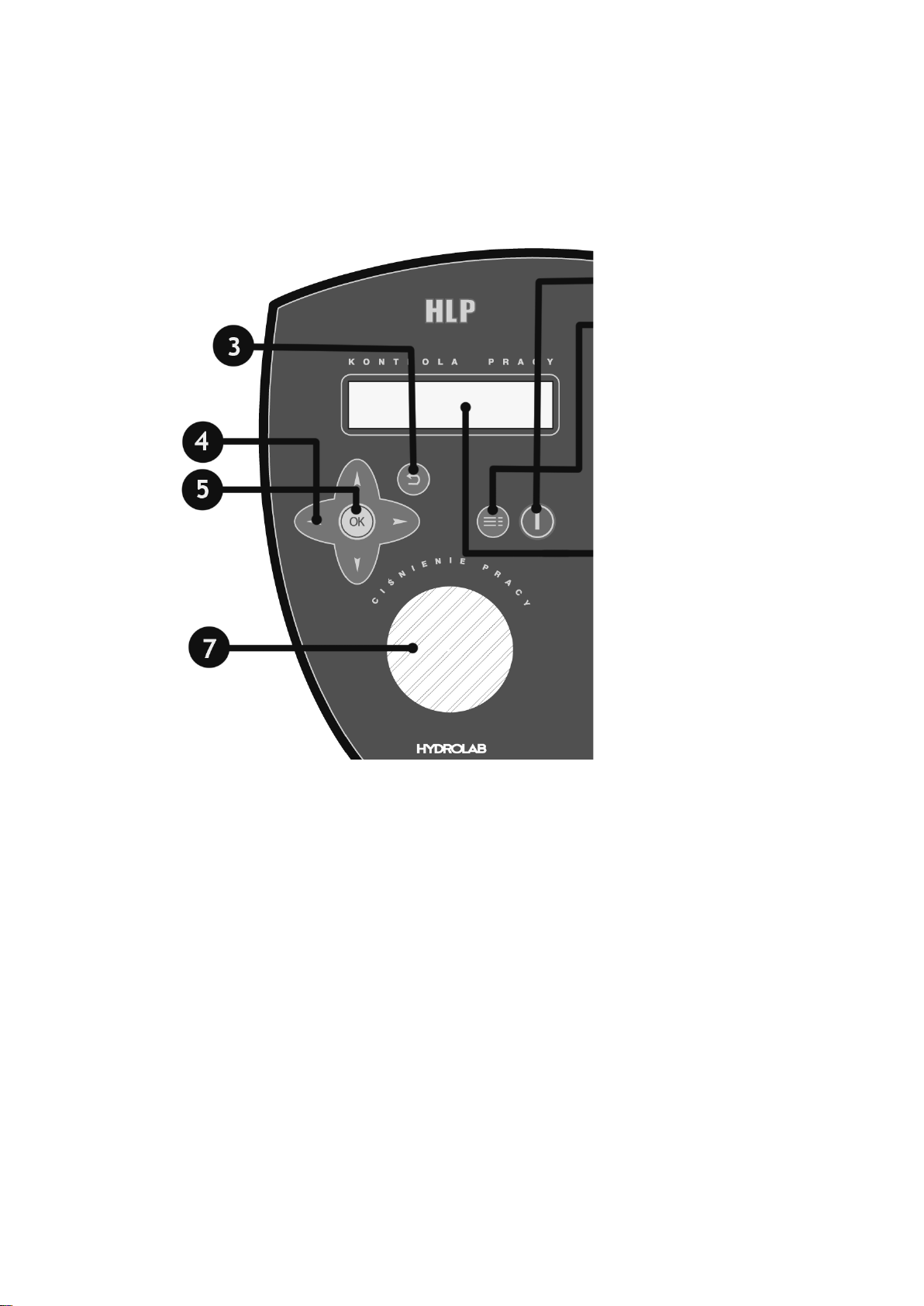
3. Technical specification
The device is equipped with:
sediment prefilter 5 μm
module A (sediment-carbon)
ion exchange module H6
conductometer measuring demineralized water conductivity, equipped with an
alarm informing about necessity to replace ion exchange resins
manometer measuring feed water parameters
control system
…………………………………
…………………………………
…………………………………
3.1. Materials
All used materials are inert with water:
- all wires are made of polyurethane
- connectors and fittings – polyethylene or polyvinylchloride,
- ion exchange column – polypropylene,
- distributors and column filtration nozzles – polyethylene,
- conductometric probe – polyethylene and stainless steel
4. Installation
GENERAL INFORMATION BEFORE INSTALLATION
• Best results are achieved when the demineralizer is fed by softened water.
• Feed water should match the requirements defined in 1.3 (temperature, pressure,
etc.)
• Performing quality analysis of feed water allows for matching a right initial
purification.
Cartidges should be replaced with a frequency that is recommended further in this
manual.
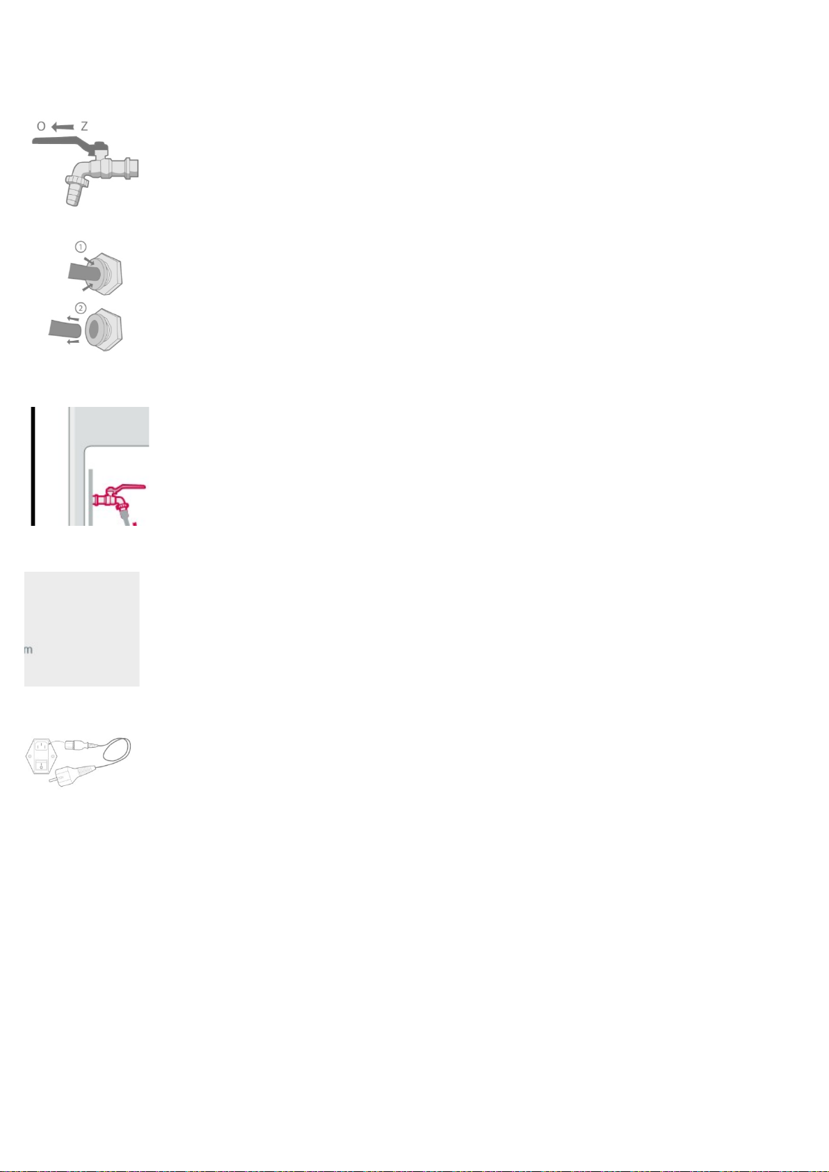
4.1 Demineralizer installation
Remember to place the fillers in the wires (connected by the caps). In case of quick
couplings, just plug in the wire to the connector (make sure it is evenly cut).
Step 1
Put the device in a suitable place.

7
Step 2
Supply valve installation.
Due to the different local conditions, supply valve given by the producer has two
reductions: ½” and ¾”. You should make sure, that the main water supply valve is closed
and the water in the supply pipe is not under pressure. You should make sure, that the
demineralizer is supplied with cold water.
Step 3
Connections for the tank, demi water faucet, feed water and outflow are located on the
side of the device: „FEED WATER”, „TAP WATER”, „DRAIN”, „TANK”.
They are closed by wires. To remove them, hold the black quick coupling ring and pull out
the wire.
Step 4
Sediment prefilter 5 µm should be installed between the supply connector and the
demineralizer („FEED WATER”).
Step 5
Connect the demi water faucet with a proper connector on the demineralizer („TAP
WATER”).
Step 6
Connect the power supply cable to the power socket and plug it into the device's power
supply socket.
5. Turning on the demineralizer
Step 1
• Check every connection.
Step 2
• Demineralizer's sealing pressure test.
• Open the feed water valve.
• Open „TAP WATER”, when water appears – close it.
• Check the demineralizer's sealing.

8
5.1 Turn off the demineralizer
Procedures that shoud be performed when turning off the device:
• Disconnect the device from the power supply.
• Close the feed water valve.
5.2 Demineralizer operation
Basic demineralizer works under the tap water pressure. Basic demineralizer is fully
automated. Using the faucet the user can obtain demineralized water of conductivity χ <
1 μS/cm, matching the standards of ISO 3696, ASTM, CLSI for secondo and third purity
class. Demi water faucet contains a spiral wire (2m reach).
6. Monitoring functions
Basic demineralizer has a built-in control system informing about the necessity to replace
the filtration cartridges. It is possible to connect it with a computer, allowing for an
individual set of alarm levels and service frequency. The device is also equipped with a
conductometer measuring conduction and temperature of the purified water.
6.1 Control and measurement panel
The device is equipped with a microprocessor control and measurement system, that
contains:
display screen LCD 2x16 characters,
conductometer measuring conductivity and temperature of purified water,
clock displaying date and time,
alarm informing about necessity to replace the initial filters:
„Replace A module”
alarm informing about necessity to replace the ion exchange module:
„Replace H6module”
built-in RS 232 connector intended for communication with PC, allowing
individual adjustment of service frequency and alarm levels

9
6.2 Protection functions
LEGEND:
1. TURN ON/TURN OFF
2. ENTER MENU
3. RETURN TO MENU
4. CURSORS
5. CONFIRM/SAVE
6. DISPLAY SCREEN
7. MANOMETER

10
1. Turn on/Turn off (1)
Device name/Date/Time
Conductivity/Temperature
2. Enter menu (2)
Select parameter
Module A replacement deadline*
OK (5)
Module A replacement deadline preview
Down: Module working time
If alarm is present you can see „Replace A module” communicate.
Return to menu (3)
Down: Purified water conductivity alarm
OK (5)
Individual adjustment of conductivity parameters
If alarm is present you can see „Replace H6module” communicate
depending on your device type.
Return to menu (3)
Down: Sound on/off
OK (5)
Select: >YES <NO
Return to menu (3)
Down: Set date and time
Module A date
->Period:06 mths
Module A date
2014.03.15
Select parameter
->Module A date
Alert sound
-> YES
Select parameter
->Alert sound
Conduct alert.
G=020 uS
Select parameter
->Conduct. alert

11
OK (5)
Edit and set date and time using cursors (4)
Return to menu (3)
Down: service contact
OK (5)
Phone number, authorized service e-mail
7. Maintenance
Demineralizer maintenance procedure is to replace the supplies with a proper
frequency.
These are:
• initial filters: prefilter 5 μm, module A (sediment-carbon)
• ion exchange module – module H6.
7.1 Initial filters replacement
Initial filters: prefilter 5 μm, module A. The replacement frequency depents on the
amount and quality of filtered water. Because of hygenic reasons, the control should not
be performed not rarelier than every six months. This procedure may be performed by
the user. System informs the user about necessity to replace the initial filters on the
display screen. A „Replace A module” monit appears, and the system triggers a sound
alarm aswell.
Step 1
Turn off the device and close the feed water valve.
Step 2
5 μm prefilter cartridge replacement
• Twist off the filter body by hand or using a key
• In the body there is a gasket – don't lose it.
• Pull out the filtration cartridge and replace it by a new one
• Close the filter body with the filter head, until a slight resistance, and then close it to
the end
Call …………………….
www……………………
Select parameter
->Service inform.
Set clock
2015.03.22 09:30
Select parameter
->Set clock

12
Step 3
Module A replacement
• Open the back cover
• Plug out the exhausted module A.
• Connect a new module, check the flow directions
• Close the back cover
Step 4
• Open the feed water valve
• Check if there are no leakages
• Reset the alarm:
Select parameter (2)
Initial filters replacement deadline
OK (5)
OK (5)
Choose YES using left/right arrows (4) and then press OK (5)
Return to menu (3)
To change the alarm period – press OK (5) and change it using cursors Up/Down (4) and
then again „ok” (5).
Return to menu (3)
7.2 Ion exchange filter replacement
The replacement procedure should be performed, when the purified water conductivity
rises above 20 μS/cm. The system informs the user about the necessity to replace these
filters. On the display screen a „Replace H7module” monit appears, and the system
triggers a sound alarm as well.
Step 1
• Turn off the device and close the feed water valve.
Step 2
H6 module replacement:
• Open the back cover.
• Disconnect the exhausted H6 module.
• Connect a new filter, check the flow directions.
• Close the back cover.
Are You sure??
-> YES
Module A date
->Reset
Select parameter
->Module A date

13
Step 3
• Check if there are no leakages.
Step 4
The message „Replace H6module” disappears automatically, when the purified water
conductivity goes below 20µS/cm.
WARNING:
After the resin replacement, the first 10 dm3 of purified water should be poured out to
rinse the systems' connections, because it does not match the required parameters.
8. OSH
You particullary should not:
touch the switches with wet hands,
touch the pressure wires with sharp tools
9. Demineralizer malfunctions
Some malfunctions occur due to not performing simple maintenance procedures or
oversights and can easily be removed without calling for an authorized service.
Unjustified calls will be charged, it applies also to the warranty period.
WARNING:
Don't attempt to repair the device by yourself. The repairs performed by unauthorized
persons may cause serious damage and be dangerous to the user.

14
10. Service book
R - repair, M - maintenance, P - review
date N/K/P procedures made by receiver

15

16
Table of contents