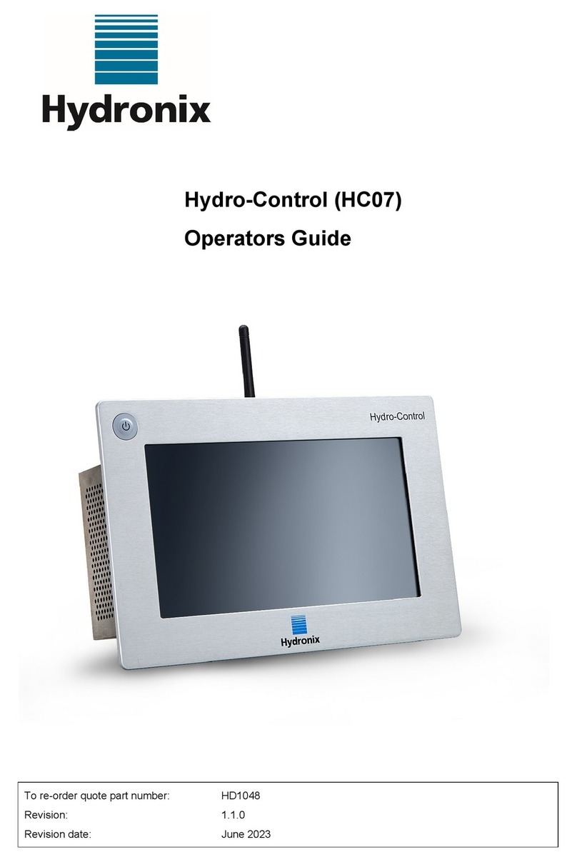
Hydronix Hydro-Control HC07 User manual

Hydro-Control (HC07)
Installation Guide
To re-order quote part number:
Revision:
Revision date:
HD1074
1.2.0
July 2023

2 Hydro-Control (HC07) Installation Guide HD1074 Rev 1.2.0
Copyright
Neither the whole or any part of the information contained in nor the product described in this documentation may
be adapted or reproduced in any material form except with the prior written approval of Hydronix Limited,
hereinafter referred to as Hydronix.
© 2023
Hydronix Limited
Units 11-12 Henley Business Park
Pirbright Road, Normandy
Guildford
Surrey
GU3 2DX
United Kingdom
Company Number: 01609365 | VAT Number: GB384155148
All rights reserved
CUSTOMER RESPONSIBILITY
The customer in applying the product described in this documentation accepts that the product is a
programmable electronic system which is inherently complex and which may not be completely free of errors. In
doing so the customer therefore undertakes responsibility to ensure that the product is properly installed
commissioned operated and maintained by competent and suitably trained persons and in accordance with any
instructions or safety precautions made available or good engineering practice and to thoroughly verify the use of
the product in the particular application.
ERRORS IN DOCUMENTATION
The product described in this documentation is subject to continuous development and improvement. All
information of a technical nature and particulars of the product and its use including the information and
particulars contained in this documentation are given by Hydronix in good faith.
Hydronix welcomes comments and suggestions relating to the product and this documentation
ACKNOWLEDGEMENTS
Hydronix, Hydro-Probe, Hydro-Mix, Hydro-Skid, Hydro-View and Hydro-Control are Registered Trade Marks of
Hydronix Limited
CUSTOMER FEEDBACK
Hydronix is continually looking to improve not only its products but also the services that we offer to our
customers. If you have any suggestions about how we can do this or if you have any other feedback that would
be helpful please complete our short form at www.hydronix.com/contact/hydronix_feedback.php.
If your feedback is concerning an Atex certified product or associated service it would be very helpful for you to
give us your contact details and the model number and serial number of the product if possible. This will enable
us to contact you with any relevant safety advice should this be necessary. It is not obligatory to leave your
contact details and any information will be treated as confidential.

Hydro-Control (HC07) Installation Guide HD1074 Rev 1.2.0 3
Hydronix Offices
UK Head Office
Address: Units 11 & 12 Henley Business Park
Pirbright Road
Normandy
Guildford
Surrey
GU3 2DX
United Kingdom
Tel: +44 1483 468900
Website: www.hydronix.com
North American Office
Covers North and South America, US territories, Spain and Portugal
Address: 692 West Conway Road
Suite 24, Harbor Springs
MI 47940
USA
Tel: +1 888 887 4884 (Toll Free)
+1 231 439 5000
Fax: +1 888 887 4822 (Toll Free)
+1 231 439 5001
European Office
Covers Central Europe, Russia and South Africa
Tel: +49 2563 4858
Fax: +49 2563 5016
French Office
Tel: +33 652 04 89 04

4 Hydro-Control (HC07) Installation Guide HD1074 Rev 1.2.0

Hydro-Control (HC07) Installation Guide HD1074 Rev 1.2.0 5
Revision history
Revision No
Software
Version
Date
Description of Change
1.0.0
May 2023
First Release
1.1.0
June 2023
(HC06) to (HC07) adaptor plate information
added
1.2.0
July 2023
Referenced documents list and mounting
brackets info updated

6 Hydro-Control (HC07) Installation Guide HD1074 Rev 1.2.0

Hydro-Control (HC07) Installation Guide HD1074 Rev 1.2.0 7
Table of Contents
Chapter 1 Safety Information................................................................................................................13
1Introduction.................................................................................................................................13
2Classifications and Markings......................................................................................................14
3Specifications and Ratings.........................................................................................................14
Chapter 2 Introduction...........................................................................................................................17
1Introduction to the Hydro-Control...............................................................................................17
2Packaging and box content........................................................................................................18
Chapter 3 Mechanical Installation.........................................................................................................21
1Weight and Dimensions .............................................................................................................21
2Mounting and installation ...........................................................................................................22
Chapter 4 Electrical Installation.............................................................................................................25
1Connecting the HC07 to an existing HC06 installation ..............................................................25
2Installations using AC I/O...........................................................................................................27
3Connector pin assignments........................................................................................................28
4Power Supply.............................................................................................................................30
5Communications.........................................................................................................................30
6Expansion Board (Hydronix Part Number 7010)........................................................................31
7I/O Wiring Diagrams...................................................................................................................32
8Cables ........................................................................................................................................37
9USB Ports...................................................................................................................................37
Chapter 5 Commissioning.....................................................................................................................39
1Navigation ..................................................................................................................................39
2Basic Tests and Configuration ...................................................................................................41
3System Parameters....................................................................................................................46
4Sensor Overview........................................................................................................................53
5Settings ......................................................................................................................................60
6Recipe Parameters.....................................................................................................................66
Chapter 6 System Design.....................................................................................................................75
1Water Valves..............................................................................................................................75
2Flow Measurement.....................................................................................................................77
3Retrofitting Systems...................................................................................................................78
4Mix Cycle Design........................................................................................................................82
Chapter 7 RS232 Interface ...................................................................................................................89
1Port Settings...............................................................................................................................89
2RS232 Protocol Configuration....................................................................................................89
3RS232 Commands HC05/HC06/HC07 Formats........................................................................90
Chapter 8 Remote Support.................................................................................................................105
1Accessing the Hydro-Control remotely.....................................................................................105
Chapter 9 Backup, Restore and Upgrade...........................................................................................107
1USB Ports.................................................................................................................................107
2The Backing up, Restoring and Upgrading functions...............................................................107
Appendix A System Parameters Record ............................................................................................109
Appendix B Diagnostics ......................................................................................................................111
Appendix C Glossary ..........................................................................................................................113
Appendix D Document Cross Reference............................................................................................115

8 Hydro-Control (HC07) Installation Guide HD1074 Rev 1.2.0

Hydro-Control (HC07) Installation Guide HD1074 Rev 1.2.0 9
Table of Figures
Figure 1: The Hydro-Control screen .....................................................................................................17
Figure 2: Example implementation of Hydro-Control............................................................................17
Figure 3: The Hydro-Control .................................................................................................................18
Figure 4: Rear view of the Hydro-Control .............................................................................................21
Figure 5: Mounting brackets..................................................................................................................22
Figure 6: Panel cut-out for the Hydro-Control.......................................................................................22
Figure 7: Aligning (HC06) and (HC07) panel cutouts ...........................................................................23
Figure 8: HC06 wiring conflict warning label.........................................................................................25
Figure 9: HC06 vs HC07 –10-pin connector pinout differences ..........................................................25
Figure 10: HC06 wiring to HC07 adaptor loom.....................................................................................26
Figure 11: Location of the Protective Earth...........................................................................................26
Figure 12: The rear of the Hydro-Control –connector labels ...............................................................27
Figure 13: The base of the Hydro-Control showing electrical connectors............................................27
Figure 14: Digital Input Wiring Diagram................................................................................................32
Figure 15: Digital Output Wiring Diagram .............................................................................................32
Figure 16: Connecting a DC input signal to an AC input card ..............................................................33
Figure 17: Connecting an AC input signal to a DC input card..............................................................33
Figure 18: Activating an AC device using DC I/O card output..............................................................34
Figure 19: Activating a DC device using AC I/O card output...............................................................34
Figure 20: Analogue Input Current Loop Wiring Diagram.....................................................................34
Figure 21: Connecting a loop-powered device .....................................................................................35
Figure 22: Connecting the current loop of an externally powered device.............................................35
Figure 23: Connecting a voltage signal to the Analogue Input .............................................................35
Figure 24: Analogue Output Wiring Diagram........................................................................................36
Figure 25: The recipe selection input wiring .........................................................................................36
Figure 26: Main menu bar.....................................................................................................................39
Figure 27: I/O test page ........................................................................................................................42
Figure 28: Analogue inputs configuration .............................................................................................43
Figure 29: I/O settings page..................................................................................................................43
Figure 30: Remote recipe modes..........................................................................................................44
Figure 31: RS232 communication mode selection ...............................................................................44
Figure 32: Admix output configuration ..................................................................................................45
Figure 33: Water Tank Full input configuration.....................................................................................45
Figure 34: Water addition modes..........................................................................................................46
Figure 35: Water setup page - metered................................................................................................46
Figure 36: Water setup page –timed....................................................................................................47
Figure 37: Water setup page - weighed................................................................................................47
Figure 38: Auto control page.................................................................................................................49
Figure 39: System Parameters - Auto-Track ........................................................................................50

10 Hydro-Control (HC07) Installation Guide HD1074 Rev 1.2.0
Figure 40: Archiving page.....................................................................................................................51
Figure 41: The weighed water setup page............................................................................................52
Figure 42: Sensor overview screen navigation.....................................................................................53
Figure 43: The sensor details page ......................................................................................................54
Figure 44: Digital I/O page ....................................................................................................................55
Figure 45: Analogues page...................................................................................................................55
Figure 46: Signal Processing page.......................................................................................................56
Figure 47: Averaging and Auto-Track...................................................................................................56
Figure 48: Temperature compensation page........................................................................................57
Figure 49: Material Calibration page.....................................................................................................57
Figure 50: Factory settings page ..........................................................................................................58
Figure 51: Live Data diagnostics page..................................................................................................59
Figure 52: Hardware Test diagnostics page .........................................................................................59
Figure 53: Settings –Defaults page......................................................................................................60
Figure 54: Settings - Date/Time page...................................................................................................61
Figure 55: Settings - selecting date format ...........................................................................................61
Figure 56: Settings - selecting the time zone........................................................................................62
Figure 57: Settings - selecting the day and time...................................................................................63
Figure 58: Settings - selecting the month .............................................................................................63
Figure 59: Settings –selecting the year................................................................................................64
Figure 60: Settings –Measures page...................................................................................................64
Figure 61: Settings –Brightness page..................................................................................................65
Figure 62: Editing a Recipe –Recipe Details .......................................................................................66
Figure 63: Editing Recipe - Water Addition...........................................................................................67
Figure 64: Editing Recipe - Material Addition and Mixing Times..........................................................68
Figure 65: Editing Recipe - Mix Control................................................................................................70
Figure 66: Editing Recipe - local Auto-Track settings...........................................................................71
Figure 67: Editing Recipe - Calculation Mode Settings ........................................................................72
Figure 68: Editing Recipe - Auto Mode Settings...................................................................................73
Figure 69: Editing Recipe - Temperature Correction Settings..............................................................74
Figure 70: Typical water valve set-up ...................................................................................................75
Figure 71: System Block Diagram ........................................................................................................78
Figure 72: Example Wiring Schematic For Manual Plant Operation ....................................................79
Figure 73: System Interconnections .....................................................................................................81
Figure 74: The Complete Mix Cycle......................................................................................................82
Figure 75: The Mix cycle showing the I/O status..................................................................................83
Figure 76: The Admix output signal during a normal mix cycle............................................................84
Figure 77: The Admix output signal during a 2-step mix cycle.............................................................85
Figure 78: The mix trace showing Auto-Track settings.........................................................................86
Figure 79: Auto-Track parameter example for the Dry Mix phase........................................................86
Figure 80: RS232 communication options............................................................................................89

12 Hydro-Control (HC07) Installation Guide HD1074 Rev 1.2.0

Hydro-Control (HC07) Installation Guide HD1074 Rev 1.2.0 13
Chapter 1 Safety Information
1 Introduction
1.1 Purpose and scope
This manual is not a user guide. It is designed as a reference guide for engineers designing,
installing, or commissioning a Hydro-Control (HC07) system. Before installing this device, the
personnel involved must read the Safety Information (HD1100).
This manual complements the Operators Guide (HD1048), which details how to set up and
calibrate recipes in the Hydro-Control. It is advisable to read the Operators Guide before
reading this manual to understand the choices of operation and consequent design
requirements.
The manual is divided into three sections covering the mechanical installation, the electrical
installation, and the commissioning of the unit.
Outside the scope of this guide, but covered by separate documentation is:
Warning
Document ref. No.
Document name
HD1061
HC07 Fan replacement guide
HD1087
HC07 Battery replacement instructions
EN0111
HC07 AC IO Board Fuse Replacement Guide
EN0112
HC07 IO Board Replacement Guide
All above mentioned documents are available on request or on www.Hydronix.com website.
1.2 Responsibilities
The safety of any system incorporating the equipment described in this documentation is the
responsibility of the assembler of the system.
Read the safety information guide before attempting to install or use the device. The device
must only be used in accordance with the manufacturer's specified intended use.
The products covered by this document must be installed per the manufacturer's instructions
and used only within the conditions defined in Section 5 of the Safety Information (HD1100).
All installation work must comply with and meet the relevant local standards of electrical
installations. The safety of any system incorporating Hydro-Control is the responsibility of the
assembler of the system. If Hydro-Control is used in a manner not specified, the protection
provided by this equipment may be impaired.

Chapter 1 Safety Information
14 Hydro-Control (HC07) Installation Guide HD1074 Rev 1.2.0
2 Classifications and Markings
The following approvals and certifications are provided: The Hydro-Control (HC07) has been
designed to meet the requirements of UL/IEC 61010-1 Edition 3.1.
This device complies with part 15 of the FCC Rules. Operation is subject to the following
conditions: (1) This device may not cause harmful interference, and (2) this device must accept
any interference received, including interference that may cause undesired operation.
A full declaration of conformity and other relevant
documentation is available by following this QR code.
3 Specifications and Ratings
For more information on specifications and ratings, refer to chapter 1, section 5 of HD1100
Hydro-Control (HC07) Safety Information.
3.1 Intended use
Hydro-Control (HC07) is intended to work with the Hydronix range of sensors to monitor the
moisture level in a process and send signals to adjust the water flow into the process using
water valves.
3.2 Lightning Strikes
Consideration should be given to protecting the installation from damage caused by lightning
and similar electrical disturbances.
Many installations will be in situations that are particularly prone to damage by lightning, for
example:
•Tropical Regions.
•Long cable runs between the sensor and the control panel.
•Tall, electrically conductive constructions (e.g. aggregate bins).
Although the Hydro-Control is fitted with isolation on the sensor input, this will not prevent
damage in all cases. Precautions should still be taken to avoid lightning damage in areas with
a known risk.
Installing suitable lightning barriers to all conductors in the sensor extension cable is
recommended. Ideally, these would be fitted at both ends of this cable to protect the sensor,
the Hydro-Control and any other equipment.
Installing the equipment using screened cables is recommended to the specification defined
in Chapter 4 Section 8.

Chapter 1 Introduction
Hydro-Control (HC07) Installation Guide HD1074 Rev 1.2.0 15
3.3 Cleaning
The front panel of the Hydro-Control should be cleaned with a soft cloth. Abrasive materials
and liquids must not be used.
3.4 Clearance Requirements
It is important to ensure that the Hydro-Control has adequate clearance for ventilation and
access. The side vents and fan vents on the back of the unit should not be restricted. The
minimum clearance for the back and sides of the enclosure is 60mm.

Hydro-Control (HC07) Installation Guide HD1074 Rev 1.2.0 17
Chapter 2 Introduction
Figure 1: The Hydro-Control screen
1 Introduction to the Hydro-Control
The Hydro-Control (HC07) is a touch-screen computer based on a Linux operating system. It
has been designed to work with the Hydronix range of sensors. The unit monitors the moisture
level in a process (usually in a mixer) and sends signals to adjust the water flow into the process
using water valves.
The moisture level during the process cycle is displayed on the Overview Screen, and there are
intuitive and easy-to-use graphical tools for setting up the recipes in the system.
Communication with external systems can be implemented using either the built-in RS232 serial
port or the optional Expansion Board. The Expansion Board also provides two analogue inputs
and two analogue outputs.
Coarse Water (switches on the coarse valve), Fine Water (switches on the fine valve), Admin, Pre-Wet Done, Mix Complete, Alarm, Water Tank Fill
Digital Outputs:
Digital Inputs:
Start/Resume, Cement In, Pause/Reset, Water Meter Pulse Input, Water Tank Full, Optional 8 inputs for recipe selection
Batch Controller
Hydro-Control
Digital Inputs
Digital Outputs
RS232 / Ethernet Recipe Selection (or by digital I/O)
RS485 Hydro-Mix
or
Hydro-Probe Orbiter
sensor
Counts Litres/Gallons
Fine
On/Off
Coarse
On/Off
Water Meter
Figure 2: Example implementation of Hydro-Control

Chapter 2 Introduction
18 Hydro-Control (HC07) Installation Guide HD1074 Rev 1.2.0
2 Packaging and box content
Figure 3: The Hydro-Control
Standard Contents:
1 x Hydro-Control (HC07) unit
1 x Antenna Kit
2 x Top/Bottom fixing brackets
2 x Side fixing brackets
1 x QR code label
1 x Declaration of Conformity
1 x Safety Information (HD1100)
Additional Contents (If Expansion Board has been factory fitted):
1 x 9 Way Connector for Analogue Inputs/Outputs
1 x 9 Way Connector for Recipe Selection Inputs

Introduction Chapter 2
Hydro-Control (HC07) Installation Guide HD1074 Rev 1.2.0 19
Accessories:
Part No. Description
0117 Power Supply - 24V DC, 120W to power up to 16 sensors
7010 Hydro-Control (HC07) Expansion board for retrofit*
7025 Hydro-Control (HC07) System Card
0175 Panel Mount USB Socket
7010 Hydro-Control (HC07) Expansion board for retrofit
7025 Hydro-Control (HC07) System Card
7030 Hydro-Control (HC07) Replacement Fan
7035 Hydro-Control (HC07) Antenna Kit
7100 Hydro-Control (HC07) Wall Mount Enclosure (IP66 / NEMA4)
7200 Hydro-Control (HC07) Control Cabinet**
7050 Hydro-Control (HC06) to (HC07) adapter plate
7060 Hydro-Control (HC06) to (HC07) adapter cable
*required for weighed water, digital recipe selection and Thermo-Tuff temperature input
** Pre-wired for easy connection to field wiring
Other manuals for Hydro-Control HC07
1
Table of contents
Other Hydronix Control System manuals