1
Hydro-Quip 8000 Series Solid-State Systems were designed for indoor or outdoor installations.
This equipment may be used for in-ground as well as aboveground spas.
INSTALLATION CONSIDERATIONS
lThe Equipment System must be installed on a firm, level surface
(ie: concrete pad)
lThe area where the system is installed must have adequate
drainage to prevent flooding of the equipment under all
circumstances.
lFor performance reasons locate the system as close to the spa as
practical. (Consult local codes for minimum distance between
equipment and spa)
lProvide adequate access around and above the System for service
and maintenance. Three (3’) of clearance around the equipment is
recommended.
lThe pump(s) provided with the system may or may not be self-
priming. Pumps that are NOT self priming must be installed
BELOW water level or they will not prime.
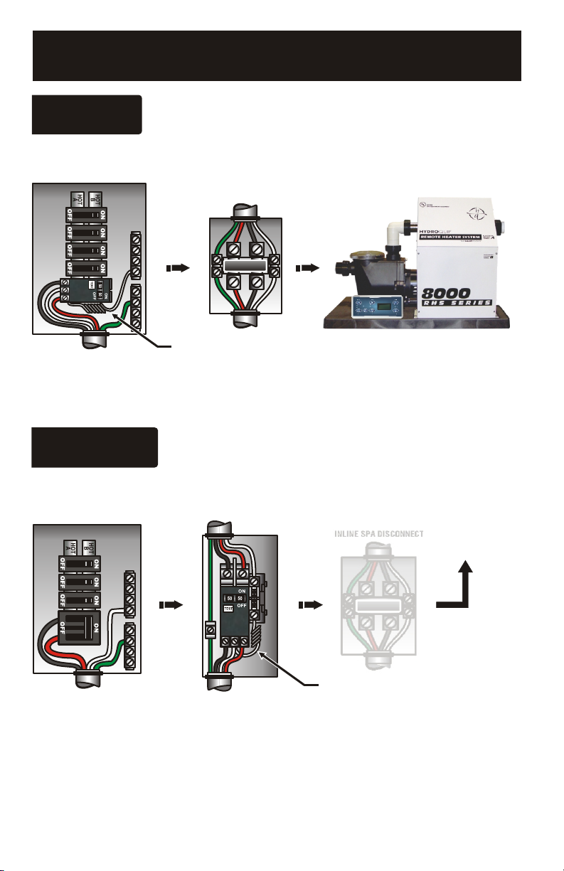
lAll components such as pump, blower, etc are powered from a
multi-position terminal strip inside the upper control box.
Level Surface
Water Level
INSTALLATION INSTRUCTIONS
To assure adequate performance, the spa plumbing must be 1 1/2” minimum. The use of 2” is recommended.
There may be three separate plumbing systems in the spa. Verify the function of each pipe.
1) Suction Side Plumbing - this plumbing will connect to the spa’s skimmer, main drain and suction fittings.
This plumbing connects to the open end of the pump on your Equipment System.
2) Discharge Side Plumbing - this plumbing will go to the spa’s hydrotherapy jet and message fittings. This
plumbing connects to the open end of the heater on your Equipment System.
3) Air Blower Plumbing - this plumbing will go to an air channel under the floor or to an air distribution
manifold of the spa. This plumbing connects only to an air blower.
To allow for safe operation of the spa, the suction fittings connected to the suction opening of the Equipment
System should be listed or approved for the purpose.
ŸEach pump must be provided with two suction fittings. Pump 1 is generally attached to a suction fitting and
a skimmer, while Pump 2 is generally attached to two suction fittings.
After plumbing is complete, secure the Hydro-Quip Equipment System with the appropriate hardware.
Suction Discharge
Page 5 55065-04_97_A
RED AC
WHT AC
J53
J23 J19 J43 J48
K12
U4
J50J52
BLK AC
J66 J65 J63
J64 J42
J54 J56J55
J25J57 J26
TB1
CLASS G
FUSE 30A
CLASS G
FUSE 30A
F6
F7
F4
K4
W1
F2
K7
T1
HTR2 HTR1
FUSE
0.3A 250V
K6
K8
GR
B
W
J79J
J46
J45
J81
12VAC
ADCM
J37J37
J4
J7J7
J74
W8
1
2
3FUSE
3A 250V
TORQUE
RANGE
FOR TB1:
27-30 IN. LBS.
HOT
BLACK
NEUTRAL
WHITE
HOT
RED
Balboa
J11J11 J8J8
BARCODE
GR
B
W
W W J12
J14
W13
W12
K13
W20
W15
BALBOA INSTRUMENTS, INC. MADE IN U.S.A.
EL2000 TC MACH III COPYRIGHT 2005
P/N 22896 REV B
K10
J2
MAIN
PANEL
MAIN
PANEL
MAIN
PANEL
AUX
PANEL
AUX
PANEL
J9
J5
J6
K3
J3
K2
W2
F5
W9 W7
REMOTE
K11
K9
J1
K1
GR
B
W
GR
B
W
GR
B
W
J86
J80
J60J60
J69
J20J1
0
FUSE 10A 250V
J39
J71 J70
J98J98
J89
J91
J17
J15 J13
J83
J22 J24
J82
J36
TST
SENS. A VAC EXT. 2SP PUMP 3 EXT. RLY
AUX. F
J72
CFG
SWITCHBANK A SWITCHBANK B
J90
J977
GR
B
W
J85J85J85
RTC Enabled
5.5 kW
A.V.
Blower
1-Spd P2
Ozone
Circ.Pump
12V Light
Spa
Light
2-Spd P1
Wiring Configuration and DIP Settings
Setup 1 (As Manufactured)
Switchbank A Switchbank B
A2, Low Amp
A5, Degrees F
A6, Short Timeouts
A9/A10,
No Circ Pump
A1, Test Mode OFF
A3, Filter by Time
A4, 12 Hr Time
A7, Cleanup Cycle OFF
A8, 1Hr O3 Supress OFF
A12, Memory Retained
B1, Pump 2 2-Speed
B2, Pump 2 Disabled
B3, Blower Disabled
B4, No Fiber/Wheel
B5, Pump 3 Disabled
B6, Panel Scrunching OFF
100
114
32
SSID #
J37
3
2
1
12 V
Light
J91
RTC
Enabled
(Not Jumpered)
B3, Blower Enabled
B2, Pump 2 Enabled
B1, Pump 2 1-Speed
A11, O3 w/ P1 Low
and P1 is 2-Spd
A2, High Amp
J17
J15
J83
J22
AUX.F
SENS. A
TST
CFG
When the Logic Jumper is not installed on J83 (CFG),
DIP Switch Settings are enabled.
DIP Switches will then operate as shown below.
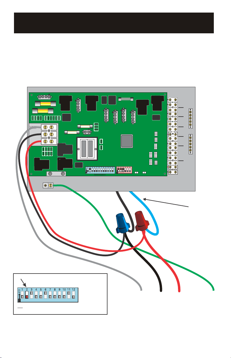
120 Volt Connections
240 Volt Connections
Black AC Jumpers
12 Volt Connections
Relay Control Wires
Wiring Color Key
Typically Line voltage
Typically Line voltage for 2-speed pumps
Neutral (Common)
Ground
Note flat sides in connector
1
2
3
4
Board Connector Key
WARNING: Main Power to system should be turned OFF BEFORE adjusting DIP switches.
WARNING: Persistent Memory (A12) must be RESET to allow new DIP switch settings to take effect. (See Persistent Memory page)
SENS. B
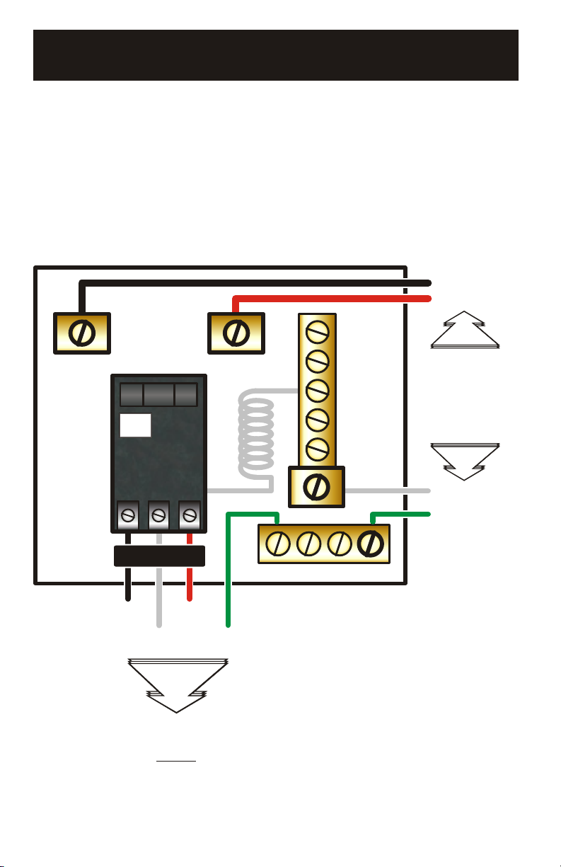
GAS HEATER CONNECTION