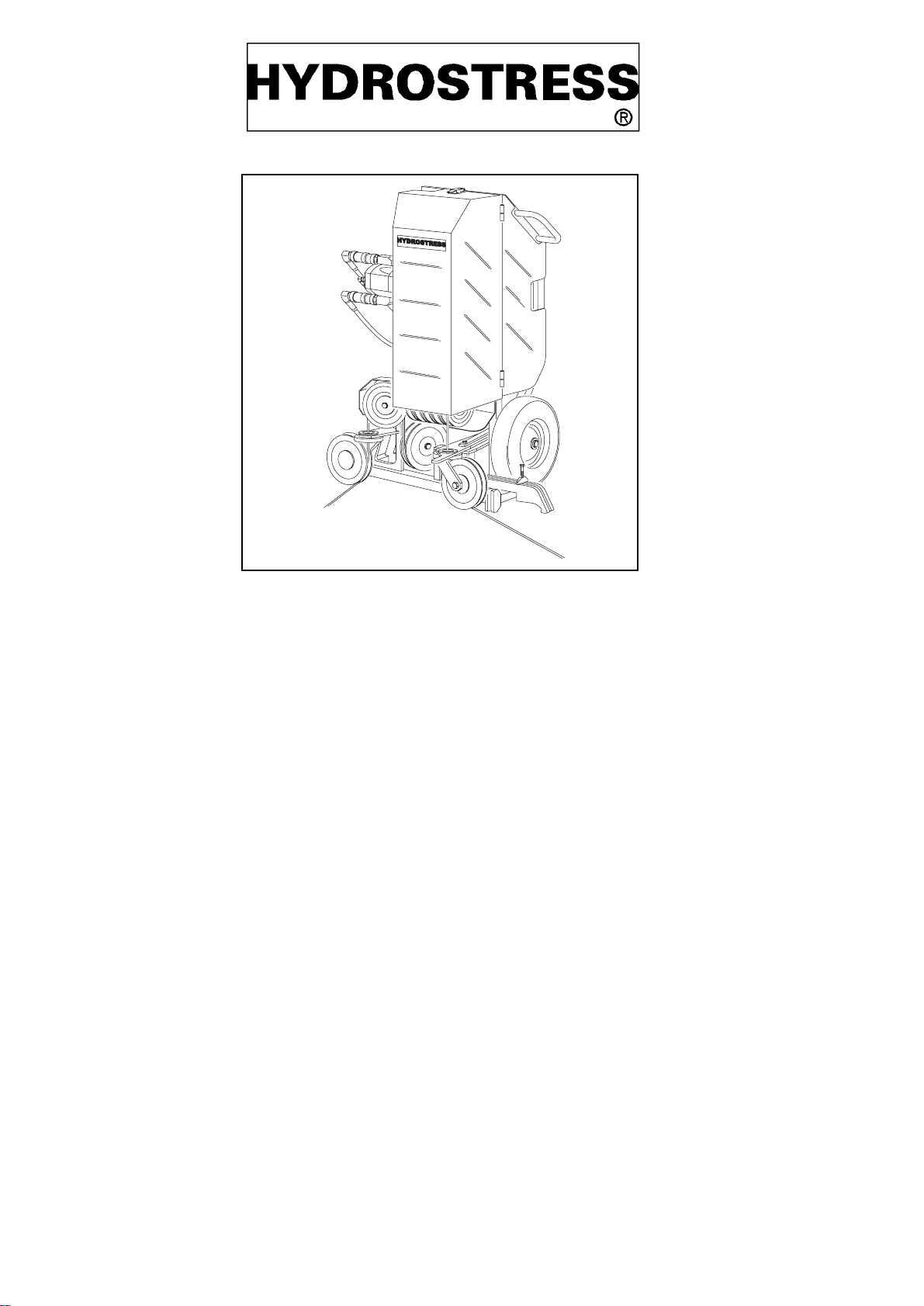
SB Wire Sawing System
SB_0107_e.mif Page 3
7DEOHRIFRQWHQWV
6DIHW\LQVWUXFWLRQV
1.1 Fundamentals 4
1.2 Inherent dangers of wire saws 6
1.3 Intended purpose 7
1.4 Before starting work 8
1.5 After work 8
7HFKQLFDOGDWD
2.1 Possible cutting capacity 9
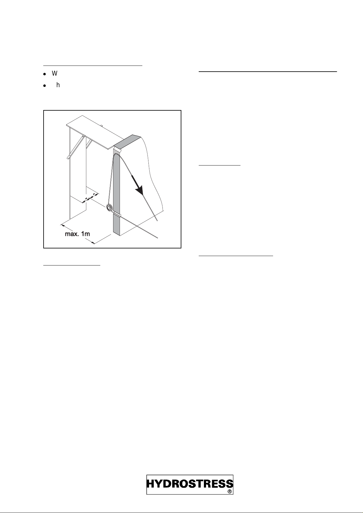
2.2 Dimensions 9
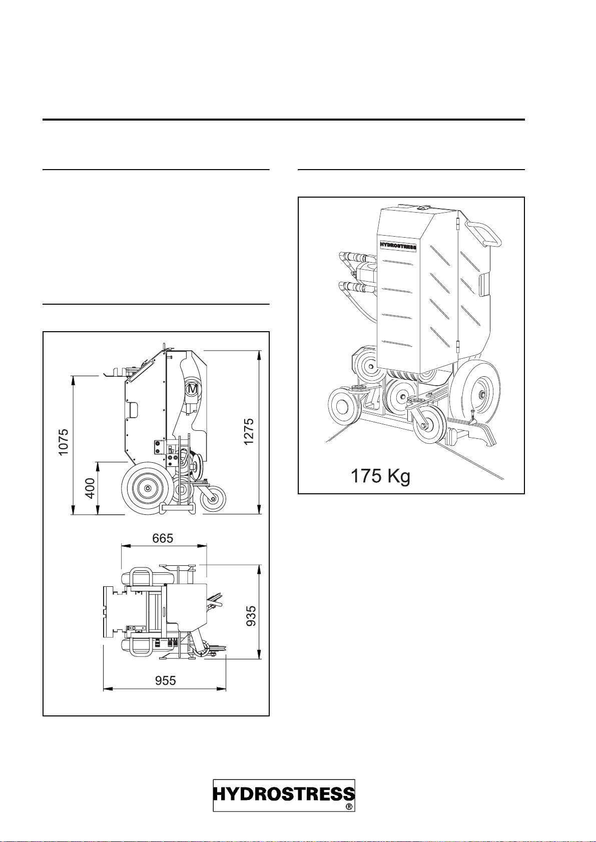
2.3 Weight 9
2.4 Wire drive 10
2.5 Connectable drives 10
2.6 Wire running direction 10
2.7 Wire cutting speed 11
2.8 Wire lengths 12
6DIHDQGHIILFLHQWRSHUDWLRQ
&RQVWUXFWLRQ
&RQWUROHOHPHQWV
:DWHU
$SSOLFDWLRQDODGYLFH
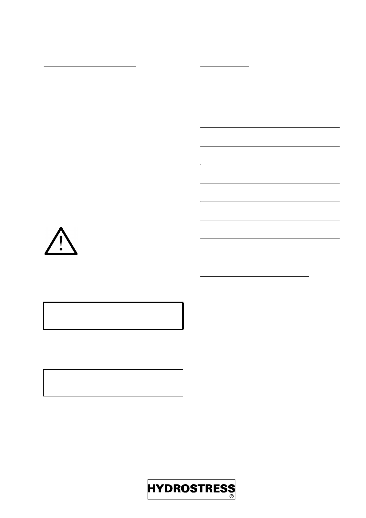
7.1 Setting up the SB 17
7.2 The correct cutting direction 18
7.3 Finish cutting 18
7.4 Flush cutting against a wall 19
7.5 Flush cutting against the floor 19
7.6 End of cut 19
7.7 Establish removal direction 19
7.8 Rounding off the structural body 20
7.9 The cutting sequence 20
&RQQHFWLRQRIK\GUDXOLFVDQGZDWHU
8.1 Example of CR-5 RC 21
7KHGLDPRQGZLUH
9.1 Types of diamond wire 24
9.2 Preparation of wire ends 25
9.3 Avoiding out-of-round wear 25
9.4 Connect wire 30
,QVHUWZLUH
10.1 Insert wire, general. 32
10.2 Insert wire, 1st step 33
10.3 Insert wire, 2nd step 33
10.4 Insert wire, 3rd step 33
10.5 Insert wire, 4th step 33
6WRUHZLUH
11.1 Store wire, 1st step 34
11.2 Store wire, 2nd step 34
11.3 Store wire, 3rd step 34
11.4 Store wire, 4th step 34
5XQXSZLUHVDZ
12.1 Pull wire through by hand 36
12.2 Switch on drive unit 36
12.3 Presetting the feed 36
12.4 Letting the wire run 36
12.5 Operation 37
12.6 Interruption of cut 37
12.7 End of cut 37
12.8 Terminate operation 37
5HFWLI\LQJIDXOWV
0DLQWHQDQFH
14.1 Maintenance table 41
14.2 Repairs 41
7UDQVSRUWSXWWLQJRXWRIRSHUDWLRQ
VWRUDJHDQGGLVSRVDO
15.1 Transport 42
15.2 Putting out of operation, storage 42
15.3 Disposal 42
$FFHVVRULHVVSDUHSDUWVOLVWV
16.1 Accessories delivered together
with the SB 43
16.2 Accessories which can be ordered 43
16.3 Spare parts lists, ordering details 43