KMC Controls KMD-5551E User guide

Applications Guide
KMD-5551E translator
Tier 2
Tier 2
Translator A Translator B
Includes installation, operation, and maintenance instructions
Revision B

Copyrights and trademarks
©2017, KMC Controls, Inc.
NetSensor, WinControl, and the KMC logo are registered trademarks of KMC Controls, Inc.
AppStat, BACstage, FlexStat, FullBAC, KMC Connect, KMC Connect Lite, KMC Converge,
KMC Converge GFX, KMC Conquest, TotalControl, SimplyVAV, and the SimplyVAV logo are
trademarks of KMC Controls, Inc.
Tridium, JACE, Niagara Framework, NiagaraAX, Niagara N4, and Vykon are registered
trademarks of Tridium, Inc.
Workbench, WorkPlaceAX, and AX Supervisor, are trademarks of Tridium Inc.
All rights reserved. No part of this publication may be reproduced, transmitted, transcribed,
stored in a retrieval system, or translated into any language in any form by any means
without the written permission of KMC Controls, Inc.
Printed in U.S.A.
The material in this manual is for information purposes only. The contents and the product it
describes are subject to change without notice. KMC Controls, Inc. makes no
representations or warranties with respect to this manual. In no event shall KMC Controls,
Inc. be liable for any damages, direct or incidental, arising out of or related to the use of this
manual.
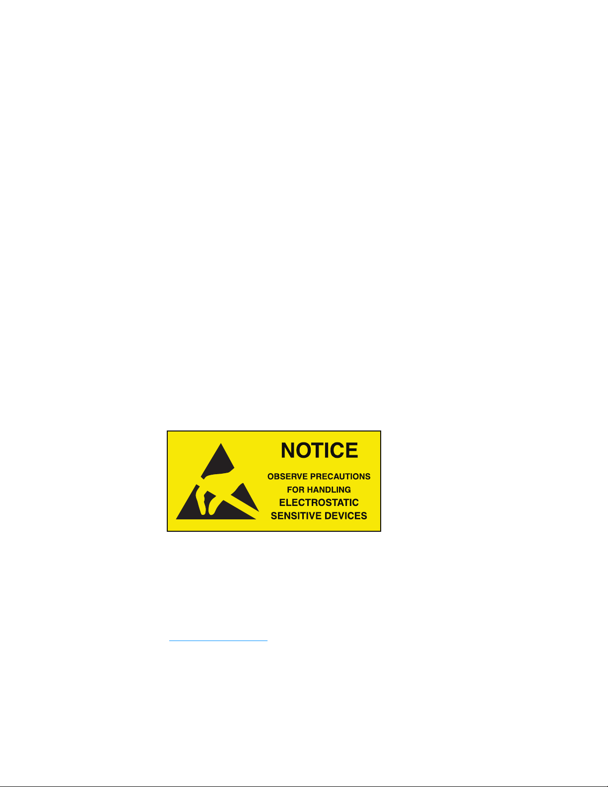
Handling precautions
To prevent damage from electrostatic discharges, take reasonable precautions when
handling, servicing, or installing the router. Discharge accumulated static electricity by
touching your hand to a securely grounded object before working with the router.
KMC Controls, Inc.
19476 Industrial Drive
New Paris, IN 46553
U.S.A.
TEL: 1.574.831.5250
FAX: 1.574.831.5252
info@kmccontrols.com
KMC Controls, Inc.
2 Revision B

C o n t e n t s
Contents 3
Section 1: Introduction 5
Specifications 5
Accessories and replacement parts 8
Mounting the translator 8
Connecting for network routing 9
Tier 2 wiring 10
EOL (End-Of-Line) termination switches 10
Connecting power 10
Single-cable connection 12
Maintenance 13
If you encounter difficulty 13
Section 2: Translation concepts 15
Translation rules 15
KMD to BACnet translation 16
BACnet to KMD translation 16
Applicable controllers 16
Example networks 17
KMD Tier 2 only 17
KMD Tier 1 and a single KMD Tier 2 18
KMD Tier 1 and two KMD Tier 2 networks 19
Section 3: Configuring the KMD-5551E translator 21
Initial setup 21
Set up for configuration 22
Logging in 22
Changing your computer's address 24
Device properties page 27
Time page 28
Security page 29
KMD HPO Override Report page 30
Session timeout 32
Section 4: Setting up translation 33
BACnet IP routing 33
BACnet foreign device routing 34
BACnet Broadcast Management Device routing 36
Network address translation 37
Table 37
BACnet PAD routing 38
Configuring the KMD Virtual Port 39
Main Net (Tier 1) 39
Subnet (Tier 2) 40
KMD Subnet Device Configuration page 40
KMD columns 41
BACnet columns 42
Routing Status page 42
Route Status buttons 43
Route Status list 43
KMD-5551E Translator
Revision B 3

Purging the Route Status list 46
Licensing the translator 46
Purchase a license 46
Download the required module files 47
Discover and add translators to the BACnet network 47
Add the module files to the station 48
Add the translator license to the station 48
Add the translation service palette 49
Discover the KMD devices 50
Adjust the tuning policy 50
Section 5: Advanced features 53
Recovering the network address 53
Updating the firmware 54
Configure from a file 55
Index 57
Contents KMC Controls, Inc.
4 Revision B

Section 1: Introduction
This section provides a description of the KMC Controls KMD-5551E translator. It also
introduces safety information. Review this material before installing or operating the
translator.
The KMC Controls KMD-5551E translator is a BACnet to KMDigital translator. The translator
highlights are:
lTranslates between one KMD Tier 1 controller and one KMD Tier 2 network to a
BACnet virtual network.
lCompatible with NiagaraAX and Niagara 4 Frameworks.
lEasy to install and simple to configure.
lConfigured from internally served web pages.
lInternal network diagnostics and route status reports.
Topics in this section
Specifications 5
Accessories and replacement parts 8
Mounting the translator 8
Connecting for network routing 9
Connecting power 10
Single-cable connection 12
Maintenance 13
If you encounter difficulty 13
Specifications
Specifications are subject to change without notice.
Communication ports
BACnet Ethernet, BACnet IP, KMD Tier 1
10BaseT/100BaseT, RJ–45 connector
KMD Tier 2
One optically isolated Tier 2 port, 9.6–38.4kilobaud
Removable three-screw terminal block, 12–22 AWG wire
Switched end-of-line termination
USB
USB micro B connection for temporary power
KMD-5551E Translator
Revision B 5

Configuration and software
All configuration is through internal browser based configuration pages. Requires HTML5
browser.
BACnet routing
One BACnet IP port that can be set up for any of the following protocols:
lNormal BACnet IP network routing
lBACnet broadcast management device with network and port address translation
lForeign device registration with BACnet broadcast management devices (BBMD)
lPAD (packet assembling/disassembling) routing
One BACnet Ethernet port
Installation
Supply voltage 24 VAC (50/60 Hz) or 24 VDC; –15%, +20%; Class2 only; non-
supervised (all circuits, including supply voltage, are power
limited circuits)
5 volts DC from powered USB connection
Supply source automatically switches to highest available
voltage
8 VA required power
Weight Approximately 5.3 ounces (149 grams)
Case material Green and black flame retardant plastic
Processor and memory
Processor Processor 32-bit ARM® Cortex-M4
Memory Configuration parameters and diagnostics are stored in
nonvolatile memory; auto restart on power failure
Regulatory and agency listings
UL UL 916 Energy Management Equipment
RoHS RoHS compliant (pending)
CE CE compliant
FCC FCC Class A, Part 15, Subpart B and complies with Canadian
ICES-003 Class A
This device complies with part 15 of the FCC Rules. Operation
is subject to the following two conditions: (1) This device may
not cause harmful interference, and (2) this device must accept
any interference received, including interference that may
cause undesired operation.
Environmental limits
Operating Temperature 32 to 120° F (0 to 49° C)
Shipping Temperature -40 to 140° F (–40 to 60° C)
Humidity 0–95% RH, non-condensing
Section 1: Introduction KMC Controls, Inc.
6 Revision B

Timekeeping
The KMD-5551E translator is a BACnet time master device.
Update interval Daily, weekly, or monthly
Time message type UTC, local, or both
Setting time Synchronized to SNTP server, set from computer time, or
manually entered
Niagara compatibility
Compatible with Niagara 3.8 and later. Requires a license and module added to a Niagara
station, typically in a J.A.C.E. controller, on the same BACnet internetwork.
Translation
Translates between one KMD Tier 1 controller, the controllers connected to one KMD Tier
2 network, or both to a BACnet virtual network. Values for KMD input, output, and variable
points are translated between BACnet input, output, and value objects. Translation is
limited to the following properties:
lPoint values and Present values
lManual and Out-of-service status
lDevice, controller, and panel names
lObject and point names, descriptions, and labels
lUnits of measure
Dimensions and mounting
Surface mount or 35 x 7.5 mm DIN rail mounting
5.64 in.
143 mm
1.25 in.
38 mm
6.31 in.
160 mm
6.00 in.
152 mm
Ø .187 in.
4.8 mm
5.50 in.
140 mm
5.95 in.
151 mm
3.16 in.
80 mm
KMD-5551E Translator Section 1: Introduction
Revision B 7

Accessories and replacement parts
The following accessories and replacement parts are available from KMC Controls, Inc.
Power transformer
XEE-6111-50 Transformer, 120-to-24 VAC, 50 VA, single-hub
XEE-6112-50 Transformer, 120-to-24 VAC, 50 VA, dual-hub
Surge suppressors
KMD-5567 EIA-485 surge suppressor for MS/TPor Tier 2 networks
Cables
HPO-5551 Conquest Router Tech Cable Kit–Includes USB, Ethernet, and
MS/TP to NetSensor cables
HSO-9001 Ethernet cable, 50 feet
HSO-9011 Ethernet cable, 50 feet, plenum rated
Replacement parts
HPO-9901 Controller replacement parts kit with terminal blocks and DIN clip
License
DR-KMD-TRANS Niagara license for any KMD-5551E translator discovered by a
station
Mounting the translator
For permanent installations, the translator can be flush mounted or snapped to a 35 x 75 mm
DIN rail. For translator dimensions, see the topic Specifications on page 5.
Surface mounting Extend the mounting tabs away from the translator body and fasten with
screws.
Illustration 1–1 Surface mounting the translator
Extend mounting tabs
6.00 in.
152 mm
DIN rail mounting Mount the DIN rail and then do the following:
1Extend the mounting tabs.
2Place the bottom of the router over the DIN rail.
3Push the mounting tabs back toward the router body to lock it to the rail.
Section 1: Introduction KMC Controls, Inc.
8 Revision B

Connecting for network routing
Connect the KMD-5551E translator to a network router or network switch and, as needed, to
a KMD Tier 2 network. For permanent installations, the router is typically connected to a 24
volt transformer for power.
For installations that include Internet access, install the translator behind a firewall.
Illustration 1–2 Permanent installation
Internet
Firewall Network router
KMD-5551E
24 volts (on end)
Tier 2
See also the following topics:
lMounting the translator on page 8
lConnecting power on page 10
KMD-5551E Translator Section 1: Introduction
Revision B 9

Tier 2 wiring
Use shielded cable and the following principles when connecting the KMD-5551E translator
to a Tier 2 network:
lUse twisted pair, shielded cable with capacitance of no more than 51 picofarads per
foot for all network wiring. Belden cable model #82760 meets the cable requirements.
lConnect the -A terminal in parallel with all other A or -A terminals.
lConnect the -B terminal in parallel with all other B or +B terminals.
lConnect the shields of the cables together at each controller.
lConnect the shield to an earth ground at one end only.
lUse a KMD-5575 repeater if the cable length will exceed 4,000 feet (1,220 meters). Use
no more than seven repeaters per Tier 2 network.
lPlace a KMD-5567 surge suppressor in the cable where it exits a building.
Illustration 1–3 Tier 2 wiring and end-of-line switches
-A +B S
-A +B S
End of segment
Middle of segment
EOL (End-Of-Line) termination switches
The devices on the physical ends of the Tier 2 wiring segment must have end-of-line
termination added for proper network operation.
lIf the translator is at the end of the network segment, set the EOL switch to ON.
lIf the translator is in the middle of the network segment, set the EOL switch to OFF.
Connecting power
Power the KMD-5551E translator from a 24 volt power source, either AC or DC, or from a USB
connection. The translator begins to operate when a power source is applied. Use the
following guidelines when choosing and wiring sources to the translator.
Section 1: Introduction KMC Controls, Inc.
10 Revision B

For USB power Connect the translator to a powered USB port with a USB A to USB micro B
cable. Typically the USB ports on laptop computers can supply power to the router. When
connecting to a USB hub, verify the power specifications of the hub. See the topic
Specifications on page 5.
Illustration 1–4 USB connection
USB power
Note: When using USB connection for power and communications, use the USB cable from the
HPO-5551 Technician's Router Cable Kit. The cable from the kit is specified to supply
enough power for both the USB and the network connection.
To use the USB for power and network communications, see the topic Single-cable
connection on page 12.
For permanent installations, the translator is usually powered from a 24 volt transformer or
DC power supply.
Illustration 1–5 24 volt power connections
24 volts AC 24 volts DC
For 24 volt AC power Connect a 24 volt transformer to the black power terminal block on the
end of the translator.
lConnect the AC phase to the phase terminal .
lConnect the ground side of the transformer to the ground terminal .
lUse a Class2 transformer of the appropriate size to supply power to the translator.
lKMC Controls recommends powering the translator from a dedicated transformer.
lDo not run 24 volt power from within an enclosure to external devices.
KMD-5551E Translator Section 1: Introduction
Revision B 11

For 24 volt DC power Connect a 24 volt power supply to the black power terminal block on
the end of the router.
lConnect the positive terminal (+) to the phase terminal .
lConnect the negative terminal (-) of the power supply to the ground terminal .
lUse a Class2 power supply of the appropriate size to supply power to the translator.
lKMC Controls recommends powering the translator from a dedicated power supply.
lDo not run 24 volt power from within an enclosure to external devices.
Single-cable connection
The single-cable connection method connects the KMD-5551E translator to a computer with
a USB cable that supplies both power and communications. The USB port becomes a virtual
network interface card (NIC) and establishes a network between the computer and the
translator.
Note: Use the USB cable from the HPO-5551 Router Technician's Cable kit for a single cable
connection. This cable meets the specification to supply the power and communications
required by the translator. Other cables may prevent routing on one or more ports.
Illustration 1–6 Single-cable connection
Computer with
browser
To set up a single-cable connection, do the following:
1Plug the USB cable from the HPO-5551 cable kit into the translator.
2Plug the other end of the USB cable into the computer.
Depending on the version of Windows, the first time the translator is plugged into a
computer, Windows will display a message that it is installing a new driver. Click on the
message to see more details. Note the name of the device in the message because
you will need this information in later steps. Allow the installation to finish and then
close the dialog.
3From the Windows Control Panel, click Network and Internet and then Networking
Sharing Center.
4Once the center is open, click Change Adaptor Settings.
5Identify the Local Area Connection that is associated with the translator and click it to
open the connection.
Section 1: Introduction KMC Controls, Inc.
12 Revision B

6In the Local Area Connection status, click Properties.
7When the next dialog opens, choose Internet Protocol Version 4 and then click
Properties.
8In the Properties dialog, select Use the following IPaddress and then enter a unique
IPaddress and subnet mask.
lThe IP address must be unique and be part of the same subnet as the translator’s
address.
lIf the translator is still configured with the default address, use 192.168.1.252.
lSet the subnet mask to 255.255.0.0.
9When finished, click OK to save the work and then close all dialog boxes.
To test the connection, open a browser window and enter the address of the translator.
When the log in page opens, set up the translator as described in the topic Setting up
translation on page 33.
Maintenance
The KMD-5551E translator requires no routine maintenance. If necessary, clean with a damp
cloth and mild soap.
If you encounter difficulty
If you experience difficulty with the KMD-5551E translator, KMC Controls provides the
following assistance.
The KMC Controls web siteNavigate to the support section on the KMC controls web site
for the latest information for KMD-5551E translator and other KMC Controls products.
www.kmccontrols.com
KMC technical supportOur distribution partners have unlimited and free access to our team
of Technical Support representatives. We provide coast-to-coast and toll-free support from
8:00 AM Eastern to 5:00 PM Pacific time.
Toll-Free Technical Support: (866) 303-4562
KMD-5551E Translator Section 1: Introduction
Revision B 13

Section 1: Introduction KMC Controls, Inc.
14 Revision B

Secti on 2: Transl ation concepts
This section explains the basics of translation, shows example networks, and explains the
rules for translation.
The KMD-5551E translator connects between one or more KMDigital controllers and a
BACnet internetwork. The translator polls designated KMDigital controllers and adds them
as BACnet devices to a virtual BACnet network. The BACnet routing within the translator
makes the virtual network and devices available to any other device or operator workstation
on the internetwork. The devices on the virtual network can then be discovered and
manipulated within the Niagara frameworks as standard BACnet devices and objects.
Illustration 2–1 KMD-5551E translator block diagram
Tier 2
BACnet routing
Tier 1
Translation
Translation
A
BACnet virtual
network and
devices
KMD controllers
and networks
B
C
D
E
A
B
C
D
E
Topics in this section
Translation rules 15
Applicable controllers 16
Example networks 17
Translation rules
The KMD-5551E translator supports one Tier 1 controller and the controllers on one Tier 2
network. The Tier 2 network does not have to be connected to the Tier 1 controller.
lKMDigital input, output, and variable points are translated as BACnet input, output, and
value objects.
lDigital KMD points are translated to binary objects.
lAnalog KMD points are translated to analog objects.
lKMD analog input points with Counts selected as units are translated as BACnet
accumulator objects.
lLabels and descriptions in KMD points are translated as BACnet name and description
properties.
At power-up or reset, the translator scans for devices on the designated KMD networks. For
large networks the translator may take up to an hour to discover all devices and objects.
KMD-5551E Translator
Revision B 15

After the initial discovery, the translator automatically scans once an hour for new devices or
changes. To start an immediate rediscovery, see the topic KMD Subnet Device Configuration
page on page 40.
KMD to BACnet translation
lFor KMD output and variable points not set to Manual, the value of the point is
transferred to the Relinquish Default property of a BACnet output or value object.
lFor KMD output and variable points set to Manual, the value of the point is transferred
to Priority 8 in the Priority Array of a BACnet output or value object.
lValues for KMD input points are transferred to the Present Value of a BACnet input
object.
lKMD input points set to Manual status are transferred to a BACnet input object as Out
Of Service.
lWhen reading a property, values may be cached for up to 30 seconds.
BACnet to KMD translation
lChanging the BACnet Present Value property at any priority level transfers directly to
the value of the KMD point and the point is set to Manual.
lChanging an Input Object to Out of Service changes the KMD point to Manual.
lValues are cached for up to 30 seconds.
Applicable controllers
The following controllers are compatible with the KMD-5551E translator.
Tier 1 controllers
lKMD-5210
lKMD-5205
lKMD-5270
Tier 2 controllers
lKMD-5800 series
lKMD-7000 series
lKMD-7300 series
lKMD-7400 series
Tier 2 controllers (obsolete)
lKMD-5500 series
lKMD-6000 series
lKMD-6100 series
lKMD-6300 series
lKMD-6400 series
lKMD-6900 series
Section 2: Translation concepts KMC Controls, Inc.
16 Revision B

Example networks
The following network diagrams are examples of how to connect the KMD-5551E translator
to KMDigital networks. These are conceptual diagrams only. For detailed installation
instructions, see the following topics.
lConnecting for network routing on page 9
lSetting up translation on page 33
KMD Tier 2 only
For networks without a KMD Tier 1 controller, connect a translator directly to the Tier 2
network and to the same local area network to which the JACE is connected. All Tier 2
devices will appear on the same virtual BACnet network.
Illustration 2–2 KMD-5551E translator connected to a Tier 2 network
KMD-5551E Translator Section 2: Translation concepts
Revision B 17

KMD Tier 1 and a single KMD Tier 2
Connect the KMD-5551E translator to the Tier 2 network and to the same local area network
that the Tier 1 and JACE controllers are connected to. The Tier 1 and all Tier 2 controllers will
appear on the same virtual BACnet network.
Illustration 2–3 KMD-5551E translator connected to a Tier 1 controller and a Tier 2 network
Section 2: Translation concepts KMC Controls, Inc.
18 Revision B

KMD Tier 1 and two KMD Tier 2 networks
A KMD-5210 LAN Controller requires two KMD-5551E translators to translate the points in a
LAN Controller and the controllers on both Tier 2 networks to BACnet devices and objects.
lConfigure Translator A for the Tier 1 controller.
lConnect one of the Tier 2 networks to Translator A and configure it.
lConnect and configure Translator B for the second Tier 2 network.
lThe Tier 1 controller and the Tier 2 controllers associated with Translator A will appear
on one BACnet virtual network. The controllers on the Tier 2 network with Translator B
will appear on a second BACnet virtual network.
Illustration 2–4 Two KMD-5551E translators connected to a Tier 1 controller and two Tier 2
networks
Tier 2
Tier 2
Translator A Translator B
KMD-5551E Translator Section 2: Translation concepts
Revision B 19

Section 2: Translation concepts KMC Controls, Inc.
20 Revision B
Table of contents