POWERING UP - FIRST TIME USE - WITHOUT INSULATING TAB
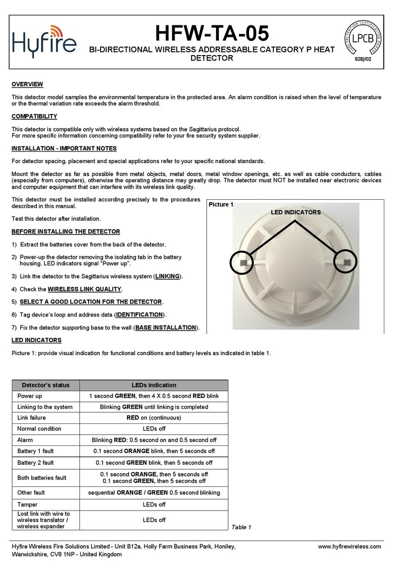
Use this procedure the first time you power up a TAU-TH-01; the detector has not been supplied with the insulating tab.
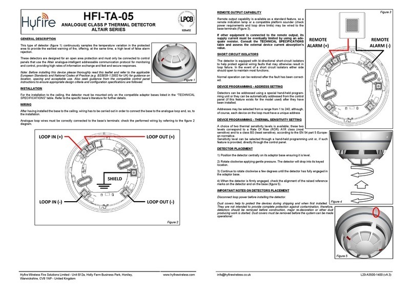
1) Make sure the Link / program switch is set on “ON”.
2) Insert the two supplied batteries into their device’s lodgments.
POWERING UP - DEVICE LINKED TO THE SYSTEM
Use this procedure when a TAU-TH-01 is successfully linked to its Taurus system and you have to extract one or both batteries (e.g.
batteries substitution).
1) Reinsert the battery or both batteries into their lodgments.
If performing a batteries substitution, use two brand new batteries and substitute both of them.
Do not touch the Link / program switch.
POWERING UP - RECOVERY
Use this procedure when you fail to link successfully a TAU-TH-01 or you want to link it again.
1) Move alternatively the Link / program switch 5 times.
2) Set the Link / program switch on “ON”.
3) Insert the two supplied batteries into their device’s lodgments.
LINKING - WAKE-UP - WITHOUT INSULATING TAB
“Wake-up” linking consists in associating one or more child devices to the Taurus system altogether in a single operation.
Wake-up is performed either through the TauREX software or the TAU-TRM-01 / TAU-CEM-01 keyboard-screen interface; it CANNOT be
done through TAU-EXM-01 devices.
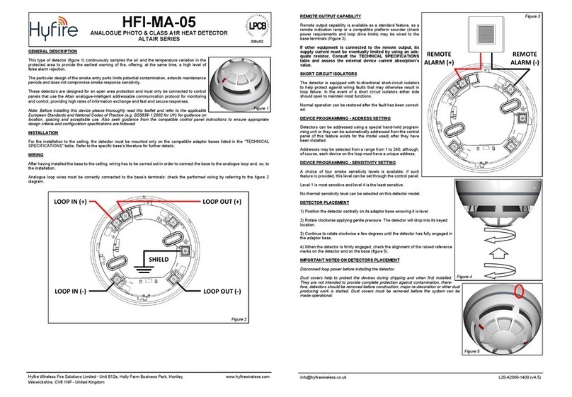
1) Create the “virtual model” of the TAU-TH-01 either on TauREX or on the TAU-TRM-01 / TAU-CEM-01.
2) Power-up the detector (either “first time use” or “recovery”).
3) Set the Link / program switch OPPOSITE to “ON”.
4) Trigger the wake-up procedure either from TauREX or from the TAU-TRM-01 / TAU-CEM-01.
5) Wait the end of the “wake-up” linking procedure.
6) Check on TauREX or from TAU-TRM-01 / TAU-CEM-01 for linking success. Consult their user manual.
LINKING - ONE-BY-ONE - WITHOUT INSULATING TAB
“One-by-one” linking consists in associating one child device at a time to the Taurus system.
This operation is performed either through the TauREX software or the TAU-TRM-01 / TAU-CEM-01 keyboard-screen interface; it CANNOT
be done through TAU-EXM-01 devices.
1) Create the “virtual model” of the child device either on TauREX or on the TAU-TRM-01 / TAU-CEM-01.
2) Trigger the linking procedure either from TauREX or from the TAU-TRM-01 / TAU-CEM-01.
3) Power-up the child device (either “first time use” or “recovery”).
4) Set the child device’s Link / program switch OPPOSITE to “ON”.
5) Wait the end of the “one-by-one” linking procedure.
6) Check on TauREX or from TAU-TRM-01 / TAU-CEM-01 for linking success. Consult their user manual.
TESTING
Magnet test
1) Activate test mode.
2) Apply again the magnet in correspondence of the “magnet test activation area”.
3) LED indicators signal “Alarm activation”.
Heat test
1) Activate test mode.
2) Apply the heat test device to the detector.
3) Wait a few seconds.
4) LED indicators signal “Alarm activation”.
BATTERY FAULTS AND BATTERY SUBSTITUTION PROCEDURE
When one or both batteries are low in charge, a specific fault message is routed to the
control panel. If such event occurs:
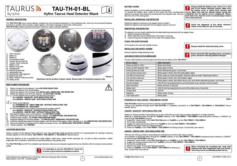
1) Remove the safety screw.
2) Remove the detector from its base.
3) Remove the batteries cover.
4) Extract both batteries.
5) Insert both new batteries into their holders, oriented as per polarity marks.
See POWERING UP - DEVICE LINKED TO THE SYSTEM.
6) Reinstall the batteries cover.
7) Reinstall the detector.
8) Reinstall the safety screw.
Local safety standards may require you
to test these devices on a regular basis.
Use only suitable heat test devices supplied by
approved manufacturers. Follow their specific
use instructions.
Before testing every TAU-TH-01, always
activate test mode. This is done by
holding a suitable magnet in the
“magnet test activation area”. When activated,
LED indicators signal “Test mode active”.
When a low battery condition is indicat-
ed, both batteries must be changed
altogether.
Batteries must be brand new.
Do not touch the Link / program switch.
Ensure that the batteries are installed properly,
with their polarities matching the indications on
the device.
Always ensure that the batteries are
installed properly, with their polarities
matching the indications on the device.
Hyfire Wireless Fire Solutions Ltd - Unit B12a, Holly Farm Business Park, Honiley,
Warwickshire, CV8 1NP - United Kingdom
www.hyfirewireless.com
3
