Hygood SAPPHIRE COMPACT 309150001 User manual

SAPPHIRE COMPACT FIXED FIRE SUPPRESSION SYSTEM
LOCAL ALARM UNITS
2019-SEP-30 REV. 00 PAGE 1
Burlingham House, Hewett Road, Gapton Hall Industrial Estate, GreatYarmouth, NR31 0NN |+44 (0)1 493 417600
www.hygood.com |© 2019 Johnson Controls. All rights reserved. All specifications and other information shown were
current as of document revision date and are subject to change without notice. |Part No. HY-2019023
PRINCIPLES OF OPERATION
HYGOOD® SAPPHIRE® COMPACT Local Alarm Units
are intended to enable system installers to offer full and
complete monitoring of the health and status of HYGOOD
SAPPHIRE COMPACT Fixed Fire Suppression System
installations.
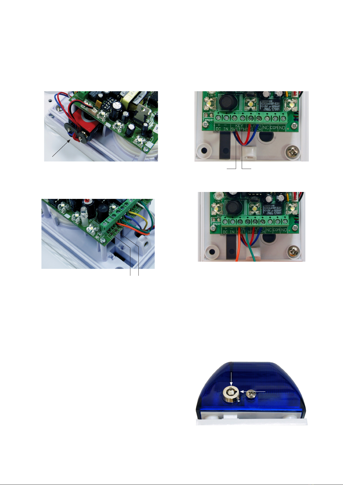
They offer alarm indications comprising of both an initial
combined 30 second sounder and flashing beacon, followed
by a continuous flashing beacon.
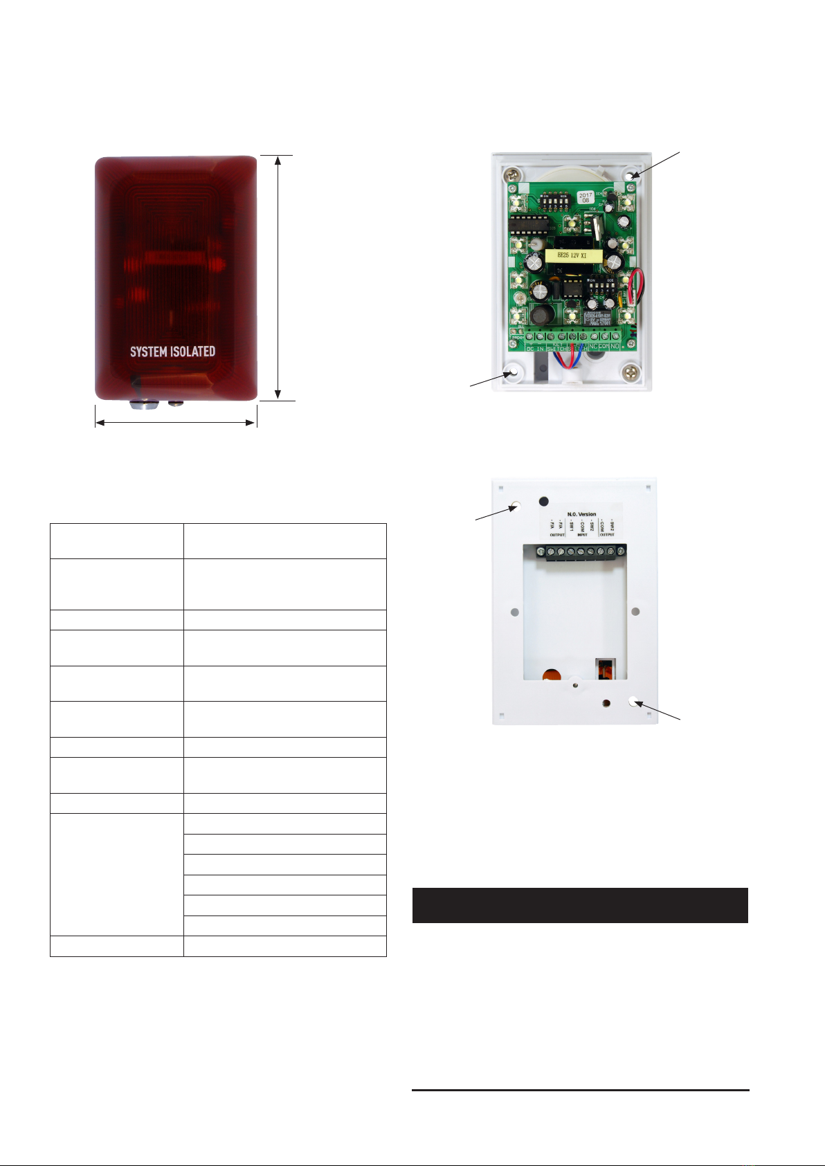
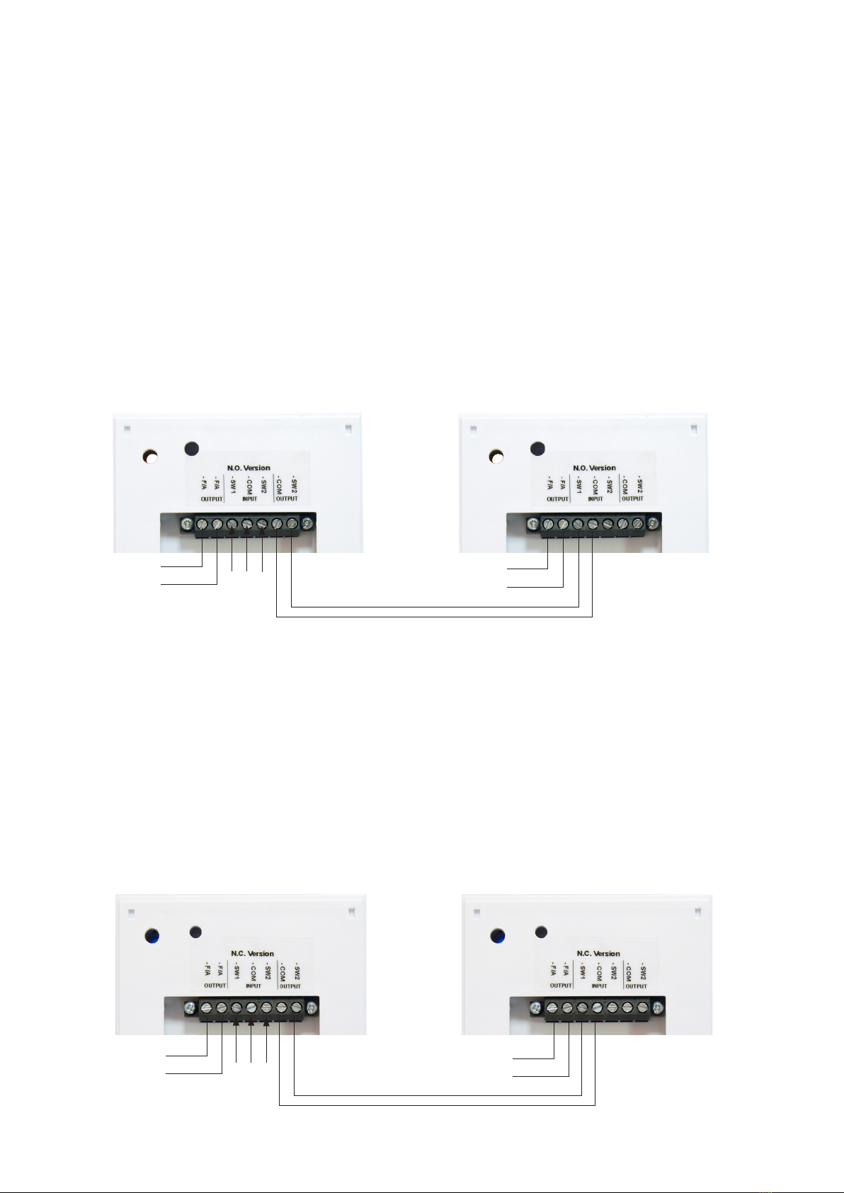
The alarm units come in three colour options for the beacon.
Each colour has two base unit options that are activated
by either Normally Open (N/O) or Normally Closed (N/C)
switches. The three colour options are orange, blue, and
red.
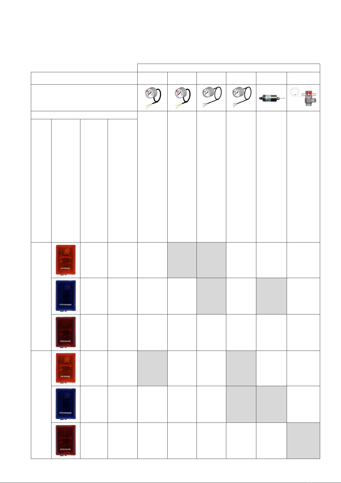
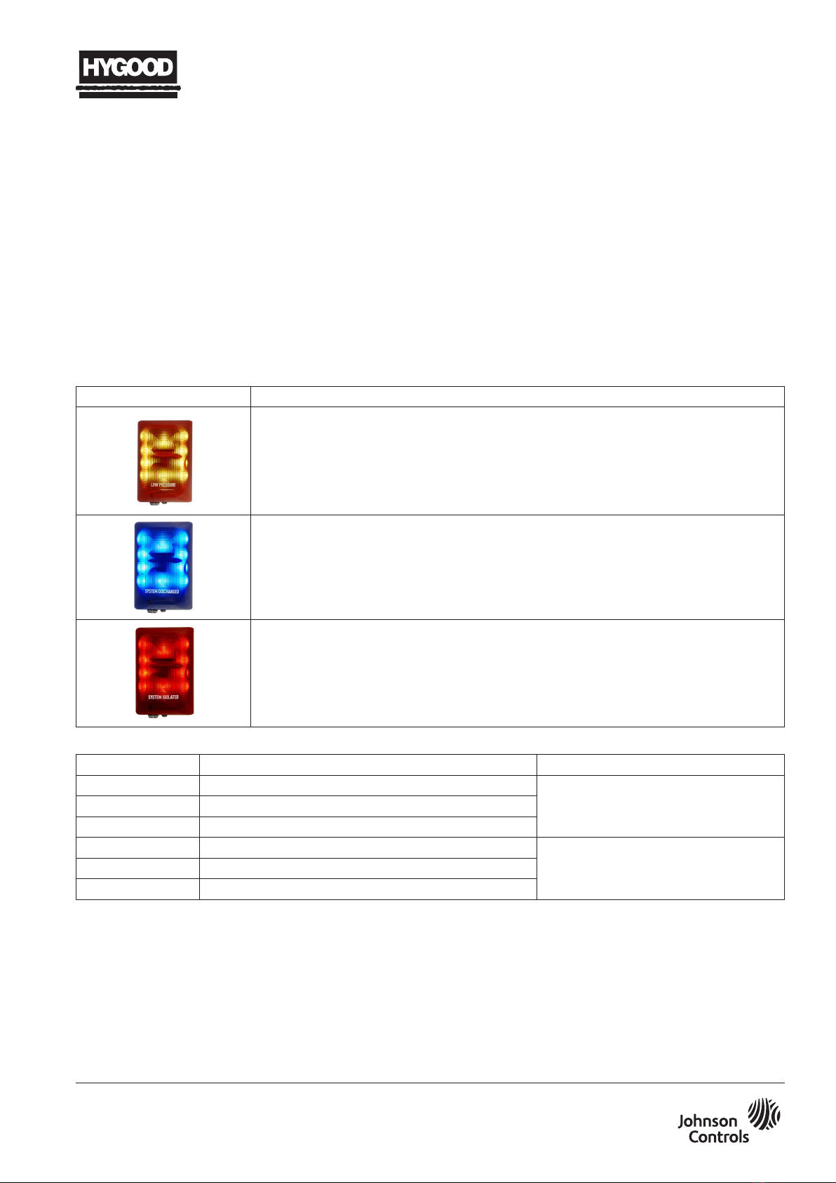
Alarm unit Description
Orange - low pressure alarm
The low pressure alarm indicates when SAPPHIRE COMPACT pressure is below the lowest
normal system operating pressure. This occurs at the lowest system operating temperature.
The low pressure alarm triggers through a pressure gauge with a switch contact. Use a
higher pressure switch contact if two fitted.
Blue - system discharged alarm
The system discharged alarm indicates when the SAPPHIRE COMPACT system discharged.
The system discharged alarm triggers through a pressure gauge with a switch contact,
pressure switch, or integrated control valve activation switch. Use a lower pressure switch
contact if two fitted.
Red - system isolated alarm
The system isolated alarm indicates when the SAPPHIRE COMPACT system valve is closed.
The system isolated alarm triggers through an integrated ball valve position switch, where
available.
Part No. Description Notes
309150001 Low pressure alarm with orange lens For use with Normally Open contacts
(N/O) when conditions are good.
(Contacts close on alarm).
309150002 System discharged alarm with blue lens
309150003 System isolated alarm with red lens
309150004 Low pressure alarm with orange lens For use with Normally Closed contacts
(N/C) when conditions are good.
(Contacts open on alarm).
309150005 System discharged alarm with blue lens
309150006 System isolated alarm with red lens

SAPPHIRE COMPACT FIXED FIRE SUPPRESSION SYSTEM
LOCAL ALARM UNITS
PAGE 2 REV. 00 2019-SEP-30
DIMENSIONS (ALL UNITS)
DEPTH = 80 mm
WIDTH = 85 mm
HEIGHT =
125 mm
FIGURE 1
E001096
TECHNICAL SPECIFICATIONS
Operating voltage: Internal power 9 VDC battery
(included)
Remote power
(optional on
installation):
12-30 VDC, 125 mA (N/O), or
200 mA (N/C)*
Operating temperature: 0 ˚C - 48.9 ˚C
Power consumption
(stand by):
50 μA (N/O); 60 μA (N/C)
Power consumption
(siren):
90 mA (N/O); 200 mA (N/C)
Power consumption
(strobe):
30 mA (N/O); 30 mA (N/C)
Siren voltage: 100 dB
Alarm indication: 30 s siren / strobe and continuous
strobe
Low battery warning: LED flash once every 60 s
Alarm switch: 309150001 - N/O contact required
309150002 - N/O contact required
309150003 - N/O contact required
309150004 - N/C contact required
309150005 - N/C contact required
309150006 - N/C contact required
Lens material: Polycarbonate
Note: *Polarity sensitive terminals
FIXING THE ALARM UNIT
FIXING HOLE -
DIA 4 mm
FIXING HOLE -
DIA 4 mm
Front
FIXING HOLE -
DIA 4 mm
FIXING HOLE -
DIA 4 mm
Reverse
FIGURE 2
E001097
1. Fix the alarm unit using the fixing hole locations in
Figure 2.
2. Use the rawl plugs and screws provided, if appropriate, or
use alternative fittings, if required.
!WARNING
All alarm units are for indoor use only. Units must be
tested periodically to verify the condition of the battery.
The 9 V battery should be changed twice a year. When the
battery is low, an indicator LED flashes every 60 seconds.
The installer must ensure that the alarm is suitable for the
purposes of alarm indication in the installation environment.
All specifications and information shown are current as of the
publication date and are subject to change without notice.

COMMISSIONING
Connecting the power supply
• Connect a 9 V battery (supplied) to the terminals and
position it as detailed in Figure 3.
FIGURE 3
E001099
• Optional: Connect the unit to remote power
(12 to 30 VDC, 125 mA (N/O) or 200 mA (N/C)).
CONNECT HERE
NOTE: POLARITY SENSITIVE
FIGURE 4
E001100
Connecting the key switch
Connect the orange and green wires from the key switch
attached to the lens.
ORANGE WIRE GREEN WIRE
Not connected
Connected
FIGURE 5
E001101
1. Using the key supplied, turn the key switch 90°, from
12 o’clock to 3 o’clock (see Figure 6), in order to set the
alarm unit.
2. To service, isolate the alarm unit by turning the key switch
90° (3 o’clock to 12 o’clock).
3. To reset the alarm unit, cycle the key switch from
3 o’clock, to 12 o’clock, and then back to 3 o’clock.
3 O’CLOCK -
ARMED
12 O’CLOCK -
ISOLATED
FIGURE 6
E001103
SAPPHIRE COMPACT FIXED FIRE SUPPRESSION SYSTEM
LOCAL ALARM UNITS
2019-SEP-30 REV. 00 PAGE 3

SAPPHIRE COMPACT FIXED FIRE SUPPRESSION SYSTEM
LOCAL ALARM UNITS
PAGE 4 REV. 00 2019-SEP-30
ELECTRICAL INSTALLATION
N/O Switches
309150001 - Normally Open contact
309150002 - Normally Open contact
309150003 - Normally Open contact
1. Always connect primary inputs to SW1 and Common on
Alarm Unit 1.
2. If using a pressure gauge with two switch contacts,
connect secondary inputs to SW2 and Common on
Alarm Unit 1.
3. If required, connect SW2 and Common outputs to SW1
and Common inputs on Alarm Unit 2.
4. For Alarm Units 1 and 2, if fitted or required, connect the
Fire Alarm (F/A) output to the Fire Alarm system.
N/C Switches
309150004 - Normally Closed contact
309150005 - Normally Closed contact
309150006 - Normally Closed contact
1. Always connect primary inputs to SW1 and Common on
Alarm Unit 1.
2. If using a pressure gauge with two switch contacts,
connect secondary inputs to SW2 and Common on
Alarm Unit 1.
3. If required, connect SW2 and Common outputs to SW1
and Common inputs on Alarm Unit 2.
4. For Alarm Units 1 and 2, if fitted or required, connect the
Fire Alarm (F/A) output to the Fire Alarm system.
FIGURE 7
E001104
FIGURE 8
E001105
N/O CONTACT
(CLOSES ON ALARM)
CONNECT TO FIRE
ALARM SYSTEM
SWITCH 1
SWITCH 2
COMMON
N/O CONTACT
(CLOSES ON ALARM)
CONNECT TO FIRE
ALARM SYSTEM
Alarm Unit 1 Alarm Unit 2
N/C CONTACT
(OPEN ON ALARM)
CONNECT TO FIRE
ALARM SYSTEM
SWITCH 1
COMMON
SWITCH 2
N/C CONTACT
(OPEN ON ALARM)
CONNECT TO FIRE
ALARM SYSTEM
Alarm Unit 1 Alarm Unit 2

SAPPHIRE COMPACT FIXED FIRE SUPPRESSION SYSTEM
LOCAL ALARM UNITS
2017-SEP-30 REV. 00 PAGE 5
SYSTEM MONITORING DEVICES
Pressure gauges with switch contacts and signal generator / pressure switches
Monitoring device Part No.
302150001 302150002
302150003 /
302150010
302150004 /
302150011 302150005
302150008 /
302150009
Monitoring device illustration
Monitoring device operation Pressure
gauge
with switch
contact, 0-40
bar, 9 bar
switch point,
M10x1.
N/C contacts
at 15 bar
nominal
charge
pressure.
Pressure
gauge
with switch
contact, 0-40
bar, 9 bar
switch point,
M10x1.
N/O contacts
at 15 bar
nominal
charge
pressure.
Pressure
gauge with
two switch
contacts,
0-40 bar, 4
bar and 9 bar
switch points,
M10x1.
N/O contacts
at 15 bar
nominal
charge
pressure.
302150010
liquid filled
variant for
environments
subject to
vibration.
Pressure
gauge with
two switch
contacts,
0-40 bar, 4
bar and 9 bar
switch points,
M10x1.
N/C contacts
at 15 bar
nominal
charge
pressure.
302150011
liquid filled
variant for
environments
subject to
vibration.
Signal
generator
/ pressure
switch
- 4.0 - 8.0 bar
switch point,
M10 x 1, 3
wire (black /
red / brown),
optional N/O
(black and
brown) or N/C
(black and
red) when
pressure
good.
302150008
DLP valve,
one outlet for
detection tube,
one outlet with
G1/8 in. plug.
with internal
ball valve and
sensor:
open - closed
(switch closed
(N/C) when
valve open),
c/w 30 bar
safety device.
302150009
DLP valve
two outlets
with internal
ball valve and
sensor:
open - closed
(Switch closed
(N/C) when
valve open),
c/w 30 bar
safety device.
Switch
mode
Alarm unit
illustration
Alarm unit
Part No.
Alarm
function
N/O
309150001
Low pressure
alarm
Operates from
N/O contact
closing
309150002
System
discharged
alarm
Operates from
N/O contact
closing
309150003
System
isolated alarm
Operates from
N/O contact
closing
N/C
309150004
Low pressure
alarm
Operates from
N/C contact
opening
309150005
System
discharged
alarm
Operates from
N/C contact
opening
309150006
System
isolated alarm
Operates from
N/C contact
opening

SAPPHIRE COMPACT FIXED FIRE SUPPRESSION SYSTEM
LOCAL ALARM UNITS
PAGE 6 REV. 00 2019-SEP-30
NOTES:
3M and Novec are trademarks of 3M Company.
HYGOOD, SAPPHIRE, and the product names in this material are marks and/or registered marks. Unauthorised use is strictly prohibited.
This manual suits for next models
5
Table of contents