HygroMatik Spa Touch Control User manual

SPA
Manual
Spa Remote Touch
READ AND SAVE THESE INSTRUCTIONS!
ÁSPART.ENoÈ
SPART.EN

SPA
Page 2
Warning, Haza rdous V oltage: All work to be pe rformed b y trained pe rsonnel on ly. All
electrical installation and servicing of the electrical components of this unit to be performed
by qualified electricians only. Disconnect power supply before installation and servicing!
Certain computer programs contained in this product [or device] were developed by HygroMatik GmbH
("the Work(s)").
Copyright © HygroMatik GmbH [17.11.2014]
SPART EN
All Rights reserved.
HygroMatik GmbH grants the legal user of this product [or device] the right to use the Work(s) solely within
the scope of the legitimate operation of the product [or device]. No other right is granted under this licence.
In particular and without prejudice to the generality of the foregoing, the Work(s) may not be used, sold,
licensed, transferred, copied or r eproduced in whole o r in p art or in a ny manner or for m other than as
expressly granted here without the prior written consent of HygroMatik GmbH.
Information in this manual is subject to change or alteration without prior notice.

SPA
Page 3
1. Introduction ....................................................................................................................... 4
1.1 Typographic Distinctions .................................................................................................................. 4
1.2 Documentation ................................................................................................................................. 4
2. Safety Notes ....................................................................................................................... 5
2.1 Overview .......................................................................................................................................... 5
2.2 Guidelines for Safe Operation .......................................................................................................... 5
2.3 Disposal after Dismantling ............................................................................................................... 6
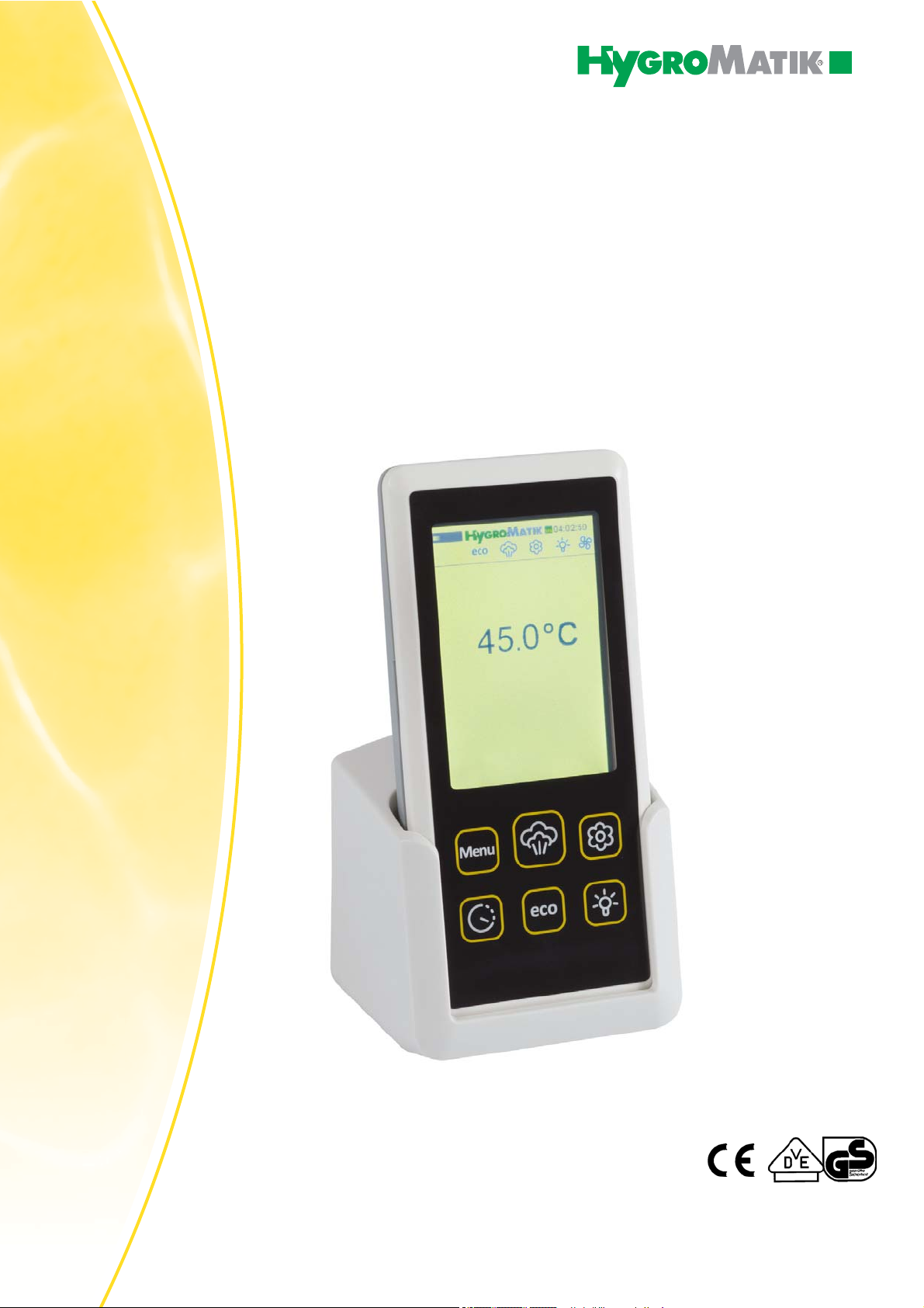
3. Brief Description Spa Remote Touch .............................................................................. 7
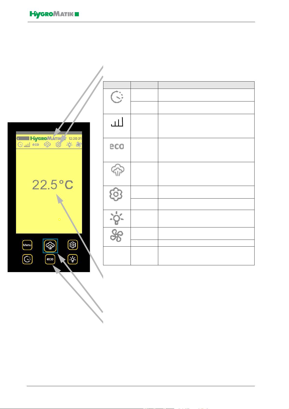
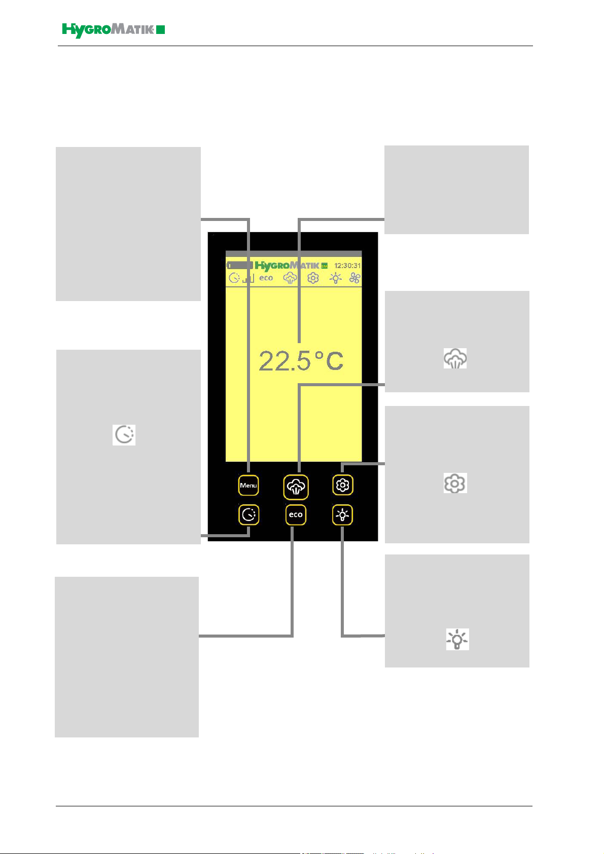
3.1 Display and Control Unit Overview .................................................................................................. 8
3.2 Operating Status LED ...................................................................................................................... 9
3.3 Quick Access Functions Overview ................................................................................................... 10
4. Operating the Spa Remote Touch on User and Operator Levels ................................. 11
4.1 Accessing the Main Menu ................................................................................................................ 11
4.2 Overview on Submenus ................................................................................................................... 11
4.3 Access to Operator Level ................................................................................................................. 12
4.4 Menu Scheme .................................................................................................................................. 13
4.4.1 Menu Steam Bath ......................................................................................................................... 14
4.4.2 Timer ............................................................................................................................................. 17
4.4.3 ECO Mode .................................................................................................................................... 19
4.4.4 Device Configuration ..................................................................................................................... 21
4.4.6 Language Selection ...................................................................................................................... 24
4.4.7 Name Plate ................................................................................................................................... 24
4.4.8 Operator Menu .............................................................................................................................. 25
5. Parameters ......................................................................................................................... 29
6. Connecting the Spa Remote Touch Charging Cradle to the Control Unit ................... 33
7. Wiring Diagram .................................................................................................................. 35

SPA
Page 4
1. Introduction
Dear Customer,
In order to operate your HygroMatik steam generator safely, properly
and efficiently, please read these operating instructions.
Employ your steam generator only in sound condition and as directed.
Consider potential hazards and safety issues and follow all the recom-
mendations in these instructions.
If you have additional questions, please contact us:
Tel.: +41 (0)31 932 01 11 (Front desk)
Tel.: +41 (0)31 932 01 11 (Technical support hotline)
Fax: +41 (0)31 931 08 67
e-mail: [email protected]
1.1 Typographic Distinctions
•preceded by a bullet: general specifications.
» preceded by an arrow: Procedures for servicing or mainte-
nance which should or must be performed in the indicated
order.
Installation step which must be checked off.
italics Terms used with graphics or drawings.
1.2 Documentation
Scope of Supply
HygroMatic steam ge nerators a re always a ccompanied by two
operating manuals, one for the unit itself and one for the control. This
manual additionally describes the operating of the Spa Remote Touch
remote control.
This doc ument is only ef fective in comb ination with the operating
instructions for th e ste am ge nerator contr ol. Wh en o perating
HygroMatik devices all safe ty regulations must be obeyed. These are
in chapter 2 of the operating manual included with the device.
Retention
Please retain these operating instructions in a secure, always accessi-
ble location. If the product is resold, turn the documentation over to the
new operator. If the documentation is lost, please contact HygroMatik.
Versions in Other Languages
These o perating instru ctions ar e available in se veral lan guages. If
interested, please contact HygroMatik (www.hygromatik.com) or y our
HygroMatik dealer.

SPA
Page 5
2. Safety Notes
2.1 Overview
These s afety no tes a re re quired by law . They pr omote wo rkplace
safety and accident prevention.
Warnings and Safety Symbols
The safety symbols below identify sections containing warnings about
hazards or potential da ngers. Please familiariz e y ourself with these
symbols.
Warning: Failure to observe this warning may result in serious injury or
death and/or damage to the unit.
Danger, Hazardous Voltage: Hazardous electrical current!
Failure to
observe this warning may result in injury or even serious injury or
death.
Warning: Failure to follow these instruc tions may result in damage to
the unit d ue to e lectrostatic discharge. Th e electronic comp onents of
the humidifier control are very sensitive to ele ctrostatic discharges. In
order to safeguard these components during installation and servicing,
steps must be taken to protect against ESD.
Reminder: M aterials an d c onsumables must be handled an d/or dis-
posed of as required by law.
Note: Appears before explanations or cross-references which refer to
other sections of the operating instructions.
2.2 Guidelines for Safe Operation
Overview
Obey all safety notes and warnings present on the unit.
In case of a malfunction, switch off the unit immediately and prevent a
restart. Repair malfunctions promptly.
After any repair work, have qualified personnel check th e safe op era-
tion of the unit.
Use original spare parts only.
Additional national safety regulations also fully apply to the operation of
this unit.
Warning: En sure tha t no skin contact to hot steam ca n occur in the
immediate area of the steam feed.
Warning: Ensur e that po ssible co ndensate fr om the lo cation o f the
steam feed cannot fall onto the skin.

SPA
Page 6
Accident Prevention Regulations
Please comply with the relevant accident prevention regulation to pre-
vent injury to yourself and others.
Operation of the Unit
Do not perform any work which compromises the safety of the unit.
Regularly check that all safety an d monitoring devices are functioning
normally.
Do not remove or disable safety devices.
Installation, Dismantling, Maintenance and Repair of the Unit
Disconnect unit comp onents from power supply prior to maintenance
or repair work.
Attaching or installing additional components is permitted only with
the written consent of the manufacturer.
When installing a humidifier in a room without a drain, a safety device
must be p rovided in th e ro om to e nsure closur e of the h umidifier’s
water supply in the event of a leak.
Electrical
Work on the electrical system must be performed by qu alified person-
nel.
Disconnect unit components from power supply prior to work.
In case of a malfunction in the electrical power supply, switch of f the
unit immediately.
Use only original fuses with the appropriate amperage rating.
Regularly ch eck the un it's electric al equipment. Pr omptly r epair a ny
damage, su ch as lo ose con nections o r b urned wi ring. Af ter p roper
electrical inst allation or rep air, test all safety mechanis ms (s uch as
grounding resistance).
HeaterSlim steam humidifiers are IP20 protected. Make sure that the
unit is protected from drips in its installed location.
2.3 Disposal after Dismantling
Note: The operator is responsible for the disposal of unit co mponents
as required by law.

SPA
Page 7
3. Brief Description Spa Remote Touch
For cha rging the S pa Remote
Touch is put in the charging cra-
dle. T he cr adle ca n be wall-
mounted by m eans of a bracket
or just be p laced o n a t able
When not in the cradle the Spa
Remote Touch can be run for up
to thr ee hours on the b atteries
inegrated in th e r emote co ntrol.
The charging cradle is per man-
antly connected to the steam generator through a communication and
supply line.
Touch screen usage
Please note: For se lection of a fu nction tap in the middle of an ico n.
Please, touch only very gently since the touch screen is very sensitive
and reacts to the faintest contact.

SPA
Page 8
3.1 Display and Control Unit Overview
The display is de signed as a ba cklit touchscreen. When switching on
the steam generator, the display shows the following:
- the HygroMatik logo (or an alternative logo) and the time of
day
- an overview bar for the current states of the functions:
- The current actual temperature in the steam bath. Improper
temperature values are indicated by arrows showing up or
down. This area also is the touch screen interface. Operating
menus and submenus for the setting of parameters are dis-
played here.
- Operating status LED
- Six quick access keys for steam bath functions.Tapping the
quick access keys provides instantaneous access to the
most frequently used functions:
Menu
Enable steam production
Essence injection
Timer function
ECO function
Light function
Symbol Status Description
perma-
nently on
preset Timer mode is activated
blinking steam generator is currently working in the
preselected Timer mode
perma-
nently on
communication between the display and
control unit and the steam generator is dis-
turbed
perma-
nently on
steam generator is in the preselected ECO
mode
perma-
nently on
steam generator is enabled for steam pro-
duction
perma-
nently on
essence injection is enabled
blinking essence pump is currently in operation
perma-
nently on
relay output for light is switched
perma-
nently on
supply fan or exhaust fan function is
enabled
blinking supply fan or exhaust fan is working
Failure
message
perma-
nently
In the fault case the steam generator is
switches off and distributes a specific fault
text message

SPA
Page 9
Touch S creen information:
Tap in the centre of an icon to select it.
Please tou ch th e tou chscreen only lig htly. It is sen sitive e nough to
react to a gentle touch.
3.2 Operating Status LED
The operating st atus LED indi cates d ifferent o perating st ates with
different colors.
These are:
LED Color Operating Status
light blue Filling
(the steam cylinder is supplied with water)
white Ready for Use
(the safety chain (clamp 1/2) is open; the device is
not enabled for steam production)
dark blue ECO
(device operates in ECO mode)
orange No Demand
(the requirement is below the switching-on point of
the steam generator)
green Humidifying
(steam is produced)
green blinking Service message
purple Blow-down
(cylinder water is blown-down)
flashing red Fault
(the device is switched off with an error message
on the display)
flashing yellow Safety Stop
Operating time equals the parameter set for
„Operating time limitation“. Operation is halted.
black No communication

SPA
Page 10
3.3 Quick Access Functions Overview
Essence function
Tapping this key switches the
essence injection enabling on
and off. If enabled the status ba
shows this icon:
A blinking icon shows that the
essence pump is currently
operated.
Release steam production
On tapping this button the unit is
enabled to produce steam and
the status bar shows:
Timer function
Tapping the key allows for
setting the timer functions.
If a timer function is activated
this icon appears in the status
bar:
A blinking icon indicates that the
unit is working in timer mode.
Hourly, daily or weekly timer
functions can be set on operator
level.
Menu function
Tapping on the key
MENU
takes you to the main menu with
the submenus:
Steam bath
Timer
ECO
Device configuration
Language
eco
ECO function
If the ECO function is activated,
the steam generator cuts normal
steam operation and this icon
appears in the status bar:
Steam generation is still
activated in regular intervals but
with reduced output.
Set temperature value
Tap on the display in the
position where the temperature
is shown. You can change the
set temperature with the
displayed up or down arrows.
Light function
Tapping the key can switch the
light function on or off.
If the light function is switched
on, the light icon appears in the
status bar:

SPA
Page 11
4. Operating the Spa Remote Touch on User
and Operator Levels
The User level allows limited access to the most important parameters
for daily use. Switching on the device generally takes you to the user
level.
The Operator le vel also provides exp anded a ccess to additional
parameters. Only password entry activates the operator level. If there
has not been an entry for a period of 15 minutes, control automatically
switches back to the user level.
Additionally, restricted use of th e Spa Remote Control is possible on
Guest Level, which only allows for the display of the steam bath nomi-
nal tem perature an d switchin g the essence do sing on an d of f. Fr om
guest lev el t he re turn to us er lev el r equires a 5 ch aracter n umeric
password that can be set on operator level.
Note: The fu nctions tha t are accessible only o n operator le vel a re
highlighted in grey in the following description.
4.1 Accessing the Main Menu
The main menu is a ccessed by touching the menu key ( the operator
menu can only be accessed on operator level, as shown further down).
4.2 Overview on Submenus
Steam bath
Timer
ECO
Device configuration
Language
Operator menu
Main menu
Steam bath
Timer
ECO
Device configuration
Main menu
Name plate
Operator menu
limited access on user level
and
expanded access on operator level
Access on operator level only
When this symb ol is
touched the menu expands
to the next page

SPA
Page 12
4.3 Access to Operator Level
Approach:
Selecting Menu / Device co nfiguration offers ac cess to the
submenus "Password level“ and "Key tones".
» Please select Password level
»Select Password entry
» Type in code 010 for settings
» Quit the menu with
Before any password input has taken place the Spa Remote Control is
on user level as shown by the „User“ indication in white in the appropri-
ate display field. After typing in „010“ as an access code the character
colour changes to grey. Instead of „Password entry“, „Operator“ is dis-
played as the status indication for the operator level.
For entry of an other access code some time later User must be to u-
ched first in order to allow for a new password entry.
Passwort Level
Code 000 -> Code 010
Password level
Key tones
Device Configuration
Authorization required!
010
Password Level
User
Password entry

SPA
Page 13
4.4 Menu Scheme

SPA
Page 14
4.4.1 Menu Steam Bath
Approach:
Selecting Menu / Steam bath offers you the following submenus:
• Essence
• Temperature
•Light
•Fan (only visible on operator level)
4.4.1.1 Essence
»Select Steam bath
»Select Essence
Essence supply is se t to „on“ when acce ssing the me nu for the first
time.
Switching off the essence supply:
»Select Off to switch off essence supply
» Quit the menu with
» For switching the essence supply on, reenter the essence
submenu and select On
Intensity
»Select Intensity to set the intensity of the essence
» The intensity grade selected is shown in a 11-stage diagram
» Touch the diagram in order to change the intensity value
» By touching the up/down arrows the intensity grade can be
changed from one bar (lowest grade) to eleven bars (highest
grade)
Factory set ting is 6 b ars co rresponding t o a n in jection tim e of 2
seconds and a pause time of 5 minutes. Setting less bars will increase
the p ause time whereas the setting of more bars will increase the
injection time.
Essence
On
Off
Intensity
Intensity
5 min Pause time
2 s Injection time

SPA
Page 15
4.4.1.2 Temperature
»Select Steam bath
»Select Temperature
Changing the temperature set value of the steam bath:
»SelectTemperature set value to change the set temperature
» Select a value between 20°C and 49°C and confirm the entry
» Quit the menu with
Adjusting the hysteresis of the temperature control:
»Select Hysteresis Temp.(this parameter defines the
temperature value for cutting the steam production with
respect to the temperature set value)
»Select a value between 0K and +10K (entry in 1K steps
possible) and confirm the entry
»Quit the menu with
Adjusting the hysteresis for stopping steam production and gene-
rating the „Error °C Max“ alarm message
»Select Hysteresis Temp. max (this parameter determines at
which temperature with respect to the temperature set value
steam generation is cut and the alarm „Error °C max“ is
generated
»Select a value between 0K und +10K (entry in 1 K steps
possible) and confirm the entry
»Quit the menu with
4.4.1.3 Light
»Select Steam bath
»Select Light
Light (on/off)
»Select On to switch on light control or
»Select Off to switch off light control
» Quit the menu with
Light on power-up of the steam generator (on/off)
»Select On for switching on light control on start-up of the
steam generator
»Select Off, for swiching off light control on start-up of the
steam generator
» Quit the menu with
Temperature
Hysteresis Temp. max
10 K
1 K
45,0 °C
Temperature set value
Hysteresis Temp.
Light
Light on power-up
Off
On
On
Off

SPA
Page 16
4.4.1.4 Fan
»Select Steam bath
»Select Fan
»Select Exhaust fan or Supply fan to set the switching function
of the according fan
»Select Follow-on time to make the fans run an additional time
after steam production was switched off
The fans can be switched off completely or run in „Permanently on“ or
„Automatic“ m ode. Wh en r un in „ Automatic“, h ysteresis ca n be
changed. Follow-on time refers to both fans, if activated.
Switching function of exhaust fan and supply fan
Switch off
»Select Off to switch off the fan function
»Quit the menu with
Switch on permanently
»Select Permanently On to set the according fan for
permanent operation
»Quit the menu with
Changing the switch-off temperature (hysteresis) of the fan
»Select Automatic
»Select Hysteresis to set the temperature hysteresis (set
temperature minus hysteresis = switch off temperature of the
fan) of the according fan
»Select a value between 0K and +10K and confirm the entry
»Quit the menu with
Setting the follow-on time
»Select Follow-on time
»Type in a time value in the range of 0 to 255 minutes
»Confirm by pressing OK or discard by using the ESC button
»Quit the menu with
Please note: The fans can o nly run in follow-on time when the main
switch of the unit is still „on“, i.e. switching-off of the steam generator
was accomplished by opening the security chain.
Supply fan
Fan
Exhaust fan
Follow-on time
Supply fan
Off
Permanantly on
Automatic
Hysteresis
1K
Exhaust fan

SPA
Page 17
4.4.2 Timer
Approach:
Selecting Menu / Timer make the following submenus available.
•On
•Off
•Modes
•Inactivity mode
•Settings
4.4.2.1 On
»Select On to switch on the timer function
» Quit the menu with
4.4.2.2 Off
»Select Off to switch off completely the timer function
»Quit the menu with
4.4.2.3 Modes
The following timer modes are available:
•Hourly
•Daily
•Weekly
Setting of the re levant times ca n be made in Settings. The pr ogram
selected is shown in the display.
Select timer mode
»Select Modes
»Select the mode intended by using the up/down arrows
»Confirm by pressing OK or discard by using the ESC button
»Quit the menu with
Timer
On
Off
Mode
Weekly program
Inactivity mode
Steam production cut-off
Settings

SPA
Page 18
4.4.2.4 Inactivity Modes
The inactivity mode selected defines the operation of the steam gene-
rator when timer control is not in the active phase.The following inacti-
vity modes are available:
•Steam production cut-off
•ECO temperature
The mode selected is shown in the display.
Selection of inactivity mode
»Select Inactivity mode
»Using the up/down arrows select Cut steam production or
ECO temperature
»Confirm by pressing OK or discard by using the ESC button
»Quit the menu with
4.4.2.5 Settings
Settings for hourly program
This setting allows for the definiti on of th e stea m p roduction pe riod.
After timer start the remaining period is displayed in the button field.
Steam production period
»Select Steam production period after preselecting Hourly
program
»Type in a value in the range from 20 to 999 minutes
»Confirm by pressing OK or discard by using the ESC button
»Quit the menu with
Settings for daily program
The daily program allows for two steam production intervals to be pre-
set for every individual day of the week (Monday to Sunday).
Selection of day of the week
»Select the day of the week in question after preselection of
Daily program
»Quit the menu with
Hourly program
Time left
1 min
Steam production period
30 min
Daily program
Monday
Tuesday
Wednesday
Thursday

SPA
Page 19
Setting intervals (see also „Setting the weekly program“)
»Select after preselection of the day of the week Interval 1 on
or Intervall 1 off (and Interval 2 on/off resp.)
»Type in the times for start and stop of steam production
»Confirm by pressing OK or discard by using the ESC button
»Quit the menu with
Settings for the weekly program
The weekly program allows the preselection of two intervals for steam
production that are running on each day of the week (Monday to Sun-
day) in the same way .
Setting intervals
»Select Interval 1 on or Interval 1 off (and Interval 2 on/off
resp.) after preselection of „Weekly program“
»Type in the times for start and stop of steam production
»Confirm by pressing OK or discard by using the ESC button
»Quit the menu with
4.4.3 ECO Mode
The steam generator stops actual steam operation if the ECO function
is activa ted. The eco ico n app ears in the status ba r. The steam
cylinder is ac tuated regularly bu t th e st eam generator is wo rking on
reduced output.
Approach:
By selecting Menu / ECO mode the following submenus are available:
•On
•Off
•Settings
4.4.3.1 Switch on ECO mode
»Select On
» Quit the menu with
»
4.4.3.2 Switch off ECO Mode
»Select Off
» Quit the menu with
Intervall 2 Aus
Intervall 2 Ein
Intervall 1 Aus
00:00
00:00
00:00
Weekly program
Interval 1 on
00:00
Interval 1 off
00:00
Interval 2 on
00:00
Interval 2 off
00:00
ECO
On
Off
Settings

SPA
Page 20
4.4.3.3 ECO Settings
The ECO settings allow for choosing among the functions
•Stand-by heating or
•Temperature preservation
During S tand-by heating, actua l steam bath ope ration (stea m
production) is inter rupted. However, the cylinder wa ter is heated
periodically fo r a set he ating-on period fo llowed by th e he ating-off
period. After that, the heating will be on again, and so on.
During Temperature preservation, actual steam bath operation (steam
production) is in terrupted. However, th e steam bath is n ow kept a t a
set-point temperature lower than the standard value.
Please note: Standby-Heating and temperature preservation can not
be active at the same time.
Selection of the ECO function intended
»Select ECO Settings
»Select one of the functions Stand-by heating or Temperature
preservation
»Quit the menu with
Setting the stand-by heating parameters
»Select Interval time (entry of the time in minutes) or Heating
time (entry of the time in seconds)
»Set the intended duration values and confirm the entries
»Quit the menu with
Please note: It is recommended to vary the heating time in small steps
only while checking the effect after each change.
ECO Settings
Stand-by heating
Temperature preservation
Stand-by heating
Interval time
5 min
Heating time
5 s
Other manuals for Spa Touch Control
1
Table of contents
Other HygroMatik Remote Control manuals