HYPERAKTIVE Hyperkontrol User manual

Hyperkontrol
Boost Management System
Installation and Operation Manual
Page 1 of 29

HYPERKONTROL BOOST MANAGEMENT SYSTEM: INSTALLATION AND OPERATION MANUAL
Table of Contents
INTRODUCTION.....................................................................................................................................3
DISCLAIMER...........................................................................................................................................4
PRODUCT PACKAGE CONTENTS........................................................................................................5
OPERATIONAL MODES.........................................................................................................................6
MPH Mode............................................................................................................................................6
Time Mode............................................................................................................................................6
MPH Wheel R ce..................................................................................................................................6
MPH Wheel Street.................................................................................................................................6
Dyno......................................................................................................................................................6
ADDITIONAL FEATURES......................................................................................................................7
Zoom nd Reduce Switches..................................................................................................................7
Pre-L unch............................................................................................................................................7
D t Logging nd Comp rison..............................................................................................................7
M x Boost.............................................................................................................................................7
PRODUCT INSTALLATION....................................................................................................................8
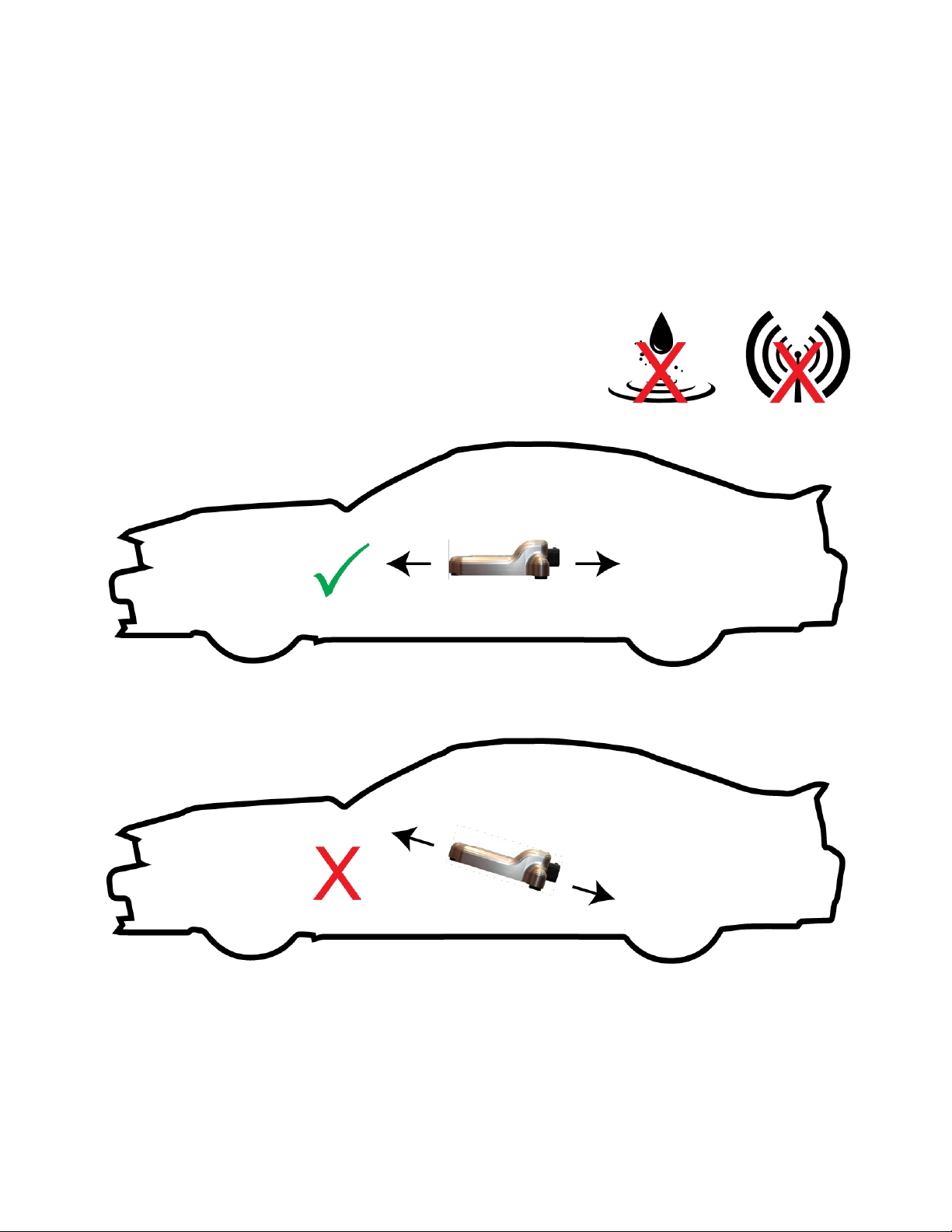
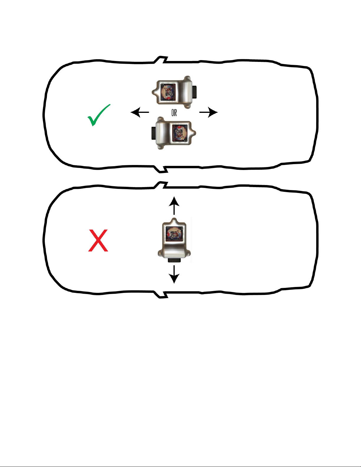
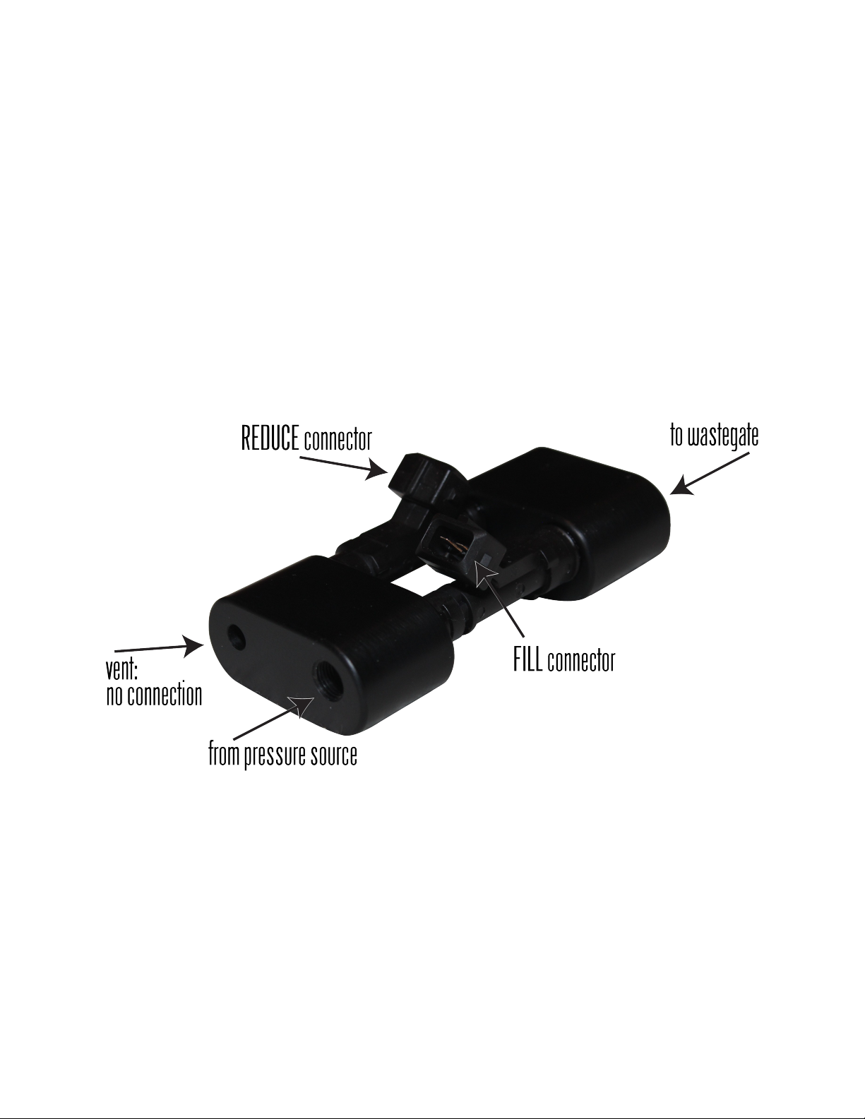
Mounting nd Plumbing........................................................................................................................8
Wiring nd Lights................................................................................................................................12
HYPERKONTROL SOFTWARE............................................................................................................16
GENERAL OPERATION OF HYPERKONTROL & SOFTWARE.......................................................18
Boost M n gement Theory with Hyperkontrol...................................................................................18
Hyperkontrol Softw re Menu..............................................................................................................18
Initi l Set-Up of Hyperkontrol............................................................................................................18
PROGRAMMING AND USING THE HYPERKONTROL...................................................................22
Entering V lues....................................................................................................................................22
Zoom, Reduce nd Pre-L unch...........................................................................................................23
Gr ph Are ..........................................................................................................................................23
Dyno Mode..........................................................................................................................................23
Sending / Receiving D t ....................................................................................................................23
Working With Files..............................................................................................................................24
DRIVING THE VEHICLE - DRAG STRIP............................................................................................25
The Burnout.........................................................................................................................................25
St ging.................................................................................................................................................25
St ged..................................................................................................................................................26
L unch.................................................................................................................................................26
After the Run.......................................................................................................................................26
DRIVING THE VEHICLE - “STANDING MILE”................................................................................26
DRIVING THE VEHICLE - “STREET RACE”.....................................................................................26
TROUBLESHOOTING...........................................................................................................................27
APPENDIX A – NHRA PRO MOD INSTALLATION...........................................................................28
Boost Sensor........................................................................................................................................28
APPENDIX B – MOUNTING DIAGRAM............................................................................................29
Page 2 of 29

HYPERKONTROL BOOST MANAGEMENT SYSTEM: INSTALLATION AND OPERATION MANUAL
INTRODUCTION
Th nk you for purch sing the Hyperkontrol Boost M n gement System. We truly believe it represents
the next level in competition-gr de boost control. We sincerely ppreci te th t you h ve chosen
Hyper ktive Perform nce Solutions to help you with your boost control, nd we hope th t this product
will exceed your highest expect tions.
This instruction m nu l will expl in some of the concepts of the oper tion of the Hyperkontrol Boost
M n gement System, nd will show you how to properly inst ll, configure, nd use it. If this is your
first time using Hyper ktive Perform nce Solutions product, or if you’re veter n, we hope th t this
instruction m nu l will provide you with the inform tion you need to m ximize your use of the
Hyperkontrol Boost M n gement System.
Should you h ve ny questions or require technic l ssist nce, feel free to c ll (847) 321-1982, em il
s les@hyper ktiveps.com , or post your question in the “Electric l” section on the YellowBullet.com
forums which we proudly sponsor.
Sincerely,
Joe Opl wski
Hyper ktive Perform nce Solutions
joe@hyper ktiveps.com
www.hyper ktiveps.com
Page 3 of 29

HYPERKONTROL BOOST MANAGEMENT SYSTEM: INSTALLATION AND OPERATION MANUAL
DISC AIMER
It is the responsibility of the purch ser to follow ll guidelines nd s fety procedures supplied with this
product. Any other m nuf cturer's products used with this product must h ve their guidelines nd
s fety procedures ppropri tely followed. It is lso the responsibility of the purch ser to determine
comp tibility of this device with the vehicle nd other components used in the oper tion of this
product.
Hyper ktive Perform nce Solutions ssumes no responsibility or li bility for d m ges resulting from
ccident, improper inst ll tion, misuse, buse, improper oper tion, l ck of re son ble c re,
incomp tibility with other products or components, or ny other re sons.
Hyper ktive Perform nce Solutions ssumes no responsibility or li bility for d m ges resulting during
the use of products m nuf ctured or sold by Hyper ktive Perform nce Solutions on vehicles used for
r cing or competition purposes.
Hyper ktive Perform nce Solutions neither recommends nor pproves the use of products
m nuf ctured or sold by Hyper ktive Perform nce Solutions on vehicles which m y be driven on
public highw ys or ro ds, nd ssumes no responsibility or li bility for d m ges resulting from such
use.
Inst ll tion, correctly or otherwise, of this product signifies th t you h ve re d this document nd gree
to the terms nd conditions for use st ted within.
Page 4 of 29

HYPERKONTROL BOOST MANAGEMENT SYSTEM: INSTALLATION AND OPERATION MANUAL
PRODUCT PACKAGE CONTENTS
Your p ck ge should include the following items:
Hyperkontrol m in unit
Hyperkontrol solenoid v lve ssembly
Two pressure sensors (0-75 PSI or 0-75 PSI boost nd option l 0-100 PSI w steg te)
Seri l communic tions c ble
Wiring h rness
Ple se inspect your p ck ge contents for completeness before beginning inst ll tion. If you should find
th t component h s not been included, ple se cont ct Hyper ktive Perform nce Solutions s soon s
possible by c lling (847) 321-1982 or em iling s les@hyper ktiveps.com.
Page 5 of 29

HYPERKONTROL BOOST MANAGEMENT SYSTEM: INSTALLATION AND OPERATION MANUAL
OPERATIONA MODES
The Hyperkontrol Boost M n gement System is one of the most dv nced boost control products
v il ble on the m rket tod y. Gener lly spe king, the Hyperkontrol unit controls boost pressure by
m nipul ting g s pressure t the w steg te. This is chieved by c refully controlling the solenoid v lve
ssembly. As the user, you simply configure the softw re for the desired pressures t the w steg te nd
the Hyperkontrol t kes c re of the rest. Addition lly, Hyperkontrol llows you to configure two ground-
switched uxili ry outputs.
Hyperkontrol offers four modes of oper tion th t support lmost ny r cing scen rio:
MPH Mode
In MPH Mode, Hyperkontrol uses n intern l ccelerometer nd other components to determine the
vehicle's speed from initi l l unch to 250 MPH. Users will configure Hyperkontrol to m nipul te
w steg te pressure b sed on the vehicle's speed in 1 MPH increments (for ex mple, 55 PSI of
w steg te pressure t 163 MPH).
Time Mode
In Time Mode, Hyperkontrol llows the user to specify w steg te pressure b sed on el psed time since
the l unch, in 0.05 second increments up to 12.5 seconds (for ex mple, 55 PSI of w steg te pressure t
3.65 seconds).
MPH Wheel Race
MPH Wheel R ce mode is used for street c rs, “Tex s Mile”, Bonneville/l nd speed nd etc. Use of
this mode requires vehicle speed sensor. Simil r to MPH nd Time modes, MPH Wheel R ce mode
uses l unch input to signify the beginning of the run nd begin d t logging.
MPH Wheel Street
MPH Wheel Street mode is simil r to MPH Wheel R ce mode. It requires vehicle speed sensor but it
does not use l unch input nd does not d t log.
Dyno
Technic lly, dyno mode is not “competition” mode. However, it is n dv nced mode th t llows
users to view ll of the sensors nd switches the Hyperkontrol knows bout in re l-time. Dyno mode
llows the user to specify desired w steg te pressure nd the Hyperkontrol will m int in this
pressure. This mode provides n excellent tuning tool to id in determining the rel tionship between
w steg te pressure nd m nifold/boost pressure on specific vehicle. Dyno mode c n lso ct s
di gnostics nd troubleshooting tool for both the Hyperkontrol system, finding system le ks nd more.
Page 6 of 29

HYPERKONTROL BOOST MANAGEMENT SYSTEM: INSTALLATION AND OPERATION MANUAL
ADDITIONA FEATURES
Hyperkontrol provides sever l unique ddition l fe tures th t sets it p rt from other boost controllers:
Zoom and Reduce Switches
Hyperkontrol h s two switch inputs for “Zoom” nd “Reduce”. While the Zoom switch is ctiv ted,
Hyperkontrol will dd the configured pressure t the w steg te in ddition to the current setting. For
ex mple, if Zoom is configured for 10 PSI nd t 63 MPH the Hyperkontrol is set to 30 PSI, ctiv ting
the Zoom switch t 63 MPH will c use Hyperkontrol to m int in 30 (b se) + 10 (Zoom) or 40 PSI tot l
t the w steg te.
In Zoom mode, Hyperkontrol will only dd w steg te pressure until the configured m x boost level is
re ched. In the ex mple bove, if m x boost is hit t 33 PSI of w steg te pressure, Hyperkontrol will
not ttempt to re ch the full 40 PSI (30 + 10). Simil rly, the Reduce switch will c use reduction in
w steg te pressure below the current setting. Using the ex mple bove, ctiv ting the Reduce switch t
63 MPH will c use Hyperkontrol to m int in 30 (b se) - 10 (Reduce) or 20 PSI tot l t the w steg te.
These switches c n be ctiv ted by the driver. If they re controlled by the engine m n gement system,
dv nced boost control nd/or tr ction control scen rios c n be devised.
Pre- aunch
The pre-l unch setting is nother unique fe ture of the Hyperkontrol. The setting for pre-l unch
represents the pressure th t will be m int ined t the w steg te fter “R ce” is en bled but before
“L unch”. Pre-l unch gives the user more fine-gr ined control of boost pressure fter the burnout but
before the run h s st rted. This setting is typic lly used with c rs th t footbr ke in order to ssist in
spooling during st ging.
Data ogging and Comparison
Hyperkontrol will log d t throughout the run, nd connecting the softw re to the controller will llow
users to view the ctu l w steg te nd boost pressures. Addition lly, these v lues c n be s ved or
lo ded comp rison purposes. The Hyperkontrol softw re will llow users to comp re the current
settings, the ctu l v lues from the run, nd previous settings in both t ble nd gr phic l form t.
Max Boost
Unlike m ny boost controllers, Hyperkontrol lso en bles the user to configure m ximum boost
pressure t ll d t points. This ensures th t, reg rdless of the w steg te setting, no more boost will be
m de. This c n be v lu ble tuning tool for exploring new w steg te pressures, new plumbing, or even
new w steg tes. Addition lly, the M x Boost setting c n ct s s fety in c se of f ilure of the
w steg te pressure sensor. If the w steg te pressure sensor h s f iled before the run st rts, the
Hyperkontrol system will not ctiv te. But, if the w steg te sensor f ils fter l unch, Hyperkontrol will
ttempt to control the boost by m nipul ting the w steg te pressure utom tic lly.
Page 7 of 29

HYPERKONTROL BOOST MANAGEMENT SYSTEM: INSTALLATION AND OPERATION MANUAL
PRODUCT INSTA ATION
Mounting and Plumbing
The Hyperkontrol Boost M n gement System h s precisely c libr ted ccelerometer inside. Bec use
of this, it is extremely import nt to mount the unit properly.
The Hyperkontrol unit
1. must be mounted inside the vehicle on the included rubber vibr tion isol tion mounts.
2. must be mounted in loc tion where it will not be exposed
to moisture or electrom gnetic interference (EMI). For
ex mple: do not mount it next to ignition modules
3. must be mounted perfectly level, with the l bel f cing up
Page 8 of 29

HYPERKONTROL BOOST MANAGEMENT SYSTEM: INSTALLATION AND OPERATION MANUAL
4. must be mounted with the connector in-line with the direction of tr vel (f cing front or re r)
F ilure to mount the unit properly m y result in imprecise boost control ( t best) or unintended
oper tion ( t worst). When in doubt, cont ct Hyper ktive Perform nce for guid nce on proper
mounting nd inst ll tion.
As progr mming the unit requires connecting the seri l c ble, it is suggested to mount the unit in n
ccessible loc tion, or to m ke seri l c ble to the ppropri te length to re ch the unit t ll times.
Page 9 of 29

HYPERKONTROL BOOST MANAGEMENT SYSTEM: INSTALLATION AND OPERATION MANUAL
The Solenoid Valve Assembly
1. must be pl ced close to the w steg tes
2. must use the mounting holes provided
The solenoid v lve ssembly h s two electric l connections - one for e ch solenoid. M ke sure to
connect the ppropri tely l beled connector to the solenoid indic ted in the picture bove.
FILL: The fill side is connected to the pressure source (for ex mple, the CO2 bottle). It h s 1/8 NPT
fitting nd sm ller port. The sm ller port is to llow the REDUCE solenoid to vent excess pressure.
DO NOT ttempt to connect nything to the empty port on the solenoid v lve ssembly. Blocking or
connecting nything to the vent m y result in imprecise boost control or m y d m ge the solenoid
v lve ssembly.
REDUCE: The reduce side is connected to the w steg te pressure control input.
F ilure to properly mount the solenoid v lve ssembly m y result in imprecise boost control. The
further the solenoid v lves re from the w steg te, the slower the response time.
The Pressure Sensors
1. must be mounted directly on or fed directly from the int ke m nifold (boost pressure sensor)
2. must be mounted directly on the w steg te (w steg te pressure sensor)
3. must not be mounted directly on the solenoid v lve ssembly (w steg te pressure sensor)
F ilure to mount the boost pressure sensor either directly on or using short tube connecting to the
int ke m nifold will result in imprecise boost pressure re dings nd m y ffect the perform nce of the
M x Boost settings.
Page 10 of 29

HYPERKONTROL BOOST MANAGEMENT SYSTEM: INSTALLATION AND OPERATION MANUAL
Mounting the w steg te pressure sensor on the output of the solenoid v lve ssembly will result in
unintended oper tion of the controller. The solenoid ssembly's oper tion will c use err tic w steg te
pressure re dings, which will le d to unintended oper tion of the controller. Mounting the w steg te
pressure sensor on the w steg te is good choice.
Wastegate Plumbing
The following di gr m illustr tes proper plumbing for vehicle with single w steg te. Note th t
st inless steel T should be used to tt ch the pressure sensor if the w steg te only h s one port.
For vehicles with two (or more) w steg tes, inst ll the sensor on one w steg te nd use T connections
to the other w steg tes.
Page 11 of 29

HYPERKONTROL BOOST MANAGEMENT SYSTEM: INSTALLATION AND OPERATION MANUAL
Wiring and ights
The Hyperkontrol Boost M n gement System comes with pre-wired h rness th t h s both termin ted
nd non-termin ted connections. The connections re det iled in the following t ble nd pictures.
Connector or Color Function
Bl ck Ground
Red Power (+12V)
Purple R ce Mode
Blue L unch
Green Zoom
Brown Reduced
Yellow AUX Output 1
White AUX Output 2
GATE G te Pressure Sensor
BOOST Boost Pressure Sensor
FILL Fill Solenoid
REDUCE Reduce Solenoid
3-pin Deutcsh Progr m selector
4-pin Deutsch VSS (Vehicle Speed Sensor)
DB9he Seri l Communic tions
23-pin AMP The m in connector to plug into the controller
Lights
There re two lights on the Hyperkontrol unit. One to indic te the unit h s power, the other to indic te
R ce Mode is ctive.
Power and Ground
M ke sure the power nd ground connections re isol ted from electric l noise. For ground, direct
connection to the b ttery or b ttery c ble run to the center of the c r is preferred. For power, +12V
sign l switched with the m in power is recommended.
Ra e and Laun h
The r ce nd l unch connections m y either be switched +12V or switched ground. You c n configure
the softw re depending on whether you will switch +12V or ground to e ch connection.
Zoom and Redu e
The Zoom nd Reduce functions re ctiv ted by connecting them to ground ONLY.
Page 12 of 29

HYPERKONTROL BOOST MANAGEMENT SYSTEM: INSTALLATION AND OPERATION MANUAL
Solenoid Valve Assembly
The connectors should be ppropri tely tt ched to the solenoid v lve ssembly.
Pressure Sensors
The connection for e ch pressure sensor is l beled ccordingly.
Page 13 of 29

HYPERKONTROL BOOST MANAGEMENT SYSTEM: INSTALLATION AND OPERATION MANUAL
Program Sele tor
The Hyperkontrol Boost M n gement System llows 3-position selector switch to be tt ched to this
plug. The switch llows the user to choose from three different boost m n gement progr ms.
Hyper ktive Perform nce Solutions provides 3-position switch nd h rness for use with this
connector.
Vehi le Speed Sensor
If you wish to utilize vehicle speed sensor, you will need to properly inst ll it nd then wire nd
connect it to the 4-pin Deutsch connector. You will need DTM04-4P to m te with the Hyper ktive
h rness' connector. Hyper ktive Perform nce Solutions c n provide vehicle speed sensor nd h rness
or you c n source your own.
Note: The Hyperkontrol system will only inter ct with wheel sensor th t gener tes between 4-10
pulses per revolution.
The wiring connections for the vehicle speed sensor re:
Connector Pin
(Hypera tive Harness Color)
Function
1
(Bl ck) Ground
2
(Red/White) +5V (Supply)
3
(Brown) Sign l
4
(Red) +12V (Supply)
Page 14 of 29

HYPERKONTROL BOOST MANAGEMENT SYSTEM: INSTALLATION AND OPERATION MANUAL
Serial Conne tor
The supplied seri l communic tions c ble connects between the DB9 (seri l) connector on the
Hyperkontrol h rness nd your computer.
Main Conne tor
The 23-pin AMP connector is the m in connector th t plugs into the Hyperkontrol unit.
Auxiliary Outputs
The switched uxili ry outputs re used for connecting the Hyperkontrol Boost M n gement System to
other devices. The uxili ry inputs c n only be switched from “no connection” to GROUND. If your
connected device c nnot ccept GROUND input you will need n intermedi ry circuit or rel y to
ccommod te switching your device.
Page 15 of 29

HYPERKONTROL BOOST MANAGEMENT SYSTEM: INSTALLATION AND OPERATION MANUAL
HYPERKONTRO SOFTWARE
The computer softw re for the Hyperkontrol Boost M n gement System c n be found on our website.
1. Visit http://www.hyper ktiveps.com/boost-m n gement/hyperkontrol-boost-m n gement-
system
2. Click “Click here to downlo d our L test Softw re!!”.
3. S ve the ZIP file to your computer.
4. Right-click the st rt button nd select “Open Windows Explorer”.
5. Find the folder where you s ved the ZIP file.
6. Right-click the ZIP file nd select “Extr ct ll...”.
7. Type “C:\” in the text box.
8. Check the checkbox th t s ys “Show extr cted files when complete”.
9. Click “Extr ct”.
Page 16 of 29

HYPERKONTROL BOOST MANAGEMENT SYSTEM: INSTALLATION AND OPERATION MANUAL
10. Double-click on the Hyperkontrol folder th t you see in the new window.
11. Right-click on one of the HyperKontrol EXE files.
12. Select “Send to” nd then select “Desktop (cre te shortcut)”.
NOTE: The execut ble file with “Q” in its n me is the “quick” version of the Hyperkontrol softw re. It
h s lower resolution of time/MPH for e sier nd f ster set-up, or for users who do not require s
much precision. The Q softw re h s resolution of 0.2 seconds nd 4 MPH.
You now h ve shortcut on your desktop th t you c n double-click to run the Hyperkontrol
m n gement softw re. The first time you run the softw re you m y see w rning:
Be sure to uncheck the box th t s ys “Alw ys sk before opening this file”, or you will lw ys see this
w rning when opening the softw re.
Page 17 of 29

HYPERKONTROL BOOST MANAGEMENT SYSTEM: INSTALLATION AND OPERATION MANUAL
GENERA OPERATION OF HYPERKONTRO & SOFTWARE
Using your Hyperkontrol Boost M n gement System is not very difficult, but you should t ke
moment to f mili rize yourself with the gener l oper tion of the softw re nd, ultim tely, the
controller.
Boost Management Theory with Hyperkontrol
Gener lly spe king, the w steg te llows exh ust g s to esc pe, or w ste. Exh ust g s th t p sses
through the w steg te does not p ss through the turbine. The less g s th t p sses through the turbine,
the slower it spins, which me ns the compressor side spins slower, nd less boost is gener ted.
By pplying more pressure to the w steg te input, Hyperkontrol c n prevent the w steg te from
opening. This me ns more g s p sses through the turbine nd spins it f ster, which spins the
compressor f ster, which gener tes more boost.
Essenti lly, ll of the boost m n gement th t is done with the Hyperkontrol is chieved by ch nging the
setting of “W G te psi”. Entering v lue of “30”, for ex mple, will c use the Hyperkontrol to m int in
30 PSI of pressure on the w steg te. Whether you re in n MPH-b sed mode or Time-b sed mode,
when the desired MPH or el psed time is re ched, Hyperkontrol will pply the pressure v lue of “W
G te psi” t the w steg te.
Depending on your p rticul r combin tion of turbo, engine, w steg te nd other f ctors, different
pressures pplied t the w steg te will result in different boost pressures. You will need to tune nd
experiment to determine the w steg te vs boost rel tionship for your p rticul r set-up.
Hyperkontrol Software Menu
The Hyperkontrol softw re menu is f irly simple. All of the menus will be expl ined in this instruction
m nu l. When you run the softw re for the first time, it is import nt to perform n initi l set-up of your
Hyperkontrol's settings.
Initial Set-Up of Hyperkontrol
The first time you use the softw re, it is set to the f ctory def ult settings. You set-up the Hyperkontrol
by clicking “Setup” in the menu of the Hyperkontrol softw re. There re sever l import nt settings th t
must be configured in order for Hyperkontrol to function properly b sed on your inst ll tion. Before
you do nything else, m ke sure th t you set up your controller. Connect the seri l c ble, run the
softw re nd click “Setup” in the menu b r.
Page 18 of 29

HYPERKONTROL BOOST MANAGEMENT SYSTEM: INSTALLATION AND OPERATION MANUAL
Set Zero
With the engine off nd the c r level, click the “Set zero” button. This will zero-out nd c libr te the
v rious sensors th t the Hyperkontrol system uses. Setting the zero in this st te is very import nt, s
ny offset from zero will ffect the oper tion nd perform nce of the controller. This me ns you must
m ke sure the c r is sitting s it will go down the tr ck when setting zero. The tires should be properly
infl ted, the c r should be sitting on the tires nd not on st nds or r mps, the c r should not be in or on
tr iler, etc. The process t kes pproxim tely 6-7 seconds.
Note: If the Race Mode switch is ON, the softw re will not communic te with the unit.
Ra e and Laun h Swit h Setting
These two settings tell Hyperkontrol whether to look for +12V sign l or Ground sign l.
Controller Mount Setting
If the wiring h rness connector on the Hyperkontrol unit is f cing the front of the c r, select “tow rds
front”. If the connector is f cing the re r, select “tow rds re r”. This llows Hyperkontrol to know
when the c r is moving forw rds.
Wheel MPH Ring Teeth
The wheel MPH ring teeth setting is used to determine how m ny pulses per revolution (PPR) there re
for the sensed wheel. Hyperkontrol c n utilize sensor setup th t uses nywhere from 4-10 pulses per
revolution (PPR). Entering this v lue incorrectly will result in speed re ding th t is wrong.
Wheel MPH Tire Rollout
The tire rollout nd ring teeth settings re used together to determine the speed of the vehicle. To
me sure rollout, you c n either:
•Me sure the circumference of your tire using t pe me sure (more ccur te)
Page 19 of 29

HYPERKONTROL BOOST MANAGEMENT SYSTEM: INSTALLATION AND OPERATION MANUAL
•Multiply your tire di meter by 3.14 ( pproxim te)
For ex mple, if you me sure 78.5” circumference with t pe me sure, you would enter 78.5 for the
“Wheel MPH tire rollout” setting.
If you c lcul te with 25” tire, 25 x 3.14 = 78.5, so you would lso enter 78.5 for the “Wheel MPH tire
rollout” setting.
Aux1 and Aux2 Mode Setting
W steg te pressure, m x boost nd uxili ry output settings re configured for e ch increment (MPH or
el psed time). For ex mple, 55 PSI of w steg te pressure t 163 MPH or 3.05 sec. In the c se of the
uxili ry outputs, you would either configure “ON” (1) or “OFF” (0). For ex mple, “ON” t 163 MPH
or 3.05 sec.
There re two modes to control the oper tion of the uxili ry outputs:
•Shifter: When using MPH for Hyperkontrol, n uxili ry output configured for “Shifter” will
only ctiv te once. If the vehicle MPH f lls below the threshold, the uxili ry output will not
re ctiv te.
•Normal: In norm l mode, Hyperkontrol will en ble/dis ble the output t e ch increment (MPH
or el psed time). When Hyperkontrol is using MPH, “Norm l mode” will c use the output to
turn on nd off every time the MPH increment is crossed.
Page 20 of 29
Table of contents
Popular Automobile Accessories manuals by other brands

CEStronics
CEStronics CES OMEGA FLEX operating instructions

Gaoyi Tech
Gaoyi Tech B-228 installation guide

Rola
Rola NV2 59508 installation instructions

Cruz
Cruz Alu-Rack L13-120 Assembly instructions

KUSSMAUL
KUSSMAUL 091-18-098 installation instructions

Metra Electronics
Metra Electronics 95-6545B installation instructions