Hypersen HPS-FT Series User manual

Hypersen Technologies Co., Ltd. HPS-FT-USER V1.8
1/38
HPS-FT-USER
6-Axis Force Torque Sensor User Manual
Version: HPS-FT-USER 1.8
Host software version: Host 1.11.1.A
The manual is issued in February 2022

Hypersen Technologies Co., Ltd. HPS-FT-USER V1.8
2/38
Please read this manual carefully before use.
This user manual will be checked and revised regularly, and the updated contents will be included
in the latest version. The contents or information included in this manual will be changed without
notice.
Hypersen Technologies Co., Ltd. is not liable for any errors that may appear in this manual.
Hypersen Technologies Co., Ltd. shall not be liable for any accidental or consequential injury
arising from the use of this manual and the product described in it.
Please read this manual before installing and using the product.
Please keep this manual so that it can be read and referenced at any time.
The figures in this manual are for reference only. The actual product shall prevail.
© 2022 Hypersen Technologies Co., Ltd. – All rights reserved

Hypersen Technologies Co., Ltd. HPS-FT-USER V1.8
3/38
Table of Contents
1 Product introduction ........................................................................................................................................5
1.1 Sensor introduction ..................................................................................................................................5
1.1.1 Introduction ........................................................................................................................................5
1.1.2 Product features ................................................................................................................................5
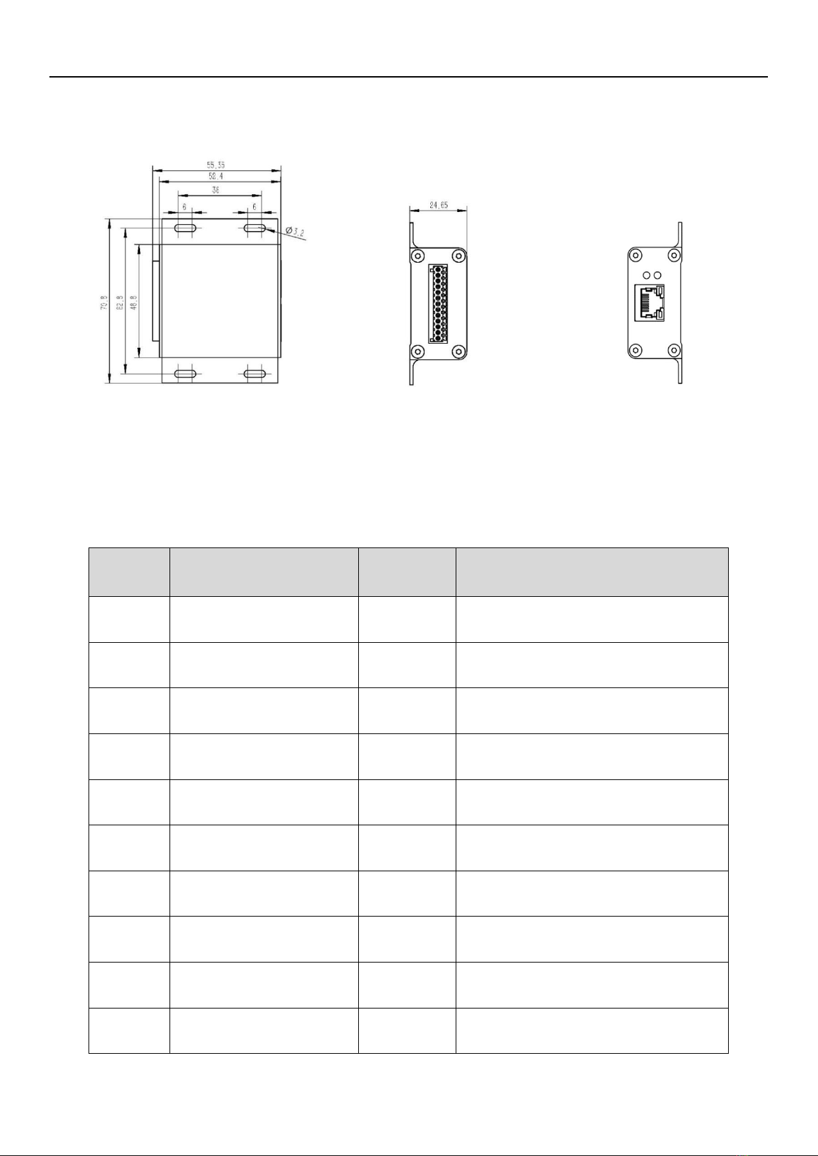
1.1.3 Physical dimensions ..........................................................................................................................6
1.1.4 Cable definition ................................................................................................................................. 8
1.1.5 Packaging information ...................................................................................................................... 8
1.2.1 Product description ........................................................................................................................... 8
1.2.2 Physical dimensions ..........................................................................................................................9
1.2.3 Wiring and indicator light definition ...................................................................................................9
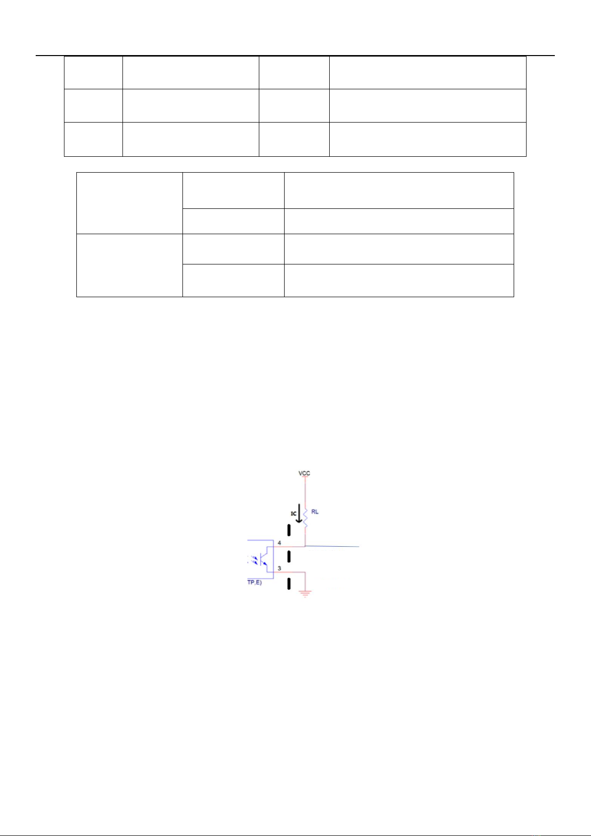
1.2.4 IO protection alarm function ............................................................................................................10
1.2.5 Ethernet bus communication port ...................................................................................................10
2 Precautions for use .......................................................................................................................................11
2.1 Sensor overload protection ....................................................................................................................11
2.1.1 Calculation of the total torque during use .......................................................................................11
2.1.2 Robot emergency stop IO control ...................................................................................................12
2.1.3 Setting of the overload protection threshold ...................................................................................12
2.2 Sensor and robotic arm connection .......................................................................................................13
3 Warranty ....................................................................................................................................................... 13
3.1 Product warranty ....................................................................................................................................13
3.2 Disclaimer .............................................................................................................................................. 14
4 Installation .....................................................................................................................................................14
4.1 Tools and accessories ...........................................................................................................................14
4.2 Mechanical structure installation ........................................................................................................... 15
4.3 Electrical cable installation .................................................................................................................... 17
4.4 IO protection wiring ................................................................................................................................18
4.4.1 Robot emergency stop IO wiring (NPN, no-load IO)......................................................................19
4.4.2 Robot protective stop wiring (NPN, no-load IO) ............................................................................. 19
4.4.3 Setting and enabling of the protection mode of the robot .............................................................. 20
5 Host demonstration software ....................................................................................................................... 21
5.1 Ethernet-based host demonstration software ....................................................................................... 21

Hypersen Technologies Co., Ltd. HPS-FT-USER V1.8
4/38
5.1.1 Ethernet connection steps .............................................................................................................. 21
5.1.2 Filtering and coordinate system conversion functions ................................................................... 23
5.1.3 Port setting ...................................................................................................................................... 24
5.1.4 Save data ........................................................................................................................................ 25
5.1.5 IO alarm function (version 1.9.5 or above) ..................................................................................... 26
5.1.6 One-time acquisition mode function ............................................................................................... 27
5.1.7 Crosstalk compensation function ....................................................................................................27
5.1.8 Overload information receiving function ......................................................................................... 28
5.1.9 Voltage check function ....................................................................................................................28
5.2 RS485 interface–based host software .................................................................................................. 29
5.2.1 RS485 connection ...........................................................................................................................29
5.2.2 Filter .................................................................................................................................................30
5.2.3 One-time acquisition mode function ............................................................................................... 31
5.2.3 Crosstalk compensation function ....................................................................................................31
5.2.4 Overload information receiving function ......................................................................................... 31
5.2.5 Voltage check function ....................................................................................................................31
5.2.6 Baud rate setting ............................................................................................................................. 31
6 Host monitoring software ..............................................................................................................................32
6.1. Host demonstration software connection steps ................................................................................... 32
7 Firmware update software ............................................................................................................................34
7.1. Sensor firmware update ....................................................................................................................... 34
7.2. Ethernet firmware update ..................................................................................................................... 34
8 Troubleshooting ............................................................................................................................................35
8.1 Ethernet adapter failure ......................................................................................................................... 35
Revision history ............................................................................................................................................... 37

Hypersen Technologies Co., Ltd. HPS-FT-USER V1.8
5/38
1 Product introduction
1.1 Sensor introduction
1.1.1 Introduction
The HPS-FT series sensors are high-performance digital 6-axis force torque sensors, which can precisely
measure the force and torque components along the three-dimensional coordinate system axes X, Y and Z.
Thanks to a structure with good durability and a high overload withstanding capacity, the strain gauge can
withstand several times safety overload when working.
Compared to traditional structure, the HPS-FT series sensor has a higher signal-to-noise ratio and sensitivity.
The integrated temperature compensation algorithm significantly reduces the temperature drift of the sensor
due to temperature change. The product can measure the six components of a force: Fx, Fy, Fz, Mx, My and
Mz, in real time with high precision. Besides, the integrated professional compensation algorithm ensures a
high measurement linearity and extremely low crosstalk.
1.1.2 Product features
Measure the force and torque along the axes X, Y and Z quickly and precisely
—High resolution
—High signal-to-noise ratio
—Waterproof and dustproof design (IP65)
—High anti-overload capacity
—Compact design for easy integration
A fully integrated compact structure, which includes:
—an anodized aerospace aluminum housing (HPS-FT060E)
—a stainless steel housing (HPS-FT060S)
—a highly sensitive elastic piece and strain gauge
—a high-precision ACD conversion circuit
—a high performance embedded microprocessor
—advanced embedded data processing, filtering and decoupling algorithms
—a high-speed RS-485 bus port
—EtherCAT and Ethernet adapters

Hypersen Technologies Co., Ltd. HPS-FT-USER V1.8
6/38
1.1.3 Physical dimensions
HPS-FT060E/FT060S dimension diagram
Flange adapter dimension diagram to install HPS-FT060E/FT060S on Cobots

Hypersen Technologies Co., Ltd. HPS-FT-USER V1.8
7/38
HPS-FT025 dimension diagrams
HPS-FT120 dimension diagrams

Hypersen Technologies Co., Ltd. HPS-FT-USER V1.8
8/38
1.1.4 Cable definition
Cable Color
Signal Name
Signal Type
Description
Red
Positive pole of
power supply
VCC
Connected to +12V–+24V DC
Black
Negative pole of
power supply
GND
Connected to the grounding terminal of power
supply
White
RS-485A
Digital
Connected to terminal A of the RS-485 transceiver
(the “+” terminal)
Green
RS-485B
Digital
Connected to terminal B of the RS-485 transceiver
(the “-” terminal)
Yellow
Shielded cable
SHIELD
Connected to the grounding terminal of the housing
1.1.5 Packaging information
1.2 Ethernet adapter
1.2.1 Product description
The HPS-FT-EN2000-IO adapter is used to convert the RS485 port of the 6-axis force torque sensor into a
100M Ethernet interface, supporting more and simpler command settings. Its data output frequency can
reach up to 2000HZ.
Model
HPS-FT025
HPS-FT060E
HPS-FT060S
HPS-FT120
Sensor size
23(H) x 26.2(D) mm
87(L) x 78(W) x
28.5(H)mm
87(L) x 78(W) x
28.5(H)mm
142(L) x 126(W) x
49.9(H)mm
Sensor weight
28g
255g
465g
1450g
Packaging
box size
312(L) x 196(W) x
62(H)mm
312(L) x 196(W) x
62(H)mm
312(L) x 196(W) x
62(H)mm
310(L) x 290(W) x
80(H)mm

Hypersen Technologies Co., Ltd. HPS-FT-USER V1.8
9/38
1.2.2 Physical dimensions
1.2.3 Wiring and indicator light definition
Port
Number
Signal Name
Signal Type
Description
1
Positive pole of adapter
power supply
VCC
Connected to +12V–+24V DC
2
Negative pole of adapter
power supply
GND
Connected to the grounding terminal of
power supply
3
Adapter shield grounding
terminal
SHIELD
Connected to the grounding terminal of
the housing
4
Positive pole of CH1
sensor power supply
VCC
Connected to positive pole of sensor
power supply (red cable)
5
Negative pole of CH1
sensor power supply
GND
Connected to negative pole of sensor
power supply (black cable)
6
485A of CH1 sensor
Digital
Connected to terminal A of RS-485
interface of the sensor (white cable)
7
485B of CH1 sensor
Digital
Connected to terminal B of the RS-485
interface of the sensor (green cable)
8
Positive pole of CH2
sensor power supply
VCC
Connected to positive pole of sensor
power supply (red cable)
9
Negative pole of CH2
sensor power supply
GND
Connected to negative pole of sensor
power supply (black cable)
10
485A of CH2 sensor
Digital
Connected to terminal A of the RS-485
interface of the sensor (white cable)
Figure 2 Left view of
the adapter
Figure 3 Right view
of the adapter
Figure 1 Top view of
the adapter

Hypersen Technologies Co., Ltd. HPS-FT-USER V1.8
10 /38
11
485B of CH2 sensor
Digital
Connected to terminal B of the RS-485
interface of the sensor (green cable)
12*1
Optocoupler Output
Digital
Output port of optocoupler
13*2
Optocoupler COM port
GND
COM port of optocoupler
Upper indicator light
Lit constantly
Channel 1 sensor communication is normal
Not lit
Channel 1 sensor communication is abnormal
Lower indicator light
Lit constantly
Channel 2 sensor communication is normal
Not lit
Channel 2 sensor communication is abnormal
1.2.4 IO protection alarm function
The alarm signal output (port 12) is a non-powered NPN output port, which needs an external GPIO to
provide drive current. COM port (port 13) and the grounding terminal of the signal are not connected. You
can choose to connect them from the outside or isolate them. It is recommended to use RL and VCC so that
the current IC (collector current) after energizing is controlled to 5mA–40mA. When the output current is
greater than 40mA, it is recommended to add a primary power amplifier at the back to avoid equipment
failure due to excessive current.
1.2.5 Ethernet bus communication port
The Ethernet adapter has a UDP or TCP communication port, a UDP port by default. You can also use a
TCP port by switching the jumper 2 inside the adapter. The default IP is 192.168.1.100, the mask is
255.255.255.0, the gateway is 192.168.1.1, and the port number is 8080. You can use commands to modify
the IP, mask, gateway and port number (port 50000 is the debugging port, which is disabled for users). If
jumper 1 inside the adapter is switched to a different position instead of the default position, all parameters
will be initialized to the default parameters every time the adapter is restarted.
Out port (port 12)
COM port (port 13)

Hypersen Technologies Co., Ltd. HPS-FT-USER V1.8
11 /38
2 Precautions for use
The 6-axis force torque sensor is a high-precision device. You should use the sensor properly. Improper use
may cause permanent damage to the sensor. Before use, please read the user manual carefully.
2.1 Sensor overload protection
Before use, be sure to determine the range of the force and torque to be measured, so that an appropriate
model of the sensor can be used. When using it, be sure to add an overload protection function to the
program or use the IO alarm function of our company's EtherCAT/Ethernet adapter to carry out an overload
emergency stop of the robot. Especially in the early debugging process, the sensor is often subjected to
unexpected forces and torques that exceed the measuring range. Without any overload protection of the
sensor, the sensor can easily be damaged by impacts.
2.1.1 Calculation of the total torque during use
The following is a calculation example of the torque received by the sensor while it is employed. You can use
this method to calculate whether or not the torque received by the sensor is overloaded under a static load.
Calculation example:
Conditions: The distance between the center of gravity of the end effector (the center of gravity can be
estimated with 3D software) and the origin of the sensor (including the distance between the center of the
elastic piece and the sensor’s upper surface, 14.5mm,) is L. The axis X of HPS-FT060E is placed vertically
downward (the maximum measuring range of HPS-FT060E is 15Nm), and the weight of the end effector is
M. Then there will be the following formula: Mg × L ≤ 15Nm (g = 9.8N/kg)
Origin of the sensor
Center of the end effector

Hypersen Technologies Co., Ltd. HPS-FT-USER V1.8
12 /38
Distance from the end effector to the origin
of the sensor (L)
50mm
100mm
200mm
500mm
Maximum weight of the end effector (kg)
30.6kg
16.3kg
7.6kg
3.1kg
The above is only the calculation of the torque received by the sensor under static conditions, and the
dynamic torque will be greater than this value when the robot is moving.
Conclusion: When the sensor is used for the first time, in order to ensure that the torque received by the
sensor during the entire operation process is within the measuring range, the torque of the end effector at
the end of the sensor should be roughly estimated.
2.1.2 Robot emergency stop IO control
You can connect the IO of our company’s EtherCAT/Ethernet adapter to the emergency stop IO of the robot,
and set an appropriate alarm threshold. When the threshold is exceeded, the adapter will use an IO signal to
trigger an emergency stop of the robot so as to prevent damage to the sensor. Considering the response
speed of the robot to the IO signal, the speed of the robot shall not be too fast.
Calculation example:
Conditions: Use the sensor model HPS-FT060E with an Ethernet adapter of 2k fps sampling rate. (The
fastest time for the sensor to trigger the robot’s emergency stop IO ≥0.5ms).
If:
1. T1 = The minimum time for the sensor to trigger the robot’s emergency stop IO: 0.5ms
2. T2 = The total response time of the robotic arm to an IO signal
3. v = The speed of the robotic arm/manipulator when it hits the object: 1m/s
4. L = The robotic arm’s theoretical movement distance during T1 and T2
Then, L=v×(T1+T2)
T2
1ms
5ms
10ms
20ms
50ms
L
1.5mm
5.5mm
10.5mm
20.5mm
50.5mm
Conclusion: The slower the response of the robotic arm to the overload emergency stop IO, the lower speed
at which the robotic arm shall move when the end effector touches the object.
2.1.3 Setting of the overload protection threshold
Either the overload protection threshold set by the program or the IO alarm threshold of the adapter
should be within a reasonable range. It is recommended to set the protection threshold of force and
torque to approximately 1.5 times the maximum for normal use while taking into account the force and
torque generated by the end effector itself. The thresholds should not exceed the measuring range of the
sensor. Besides, you should set the torque protection threshold within the measuring range. Otherwise, the
sensor will be deformed significantly and is inclined to be damaged.

Hypersen Technologies Co., Ltd. HPS-FT-USER V1.8
13 /38
2.2 Sensor and robotic arm connection
Do not mount the sensor directly on the robot flange. An intermediate flange needs to be installed
between the robot mounting flange and the sensor. Connect the side of the sensor marked “XY” to the end
effector, and the other side to the intermediate flange as shown in the figure. Locking pins need to be
installed on both the front and back sides of the sensor to ensure the sensor to be fixed properly.
The sensor needs to be installed as close as possible to the end effector, so that the loss of the
collected force information can be as little as possible. And the end effector should be as lightweight as
possible. When a heavy effector is used, the force detected by the sensor while the robot’s end posture
attitude is changed is the actual force plus the force and torque components of the end effector.
3 Warranty
3.1 Product warranty
The warranty period of HPS-FT series 6-axis force torque sensor is 12 months.
If the new equipment and its components are found to be defective due to manufacturing or poor materials
within 12 months (no more than 15 months if shipping time is taken into account) after being put into service,
Hypersen Technologies Co., Ltd. shall provide necessary spare parts for replacement or repair relevant
parts.
The equipment or components that are replaced or returned to Hypersen Technologies Co., Ltd. are owned
by Hypersen Technologies Co., Ltd.
If the product is not within the warranty period, Hypersen Technologies Co., Ltd. reserves the right to charge
the customer for replacement or repair.
Hypersen Technologies Co., Ltd. is not liable for any injury or loss such as production loss or damage to
other production equipment, which arises from the product found defective beyond the warranty period.

Hypersen Technologies Co., Ltd. HPS-FT-USER V1.8
14 /38
3.2 Disclaimer
If the product defect is caused by improper handling or noncompliance with the relevant information
described in the user manual, the Product Warranty will be void.
Failures arising from the following are not covered by the warranty:
1. installation, wiring or connection to other control equipment not in accordance with industrial
standards or the user manual and the operation precautions manual;
2. the specifications or standards shown in the user manual and data sheet are exceeded when used;
3. this product is used for any purpose other than those specified;
4. the storage way, operation or operating environment is beyond the scopes specified in the user
manual and the product data sheet (e.g., pollution, salt damage, condensation, lightning strike,
unauthorized disassembly, power surge, water ingress, overload, abnormal power supply);
5. product damage due to improper transportation;
6. damage caused by an accident or collision;
7. any non-original genuine part or accessory is installed.
4 Installation
Take the installation of the 6-axis force torque sensor and the EtherNet adapter on a UR robot as an
example.
4.1 Tools and accessories
Sensor and accessories:
1. 6-axis force torque sensor (HPS-FT060E)
2. EtherNet adapter for the 6-axis force torque sensor (HPS-FT-EN2000-I0)
3. EtherNet adapter terminal block
4. 12v DC adapter
5. URCAP software package (optional, only for UR robots)
6. Intermediate flange (optional for collaborative robots)
7. Φ6×10 cylindrical pin (optional for collaborative robots)
8. TAC21-M6-L12 hexagon socket head cap screw (4 Pcs) (optional for collaborative robots)
9. TAC21-M5-L20 hexagon socket head cap screw (4 Pcs) (optional for collaborative robots)
Self-provided:
1.Ethernet cable

Hypersen Technologies Co., Ltd. HPS-FT-USER V1.8
15 /38
4.2 Mechanical structure installation
List of standard torque
Product Model
Location
Screws Used
Standard Torque (N·m)
HPS-FT025
Mounting surface
Class 10.9 M3
1.5–1.7
Operating surface
Class 10.9 M3
1.5–1.7
HPS-FT060E
Mounting surface
Class 10.9 M5
6.5–7.5
Operating surface
Class 10.9 M4
3.5–4

Hypersen Technologies Co., Ltd. HPS-FT-USER V1.8
16 /38
HPS-FT060S
Mounting surface
Class 10.9 M5
6.5–7.5
Operating surface
Class 10.9 M4
3.5–4
HPS-FT120
Mounting surface
Class 10.9 M6
12–14
Operating surface
Class 10.9 M8
32–34
Notes:
1. When installing the screws, you need to use spring washers and flat washers, and
a small amount of medium-strength thread glue (as shown in the figure).
2. Loctite 243 medium-strength thread glue is recommended.
Steps:
Make sure that the parts are installed firmly.
Note

Hypersen Technologies Co., Ltd. HPS-FT-USER V1.8
17 /38
4.3 Electrical cable installation
Steps:
1. Route the sensor cable from axis 6 to 1 at the end of the robot and fix it.
2. Check the wiring of the sensor and the EtherNet (which are pre-wired before leaving the factory).
3. Wire the 24v power adapter to the power supply port of the EtherNet adapter (which are pre-wired
before leaving the factory) and power it up.
Please check it for confirmation. Incorrect wiring may damage the sensor.
Note
①. If you do not use the provided power adapter, please be sure to use a
12–24V DC power supply and use terminal blocks to protect the wire ends.
There may be a risk of sensor damage arising from this operation. Please
be careful.
Note
Make sure that there is enough room for all joints of the robot to move and take
protective measures to prevent pinch, dragging, abrasion, etc. to avoid cable
damage.
Note

Hypersen Technologies Co., Ltd. HPS-FT-USER V1.8
18 /38
(Optional) 4. Connect the EtherNet adapter to the PC network port with an Ethernet cable, and set the IP
address of the PC network port to 192.168.1.X (the sensor 192.168.1.100 by default). Check whether or not
the sensor is working normally through the “6-axis force torque sensor host”. (Refer to Chapter 8)
5. Connect the EtherNet adapter to the network port of the robot with an Ethernet cable.
4.4 IO protection wiring
The IO port of the adapter is of NPN no-voltage output type. If the IO port of the robot is also of NPN type,
directly connect the OUT port of the adapter to the emergency stop IO port of the robot, and the COM port to
the NPN COM port of the robot. If there is no pull-up resistor inside the IO port of the robot, an external
pull-up resistor is required.
If the IO port of the robot is of PNP type, an external NPN-PNP signal conversion module is required to
convert the NPN signal of the adapter into a PNP signal to be transmitted to the IO port of the robot.
Shielded wire

Hypersen Technologies Co., Ltd. HPS-FT-USER V1.8
19 /38
4.4.1 Robot emergency stop IO wiring (NPN, no-load IO)
4.4.2 Robot protective stop wiring (NPN, no-load IO)

Hypersen Technologies Co., Ltd. HPS-FT-USER V1.8
20 /38
4.4.3 Setting and enabling of the protection mode of the robot
You can set the basic alarm threshold through the host demonstration software, and carry out a simple test
through the host computer software. For details, see 5.1.5. More functions can be implemented by
commands (see the Ethernet data sheet for details of the commands). The commands are listed as follows:
Function Name
Meaning
Example of Setting
ALARM_CLEAR
Clear IO alarm information
<ALARM_CLEAR 0>
ALARM_THRE_VALUE
Set the IO alarm signal threshold
<ALARM_THRE_VALUE 0
200,200,200,10,10,10>
ALARM_ON
Enable sensor IO alarm
<ALARM_ON 0 1>
ALARM_AXIS
Receive the axis information that
triggers the IO alarm
<ALARM_AXIS 0>
ALARM_SET
Manually trigger sensor IO alarm
<ALARM_SET>
ALARM_NORMAL_OPEN
Set the IO alarm port to be constantly
enabled or constantly disabled
<ALARM_NORMAL_OPEN 1>
Example of operation process:
//Set (usually only once)
<ALARM_NORMAL_OPEN 1>//Set IO alarm to be constantly enabled
<ALARM_THRE_VALUE 0 200,200,200,10,10,10>//Set the alarm threshold
<ALARM_ON 0 1>//Enable the alarm function
<ALARM_CLEAR 0>//Reset alarm
<SAVE>//Save settings
//Normal operation process (loop reading or check overload information after an alarm
is triggered)
①The sensor triggers an alarm, and the robot feeds back the alarm information and
stops
②<ALARM_AXIS 0>//Receive the alarm information and make a judgment according to
the return value
③<SINGLE>//Receive the current force value information of the sensor
④<ALARM_ON 0 0>//Temporarily disable the alarm function (otherwise the alarm will be
triggered all the time)
⑤<ALARM_CLEAR 0>//Clear alarm information
⑥The robot stops operating either by manual intervening or performing collision
processing
This manual suits for next models
2
Table of contents
Other Hypersen Accessories manuals
Popular Accessories manuals by other brands

ELRO
ELRO DVC04C manual

NOVAK
NOVAK ROOSTER CRAWLER ESC - BASIC SETUP GUIDE V2... Setup guide

British General
British General Nexus Moulded 822BELL manual

Detcon
Detcon SmartWireless CX Operator's installation and instruction manual

Bircher Reglomat
Bircher Reglomat ENT-R Assembly instructions

ESI
ESI ESP1010e user guide

ROSE DISPLAYS
ROSE DISPLAYS SNAIL ADHESIVE WITH CEILING SLUG installation instructions

Milesight
Milesight WS523 user guide

Philips AVENT
Philips AVENT NIPLETTE manual

TRENDnet
TRENDnet TEG-S24M200F supplementary guide

HB Products
HB Products HBOC quick guide

Baumer
Baumer SmartReflect FNDR 14G6903/S14/IO quick start guide