Hypnotic Concepts SM-6873 User manual

`
Tools needed:
T20 torx bit
T30 torx bit
6mm drill bit
Drill
Needle nose pliers
Crimpers
Remove the upper fairing by sliding the fuel tank flap towards the rider and removing the 2 pushpins.
Remove side-fairings by
removing 3 pushpins
from both sides.
CAN-AM RYKER- 2" Auxiliary Driving Fog Lights Installation Instructions
**Please read thoroughly before proceeding with installation in order to ensure proper fit & functionality**
Page 1 of 9
Slide gas tank flap towards rider
TOOLS NEEDED:
5mm Allen wrench
19mm wrench
19mm socket
(2) 10mm wrenches
Torque wrench
Needle nose pliers
Pin/nail punch
Small Hammer
PARTS LIST:
(2) TricLED waterproof
fog lights
(2) Control Arm Brackets
(2) Fog Light Brackets
(1) Push Button Bracket
(1) Harness with Push Button
(2) 6mm x 35mm bolts
(2) nylon spacers
(2) 6mm x 15mm bolts
(2) 6mm lock nuts
(4) 6mm washers
STEP 1.
STEP 2.
STEP 3.
Remove the front hood
by lifting on the inner
tabs and pulling the
hood down away from
the Ryker.

`
Remove hex nut with 19mm wrench and washer from
the upper ball joint located on the top of the upper
suspension arm on both sides of the RYKER. Set these
aside, you will be reusing both of these.
Before removing the storage compartment,
remove the 2 screws from the front of the
storage compartment and disconnect the USB
power wires from the back of the storage
compartment.
**In picture (1) the control arm brackets are depicted as they should be mounted on the Ryker.**
Attach the fog light brackets to the control arm brackets utilizing provided hardware. Insert a 6mm washer
into the 6mm bolt, hold the brackets together then insert the washer & bolt through the fog light bracket.
Insert the 2nd washer through the end of the bolt on the other side of the control arm bracket then add
the 6mm lock nut & tighten the nut until the brackets are snug but do not tighten completely. You will
need to adjust the angle of the fog lights once installation is completed.
Page 2 of 9
STEP 4.
STEP 3.
STEP 5.
Fog light Bracket
(1)
Left
Right
Handlebars

`
(1) Remove the cooling fin bezel from the fog light & slide it away from the housing.
(2) Guide the fog light wire through the slot in the fog light bracket.
(3) Seat the threads from the fog light housing through the hole in the fog light bracket. Reattach the
cooling fin bezel and hand tighten. Repeat every step for the opposite side.
Attach control arm bracket to the upper control arm and ball joint. Reinstall the factory washer and nut
that you removed in STEP 4 and tighten snug but DO NOT torque to spec.
You will need to adjust the brackets to your liking once install of harness is complete.
Page 3 of 9
STEP 6.
(1)
(2)
(3)
STEP 7.

`
Route the wire for each fog light underneath the bottom of the forward, upper control arm and secure
with zip ties, then continue to route the wire and secure the wires underneath the cross bar with zip
ties.
(1) Use the 1:2 splitter provided & connect the ends of the 2 fog light wires connectors to the splitter.
(2) Next, attach the 38" wire provided in your kit to the single connector of the splitter & begin to route
the wire along the factory wiring harness. The 2 pin connector will continue to follow the factory wiring
harness and will exit where the side fairing was removed.
**Secure the wire with zip ties along the factory wiring harness**
to tighten down the barrel adjuster.
Page 4 of 9
STEP 8.
(1)
(2)
1:2 SPLITTER
STEP 9.

`
The end of the wiring harness has a black push button on it. Route that push button along the factory
wiring harness thru the area where the upper fairing was removed in STEP 2 & follow the steering
column until the push button is past the handlebar.
Remove the top button cover and washer as in picture above.
Page 5 of 9
For the next step you will need the push button handlebar bracket, (2) 6mm x 35mm bolts and (2)
nylon spacers.
The bracket is ambidextrous and can be mounted on either side of the handlebars. Once mounted, the
end of the bracket should sweep forward as in the picture on the left. Once you decide which side you
will be mounting the bracket to, insert the push button thru the bottom of any of the holes then add
the washer on top and twist on the button cover snug. Do not over tighten.
Towards handlebar
Steering Column
Washer
Route the Push Button
STEP 10.
STEP 11.

`
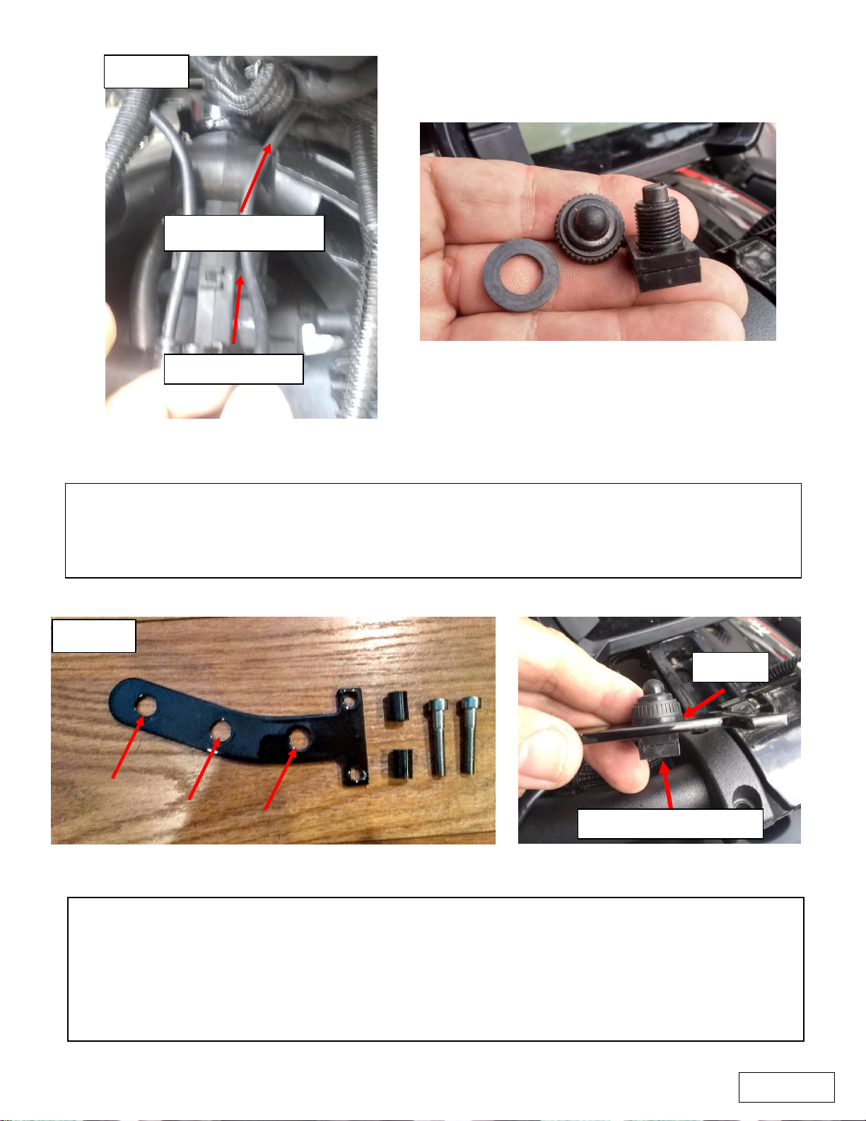
Next, remove the two bolts from the handlebar clamp of the side you will be mounting your push button
bracket to. You will not be reusing these factory bolts.
(1) Place the (2) nylon spacers in the holes where the factory bolts were removed.
(2) Place the push button bracket on top of the nylon spacers and align the bolt holes.
Next, take the (2) 6mm x 35mm bolts provided in your kit and screw them into the holes, use a 5mm Allen
wrench to evenly tighten the bolts down and torque to 9.6 lb-in.
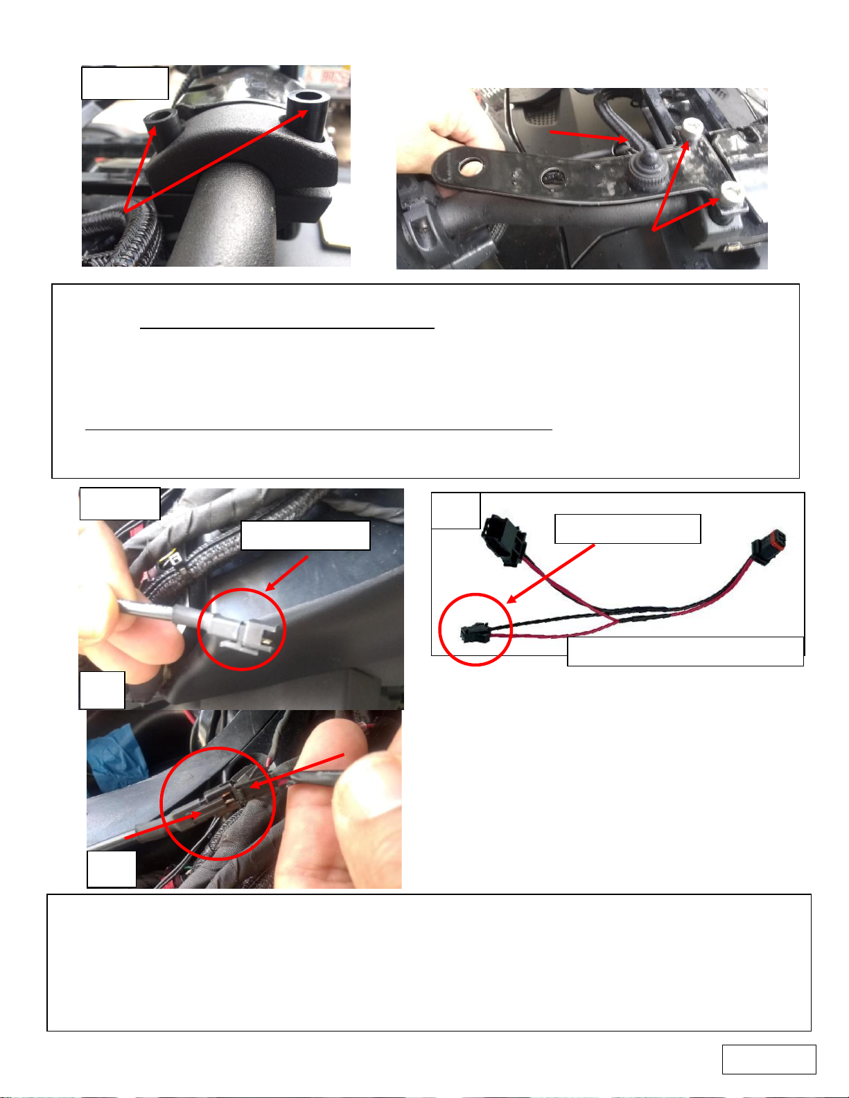
(3) ENSURE THERE IS PLENTY OF SLACK IN THE PUSH BUTTON HARNESS to compensate for the handlebars
moving when making left or right turns. Failure to do so may damage the push button wires from
overstretching.
(1)
(2)
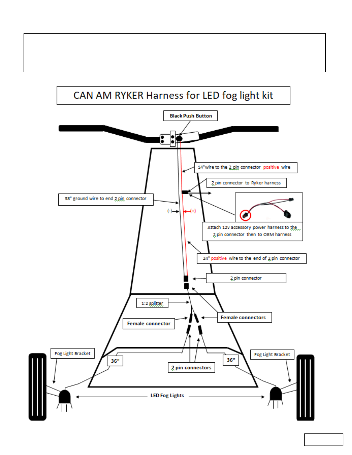
Next, (1) locate the 2 pin connector on the wiring harness (refer to the wiring diagram on the next page).
(2) Take the 12v accessory power harness provided in your kit and connect the female end to the 2 pin
connector.
(3) Make sure that you routed the 2 pin connector along the factory wiring harness and it exits where you
removed the side fairing. Attach the 12v accessory power harness provided in the kit to the 2 pin connector
on the wire harness.
2 pin connector
Female connector
12v accessory power harness
(1)
(2)
(3)
Page 6 of 9
STEP 12.
STEP 13.
(3)

`
Use the diagram below as a reference to continue to the next step.
Attach the 12v accessory power harness provided in the kit to the 2 pin connector on the wire harness &
route the power harness through the hole where the factory harness leads out towards the right fairing
as your looking at the Ryker.
Page 7 of 9

`
Before you replace the storage compartment removed in STEP 3, ensure all wiring is secured and
does not obstruct the installation of the storage compartment.
Replace the side fairings that you removed in STEP 2.
Replace the upper fairing that you removed in STEP 3.
Before replacing the front hood that you removed in STEP 1, ensure that all of the wiring is secured
and not interfering with any moving parts.
(1) Remove the factory accessory connection and locate the 2 pin connector on the wiring harness provided
(refer to the wiring diagram on the next page).
(2) Insert the female connector from the 12v accessory harness into one of the ports on the Ryker that will
hold it in place.
(3) Insert the male factory plug into the 12v accessory wire harness female port.
(4)Insert the male plug from the 12v accessory wire harness and plug it into the port that you removed the
male factory plug from.
(2)
(1)
(3)
(4)
(2)
Plugs into 2 pin connector
Page 8 of 9
Installation of the harness is complete. Before reassembling the fairings, ensure that all cables are secured
and do not obstruct the reassembly process.
*ENSURE THERE IS PLENTY OF SLACK IN THE PUSH BUTTON HARNESS*to compensate for the handlebars
moving when making left or right turns. Failure to do so may damage the push button wires from
overstretching.

`
**Please read instructions thoroughly before proceeding with installation in order to ensure
proper fit and functionality**
Page 9 of 9
After aligning the fog lights brackets and fog lights to your preference, ensure the nuts are torqued to 63
lbf*ft and install a cotter pin in each hole that runs thru the end of the bolt.
(1) Make sure that the hole is not obstructed by the nut.
(2) Take 1 of the 2 cotter pins provided and insert the cotter pin into the hole of the upper ball joint bolt.
(3) To help assist with inserting the cotter pin, use a pin/nail punch and small hammer to light tap the cotter
pin thru the hole.
(4) Use needle nose pliers to bend the cotter pin to ensure that the cotter pin is secured in place.
Perform a functions check of the fog lights by pressing the push button once. This should turn on the lights.
Press the button again and this should turn the fog lights off.
If the fog lights do not turn on and off properly, start over from STEP 1 to ensure the installation was done
properly.
STEP 14
Popular Automobile Accessories manuals by other brands

Spike
Spike 78-2600-R installation instructions

BrandMotion
BrandMotion FLEETWORKS FLTW-7610 installation instructions

SIMUTEC
SIMUTEC SDU V2.0 Installation and user guide

Front Runner
Front Runner PBTT002 installation instructions

HOOKE ROAD
HOOKE ROAD BXG.5004 installation instructions

AEB
AEB ROADFLARE 6 instruction manual

REAL MEDIA SHOP
REAL MEDIA SHOP LDS-VLV40L installation guide

JOSAM
JOSAM homebase 4 Operator's manual

Viridian
Viridian M03-T1C-16A-1P Guidance notes

Metra Electronics
Metra Electronics 99-5841B installation instructions

BD Diesel Performance
BD Diesel Performance 1036703 instructions

DK2
DK2 BCR290 installation manual