Hyster RS45-27CH User manual

OPERATOR'S CAB
PART NO. 4186391 0100 SRM 2043

SAFETY PRECAUTIONS
MAINTENANCE AND REPAIR
• The Service Manuals are updated on a regular basis, but may not reflect recent design changes to the
product. Updated technical service information may be available from your local authorized Hyster®
dealer. Service Manuals provide general guidelines for maintenance and service and are intended for
use by trained and experienced technicians. Failure to properly maintain equipment or to follow
instructions contained in the Service Manual could result in damage to the products, personal injury,
property damage or death.
• When lifting parts or assemblies, make sure all slings, chains, or cables are correctly fastened, and
that the load being lifted is balanced. Make sure the crane, cables, and chains have the capacity to
support the weight of the load.
• Do not lift heavy parts by hand, use a lifting mechanism.
• Wear safety glasses.
• DISCONNECT THE BATTERY CONNECTOR before doing any maintenance or repair on electric lift
trucks. Disconnect the battery ground cable on internal combustion lift trucks.
• Always use correct blocks to prevent the unit from rolling or falling. See HOW TO PUT THE LIFT
TRUCK ON BLOCKS in the Operating Manual or the Periodic Maintenance section.
• Keep the unit clean and the working area clean and orderly.
• Use the correct tools for the job.
• Keep the tools clean and in good condition.
•Always use HYSTER APPROVED parts when making repairs. Replacement parts must meet or
exceed the specifications of the original equipment manufacturer.
• Make sure all nuts, bolts, snap rings, and other fastening devices are removed before using force to
remove parts.
• Always fasten a DO NOT OPERATE tag to the controls of the unit when making repairs, or if the unit
needs repairs.
•Be sure to follow the WARNING and CAUTION notes in the instructions.
• Gasoline, Liquid Petroleum Gas (LPG), Compressed Natural Gas (CNG), and Diesel fuel are
flammable. Be sure to follow the necessary safety precautions when handling these fuels and when
working on these fuel systems.
• Batteries generate flammable gas when they are being charged. Keep fire and sparks away from the
area. Make sure the area is well ventilated.
NOTE: The following symbols and words indicate safety information in this
manual:
WARNING
Indicates a hazardous situation which, if not avoided, could result in death
or serious injury.
CAUTION
Indicates a hazardous situation which, if not avoided, could result in minor
or moderate injury and property damage.
On the lift truck, the WARNING symbol and word are on orange back-
ground. The CAUTION symbol and word are on yellow background.

©2018 HYSTER COMPANY
TABLE OF CONTENTS
Series Code / Model Designation Reference Table ................................................................................................ 1
General .....................................................................................................................................................................1
Description of Operation .........................................................................................................................................1
Cab Structure ...................................................................................................................................................... 1
Remove and Install ..................................................................................................................................................2
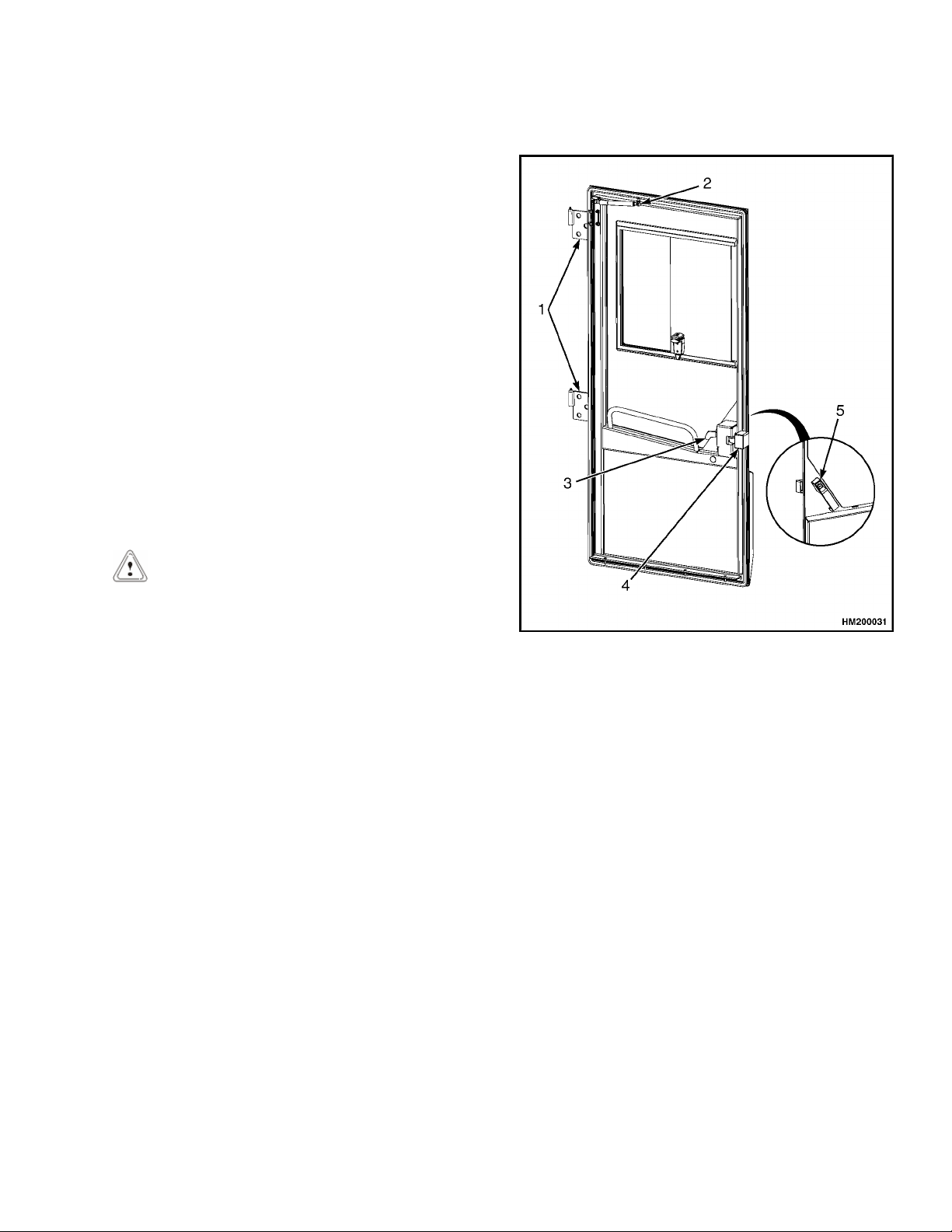
Cab Door Assembly ............................................................................................................................................. 3
Cab Door ...........................................................................................................................................................3
Remove ......................................................................................................................................................... 3
Install ........................................................................................................................................................... 3
Door Hinge ....................................................................................................................................................... 4
Remove ......................................................................................................................................................... 4
Install ........................................................................................................................................................... 4
Door Handle .....................................................................................................................................................4
Remove ......................................................................................................................................................... 4
Install ........................................................................................................................................................... 5
Door Latch ........................................................................................................................................................5
Remove ......................................................................................................................................................... 5
Install ........................................................................................................................................................... 6
Pedals ...................................................................................................................................................................6
Brake and Inching Pedal .................................................................................................................................6
Remove ......................................................................................................................................................... 6
Install ........................................................................................................................................................... 6
Accelerator Pedal and Sensor ......................................................................................................................... 7
Seat Assembly ......................................................................................................................................................7
Seat ...................................................................................................................................................................7
Remove ......................................................................................................................................................... 7
Install ........................................................................................................................................................... 8
Seat Cushion ....................................................................................................................................................8
Remove ......................................................................................................................................................... 8
Install ........................................................................................................................................................... 8
Back Cushion ...................................................................................................................................................9
Remove ......................................................................................................................................................... 9
Install ........................................................................................................................................................... 9
Boot Replacement ............................................................................................................................................9
Seat Suspension Replacement ........................................................................................................................ 9
Suspension Scissor and Shock Absorber Replacement ............................................................................... 10
Remove ....................................................................................................................................................... 10
Install ......................................................................................................................................................... 15
Compressor .................................................................................................................................................... 22
Remove ....................................................................................................................................................... 22
Install ......................................................................................................................................................... 27
Power Assist Armrest ........................................................................................................................................33
Release Cable .................................................................................................................................................33
Remove ....................................................................................................................................................... 33
Install ......................................................................................................................................................... 33
Gas Spring ..................................................................................................................................................... 34
Remove ....................................................................................................................................................... 34
Install ......................................................................................................................................................... 34
Joystick .......................................................................................................................................................... 34
Remove ....................................................................................................................................................... 34
Install ......................................................................................................................................................... 34
Armrest Rocker Switches ..............................................................................................................................35
Table of Contents
i

TABLE OF CONTENTS (Continued)
Remove ....................................................................................................................................................... 35
Install ......................................................................................................................................................... 35
Armrest Top Cover ........................................................................................................................................ 35
Remove ....................................................................................................................................................... 35
Install ......................................................................................................................................................... 35
Cab Fuse Panel ..................................................................................................................................................35
Override Key Switch ..................................................................................................................................... 35
Remove ....................................................................................................................................................... 35
Install ......................................................................................................................................................... 36
12V Power Socket .......................................................................................................................................... 37
Remove ....................................................................................................................................................... 37
Install ......................................................................................................................................................... 37
Climate Control Panel .......................................................................................................................................37
Air Recirculation Control Switch and Air Conditioning Switch ................................................................. 37
Remove ....................................................................................................................................................... 37
Install ......................................................................................................................................................... 37
Heater Control knob (Cable-Operated) ........................................................................................................ 38
Remove ....................................................................................................................................................... 38
Install ......................................................................................................................................................... 38
Information Display .......................................................................................................................................... 38
Remove ...........................................................................................................................................................38
Install ............................................................................................................................................................. 38
Steering Wheel and Column Assembly ............................................................................................................ 39
Steering Column ............................................................................................................................................39
Remove ....................................................................................................................................................... 39
Install ......................................................................................................................................................... 41
Adjustment Handle ....................................................................................................................................... 41
Remove ....................................................................................................................................................... 41
Install ......................................................................................................................................................... 41
Shift Lever and Turn Signal Lever ...............................................................................................................42
Remove ....................................................................................................................................................... 42
Install ......................................................................................................................................................... 42
Window Wipers ..................................................................................................................................................42
Window Wiper Assembly Replacement ........................................................................................................42
Remove ....................................................................................................................................................... 42
Install ......................................................................................................................................................... 42
Window Wiper Motor Replacement ..............................................................................................................42
Front Window Wiper Motor ...................................................................................................................... 42
Remove ................................................................................................................................................... 42
Install ..................................................................................................................................................... 43
Rear Window Wiper Motor Assembly .......................................................................................................... 43
Remove ....................................................................................................................................................... 43
Install ......................................................................................................................................................... 43
Top Window Wiper Motor Assembly ............................................................................................................ 44
Remove ....................................................................................................................................................... 44
Install ......................................................................................................................................................... 44
Window Washer System ................................................................................................................................... 44
Window Washer Reservoir and Pumps ........................................................................................................ 44
Remove ....................................................................................................................................................... 44
Install ......................................................................................................................................................... 45
Window Washer Hoses and Spray Nozzles ..................................................................................................45
Top Window Washer Hose and Spray Nozzle .......................................................................................... 45
Table of Contents
ii

TABLE OF CONTENTS (Continued)
Remove ................................................................................................................................................... 45
Install ..................................................................................................................................................... 45
Rear Window Washer Hose and Spray Nozzle ........................................................................................ 46
Remove ................................................................................................................................................... 46
Install ..................................................................................................................................................... 46
Front Window Washer Hose and Spray Nozzle ....................................................................................... 46
Remove ................................................................................................................................................... 46
Install ..................................................................................................................................................... 46
Window Replacement ........................................................................................................................................47
Cab Windows ................................................................................................................................................. 48
Remove ....................................................................................................................................................... 48
Install ......................................................................................................................................................... 48
Door Window ..................................................................................................................................................48
Remove ....................................................................................................................................................... 48
Install ......................................................................................................................................................... 48
Sliding Window Frame ..................................................................................................................................49
Remove ....................................................................................................................................................... 49
Install ......................................................................................................................................................... 49
Floor Mat ........................................................................................................................................................... 50
Remove ...........................................................................................................................................................50
Install ............................................................................................................................................................. 50
Roof Liner .......................................................................................................................................................... 50
Remove ...........................................................................................................................................................50
Install ............................................................................................................................................................. 51
Accessories ......................................................................................................................................................... 51
Mirror Replacement ...................................................................................................................................... 51
Map Light Replacement ................................................................................................................................51
Interior Fan Replacement .............................................................................................................................51
Sunshade Replacement ................................................................................................................................. 52
Top ..............................................................................................................................................................52
Rear ............................................................................................................................................................ 52
Training Seat ................................................................................................................................................. 52
Field Installation ....................................................................................................................................... 52
Remove ....................................................................................................................................................... 53
Label Replacement ............................................................................................................................................ 53
Checks and Adjustments ...................................................................................................................................... 53
Door Striker Pin Adjustment ............................................................................................................................53
Brake Pedal Adjustment ...................................................................................................................................54
Pedal and Sensor Adjustment for Braking and Inching ................................................................................. 55
Inching Sensor Calibration ...............................................................................................................................56
This section is for the following models:
Table of Contents
iii

"THE
QUALITY
KEEPERS"
HYSTER
APPROVED
PARTS

Series Code / Model Designation Reference Table
This table consist of the following Series Codes used
in this manual.
Series Code Model Designation Europe Model Designation America
A404 RS45-27CH, RS45-31CH RS45-27CH, RS45-31CH
General
This SRM describes the functions of the cab and the
replacement instructions for the cab components.
See Figure 1. Some of the described components are
options that may not be present on each cab. The
operation of the various switches and controls can
be found in the Operating Manual.
The description and repair instructions for the
heater assembly are in Cab Heater and Air
Conditioner 0100SRM2044.
The remove and replace instructions for the cab as
an assembly are in the Frame and Main
Components 0100SRM2042.
Information on systems that are related to the cab
can be found in the SRM's:
•Electrical System 2200SRM2052
•Brake System 1800SRM2048
•Steering System 1600SRM2047
•Diagrams 8000SRM2058
Description of Operation
CAB STRUCTURE
The cab frame is a welded structure. The overhead
guard is an integral part of the cab frame. See
Figure 1. In order to maintain maximum overhead
protection do not make changes to the cab frame
and integrated overhead guard.
0100 SRM 2043 Series Code / Model Designation Reference Table
1

1. HEATER SECTION
2. ACCELERATOR PEDAL
3. BRAKE PEDAL
4. INCHING PEDAL
5. STEERING COLUMN
6. FRONT WIPER
7. CLIMATE PANEL
8. INFORMATION DISPLAY
9. LLMS INDICATOR
10. INTEGRATED OVERHEAD GUARD
11. ARMREST
12. TOP WIPER
13. AIR CONDITIONING ASSEMBLY
14. SEAT
15. REAR WIPER
16. E-CONSOLE
17. WINDOW WASHER FLUID RESERVOIR
Figure 1. Operator's Cab
Description of Operation 0100 SRM 2043
2

Remove and Install
Before making any repairs to the lift truck,
complete the following procedures:
•Place the lift truck on a solid, level surface.
•Retract and lower the boom completely.
•Place the shift lever in NEUTRAL.
•Apply the parking brake.
•Shut down the engine.
CAB DOOR ASSEMBLY
Cab Door
Remove
1. Open the sliding window.
2. Detach the gas spring.
3. Open the cab door as far as possible and
position the door at a 90° angle to the frame.
CAUTION
Use caution when lifting the cab door to avoid
damage to the cab frame.
4. Attach two lifting straps through the sliding
window opening. Place a cushion between the
sliding window frame and the lifting straps to
prevent damage.
1. DOOR HINGE
2. GAS SPRING
3. INNER DOOR HANDLE
4. STRIKER PIN
5. OUTER DOOR HANDLE
Figure 2. Cab Door
5. Lift the cab door out of the cab door hinges. See
Figure 2.
6. Move the cab door away from the lift truck and
place it on the ground.
7. Close the sliding window.
Install
1. Open the sliding window.
2. Attach two lifting straps through the sliding
window opening. Place a cushion between the
sliding window frame and the lifting straps to
prevent damage.
0100 SRM 2043 Remove and Install
3

3. Raise the cab door and place it in position
above the hinges.
4. Slowly lower the cab door until the cab door is
seated on the hinges.
5. Remove the lifting strap.
6. Make sure the cab door is moving properly on
the hinges.
7. If necessary, adjust the hinges. See Figure 3.
8. Make sure the door opens and closes correctly
and the locking system functions properly.
9. Attach the gas spring.
Door Hinge
Remove
1. Remove the cab door. See the section Cab Door.
2. Mark the location of the two hinges on the cab
frame.
3. Remove the six capscrews retaining the two
hinges to the cab frame and remove the two
hinges. See Figure 3.
1. DOOR HINGE
2. WASHER
3. CAP SCREW
4. THREAD
Figure 3. Door Hinge
Install
1. Position the two hinges to the cab frame as
marked and install the six capscrews strong
enough to hold the weight of the door, and loose
enough to allow alignment of the hinges.
2. Install the cab door. Refer to the section Cab
Door.
3. Align the door lock with the striker pin and
close the door.
4. Use a nylon hammer to move the lowest hinge
up until it supports the door.
5. Tighten al cap screws for the door hinges to
20 N•m (15 lbf ft).
Door Handle
Remove
1. Remove the plastic plug at the inside of the
door frame. See Figure 4.
Remove and Install 0100 SRM 2043
4

1. CAB DOOR
2. CAP SCREW
3. HEXAGON SOCKET SCREW
4. PLASTIC PLUG
5. LARGE NUT
6. WASHER
7. DOOR LOCKING PLATE
8. DOOR HANDLE
9. RUBBER CUSHION
Figure 4. Door Handle
2. Remove the capscrew and washer that retain
the door handle, through the hole from the
plastic plug.
3. Remove the large nut and washer that retain
the door handle inside the door latch.
4. Remove the door handle and two rubber
cushions.
Install
1. Position the door handle and two rubber
cushions on the door. See Figure 4.
2. Install the washer and large nut inside the door
latch.
3. Install the washer and capscrew through the
hole from the plastic plug.
4. Install the plastic plug at the inside of the door
frame.
5. Make sure the locking system functions
correctly.
Door Latch
Remove
1. Remove the door handle. See Door Handle,
Remove.
2. Remove the cap screws that retain the cover to
the door latch. See Figure 5.
1. LATCH COVER
2. NUT
3. WASHER
4. CAP SCREW
5. DOOR LATCH
6. DOOR HANDLE
7. BOLT
8. DOOR LATCH HOUSING
Figure 5. Door Latch
3. Remove the nuts that retain the door latch to
the door latch housing.
4. Remove the door latch from the housing.
5. Remove the bolts.
0100 SRM 2043 Remove and Install
5

Install
1. Insert the bolts in the door latch housing.
2. Install the door latch and install the nuts.
3. Install the cap screw and washer that retain
the cover to the door latch.
4. Install the door handle. See Door Handle,
Install.
5. Make sure the locking system functions
correctly.
PEDALS
Brake and Inching Pedal
Remove
1. Remove the cover that protects the inch sensor
and switch. See Figure 6.
2. Remove the rod, located under the inching
pedal.
3. Disconnect the rod, located under the brake
pedal.
4. Remove the cap screws, washers, and nuts that
retain the brake pedal and inching pedal
assembly to the bracket at the floor of the cab.
5. Remove the inching and brake pedal assembly.
6. Separate the inching pedal from the brake
pedal and remove the three shims.
7. Remove the two bearings from the inching
pedal.
1. BRAKE PEDAL
2. INCHING PEDAL
3. ROD
4. PROTECTION COVER
5. BEARING
6. SHIMS
7. CAP SCREWS, WASHERS AND NUTS
Figure 6. Brake and Inching Pedals Assembly
Install
1. Install the two bearings on the inching pedal.
See Figure 6.
NOTE: Make sure the three shims are positioned
correctly.
2. Position the three shims and install the inching
pedal to the brake pedal. Check if the roller
under the brake pedal is centered above the
bolt head of the brake valve, adjust number of
shims on each side if needed.
3. Position the inching and brake pedal assembly
between the brackets at the floor of the cab.
4. Install the two cap screws, washers, and nuts
that retain the brake pedal to the bracket at
the floor of the cab.
5. Install the two cap screws, washers, and nuts
that retain the inching pedal to the bracket, at
the floor of the cab.
Remove and Install 0100 SRM 2043
6

6. Connect the rod to the inching pedal.
7. Connect the rod to the brake pedal.
8. Check if adjustments to the inching and brake
pedals are required, and adjust as needed.
Refer to the sections Brake Pedal Adjustment
and Inching Pedal Adjustment.
9. Install the protection cover over the inch sensor
and switch.
Accelerator Pedal and Sensor
1. ACCELERATOR PEDAL
2. CPS04 THROTTLE POSITION
3. IDLE VALIDATION SIGNAL
4. CAP SCREW
Figure 7. Accelerator Pedal
1. Disconnect the connectors for Throttle Position
and Idle Validation. See Figure 7.
2. Remove the three cap screws retaining the
accelerator pedal to the cab floor.
3. Install a new pedal and connect the connectors.
SEAT ASSEMBLY
Seat
Remove
NOTE: Use a lifting device for the removal of the
seat.
NOTE: The ground cable is attached with a
capscrew at the right rear corner of the suspension.
1. Disconnect the battery ground cable.
NOTE: There is one electrical connector on the
mechanical seat. There are two electrical connectors
on the air suspension seat.
2. Disconnect the electrical connector(s).
3. Turn the electrical plug counterclockwise and
disconnect the electrical plug located at the
instrument panel side console.
NOTE: The seat must be positioned completely to
the front to allow access to the two front capscrews
inside the sliding system. The seat must be
positioned completely to the rear to allow access to
the two rear capscrews inside the sliding system.
4. Remove the four capscrews, washers, and nuts
located above the sliding system that retain the
seat to the seat suspension.
5. Remove the seat. See Figure 8.
0100 SRM 2043 Remove and Install
7

1. SEAT CUSHION
2. BACK CUSHION
3. BOOT
4. SEAT SUSPENSION
Figure 8. Seat
Install
NOTE: Use a lifting device to install the seat.
1. Position the seat onto the seat suspension.
NOTE: The seat must be positioned completely to
the front to allow access to the two front capscrews
inside the sliding system. The seat must be
positioned completely to the rear to allow access to
the two rear capscrews inside the sliding system.
2. Install the four capscrews, washers, and nuts
located above the sliding system that retain the
seat to the seat suspension.
3. Connect the electrical plug located at the
instrument panel side console.
NOTE: There is one electrical connector on the
mechanical seat. There are two electrical connectors
on the air suspension seat.
4. Connect the connector(s).
NOTE: The ground cable is attached with the
capscrew at the right rear corner of the suspension.
5. Connect the battery ground cable.
Seat Cushion
Remove
1. Slide the seat forward. See Figure 8.
2. Adjust the steering wheel upward to its
maximum height position.
3. Remove and discard the screw from the front
right side.
4. Remove and discard the three clips from the
cushion front.
5. Slide the seat fully backward.
6. Grip the seat cushion on the front right corner.
7. Lift the seat cushion until the guide block
becomes detached.
8. Rotate the seat cushion clockwise.
9. Lift the cushion upward to detach the front of
the seat cushion.
10. Grip the seat cushion at about the halfway
point toward the rear of the cushion.
NOTE: Increase the lifting force until the rear of
the cushion detaches.
11. Lift the seat cushion from right to left.
12. Cut the cable tie securing the connector block
to the seat cushion.
13. Disconnect the spade connectors from the
connector block.
14. Remove and discard the seat cushion.
Install
1. Feed the cables of the new cushion through the
hole in the armrest bracket.
2. Connect the spade connectors to the connector
block.
Remove and Install 0100 SRM 2043
8

3. Use a cable tie to attach the connector block to
the seat cushion.
4. Locate the rear tab on the underside of the seat
cushion over the rectangular hole in the metal
pan.
5. Apply downward pressure over the tab.
6. Slide the cushion around until the tab is
partially located in the rectangular hole.
7. With the cushion angled at approximately 35°
to 45°, apply a sharp blow to the front of the
seat cushion. The tab will enter the hole with
an audible click.
8. Pull the cushion upward to make sure the
cushion is correctly locked into position.
9. Install three new clips to the cushion front.
10. Install a new screw to the front right side.
Back Cushion
Remove
1. Slide the seat assembly to the maximum
forward position. See Figure 8.
2. If equipped, remove the headrest out of the two
guides.
3. Remove the two guides, located at the top side
of the back cushion, that retain the back
cushion to the back pan.
4. Remove the two screws that retain the back
cushion to the back pan.
5. Remove the back cushion.
Install
1. Position the back cushion.
2. Install the two screws that retain the back
cushion to the back pan.
3. Install the two guides, located at the top side of
the back cushion, that retain the back cushion
to the back pan.
4. If equipped, install the headrest in the two
guides.
5. Reposition the seat assembly to the correct
operating position.
Boot Replacement
1. Remove seat See Seat, Remove.
2. Use a small pry bar to remove the 22 plastic
plugs that retain the boot to the seat
suspension. See Figure 8.
3. Remove the boot.
4. Install the new boot.
5. Install the 22 plastic plugs that retain the boot
to the seat suspension.
Seat Suspension Replacement
1. Remove seat. See Seat, Remove.
2. Remove boot. See Boot, Remove.
3. Remove the four capscrews that retain the seat
suspension to the cab floor. See Figure 8.
4. Remove the seat suspension from the cab floor.
5. Position the new seat suspension onto the cab
floor.
6. Install the four capscrews that retain the seat
suspension to the cab floor.
0100 SRM 2043 Remove and Install
9

Suspension Scissor and Shock Absorber Replacement
Remove
NOTE: Replacement instructions for the air seat
and mechanical seat are similar.
STEP 1.
Remove the seat from the suspension. Refer to
Seat.
STEP 2.
Remove the seat suspension from the cab. Refer
to the section Seat Suspension Replacement.
STEP 3.
Remove the boot. Refer to Boot Replacement.
STEP 4.
Position the suspension on a workbench with
the lower housing facing upward.
STEP 5.
For air seats remove the retaining screws for
the air bladder.
STEP 6.
Using a 9/16” Allen wrench, remove the lower
housing pivot shaft nut.
Remove and Install 0100 SRM 2043
10

STEP 7.
Remove the pivot shaft.
STEP 8.
For mechanical seats: Lift the lower housing
and place the suspension scissor in the highest
raised position.
STEP 9.
For mechanical seats: Lift the rear of the lower
housing while sliding the lower housing
forward to disengage the height adjustment
rollers from the roller channels of the lower
housing.
0100 SRM 2043 Remove and Install
11

STEP 10.
Rotate the rear of the lower housing clockwise
to disengage the front suspension scissor rollers
from the roller channels of the lower housing.
STEP 11.
Remove the lower housing from the suspension.
STEP 12.
For mechanical seats: Remove the tether belts
from the suspension scissor lower pivot tubes.
STEP 13.
Using a 9/16” Allen wrench, remove the upper
housing pivot shaft nut.
Remove and Install 0100 SRM 2043
12

STEP 14.
Remove the pivot shaft.
STEP 15.
Remove the weight indicator tension spring
from the suspension scissor to avoid damage to
the weight indicator tension spring.
STEP 16.
Lift the suspension scissor while sliding the
suspension scissor forward to disengage the
front suspension scissor rollers from the roller
channels of the upper housing.
STEP 17.
For both types: Remove the suspension scissor
from the upper housing and place the
suspension scissor on one side. For air seats:
Remove the bladder.
0100 SRM 2043 Remove and Install
13

STEP 18.
Remove the tether belts from the suspension
scissor upper pivot tubes.
STEP 19.
Remove the rear bearing tubes from the
suspension scissor.
STEP 20.
Remove the front suspension scissor rollers
from the suspension scissor.
STEP 21.
Remove the push-on PAL nut that retains the
upper shock absorber bearing to the suspension
scissor.
Remove and Install 0100 SRM 2043
14
This manual suits for next models
1
Table of contents
Other Hyster Construction Equipment manuals
Popular Construction Equipment manuals by other brands

Mauldin
Mauldin 650 2021 Operation manual

Napa
Napa 791-6021 Operating manual & parts list

CASE CONSTRUCTION
CASE CONSTRUCTION 450DX Operator's manual

Labounty
Labounty CP 80 Safety, operation & maintenance manual

Manitowoc
Manitowoc Shuttlelift CD5515-2 Service and maintenance manual

STARKE ARVID
STARKE ARVID KS ETH 800 user manual

guth
guth RA Series operating manual

Ercolina
Ercolina MB-42 Programming instructions

Husqvarna
Husqvarna LT 8005 Operator's manual

EZG
EZG Grip Hog PM-1AIR owner's manual

Roper Whitney
Roper Whitney MBB 4181 MAGNABEND Operation, parts & maintenance manual

Branch Manager
Branch Manager T1001 OPERATION, MAINTENANCE AND SPARE PARTS MANUAL