manuals.online logo
Brands
  1. Home
  2. •
  3. Brands
  4. •
  5. Hyster
  6. •
  7. Forklift
  8. •
  9. Hyster A216 Operating instructions

Hyster A216 Operating instructions

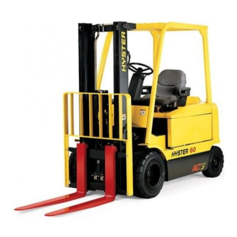
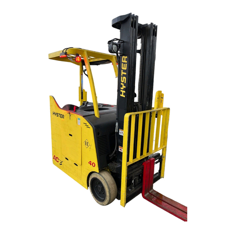
Hyster A216 (J40XM2, J50XM2, J60XM2, J65XM2)
Forklift
PERIODIC
MAINTENANCE
E1.50-1.75XM, E2.00XMS
(E25-40XMS,E25-40XMS
2) [D114];
E2.00-3.20XM (E45-65XM, E45-65XM2) [F108];
J2.00-3.20XM (J40-60XM, J40-60XM2) [A216]
PART NO. 897577 8000 SRM 552
SAFETY PRECAUTIONS
MAINTENANCE AND REPAIR
•When lifting parts or assemblies, make sure all slings, chains, or cables are correctly
fastened, and that the load being lifted is balanced. Make sure the crane, cables, and
chains have the capacity to support the weight of the load.
•Do not lift heavy parts by hand, use a lifting mechanism.
•Wear safety glasses.
•DISCONNECT THE BATTERY CONNECTOR before doing any maintenance or repair
on electric lift trucks. Disconnect the battery ground cable on internal combustion lift
trucks.
•Always use correct blocks to prevent the unit from rolling or falling. See HOW TO PUT
THE LIFT TRUCK ON BLOCKS in the Operating Manual or the Periodic Mainte-
nance section.
•Keep the unit clean and the working area clean and orderly.
•Use the correct tools for the job.
•Keep the tools clean and in good condition.
•Always use HYSTER APPROVED parts when making repairs. Replacement parts
must meet or exceed the specifications of the original equipment manufacturer.
•Make sure all nuts, bolts, snap rings, and other fastening devices are removed before
using force to remove parts.
•Always fasten a DO NOT OPERATE tag to the controls of the unit when making repairs,
or if the unit needs repairs.
•Be sure to follow the WARNING and CAUTION notes in the instructions.
•Gasoline, Liquid Petroleum Gas (LPG), Compressed Natural Gas (CNG), and Diesel fuel
are flammable. Be sure to follow the necessary safety precautions when handling these
fuels and when working on these fuel systems.
•Batteries generate flammable gas when they are being charged. Keep fire and sparks
away from the area. Make sure the area is well ventilated.
NOTE: The following symbols and words indicate safety information in this
manual:
WARNING
Indicates a condition that can cause immediate death or injury!
CAUTION
Indicates a condition that can cause property damage!
Periodic Maintenance Table of Contents
TABLE OF CONTENTS
General ............................................................................................................................................................... 1
Serial Number Data ...................................................................................................................................... 1
How to Move Disabled Lift Truck ................................................................................................................. 1
How to Tow Lift Truck............................................................................................................................... 1
How to Put Lift Truck on Blocks................................................................................................................... 2
How to Raise Drive Tires .......................................................................................................................... 2
How to Raise Steering Tires ..................................................................................................................... 2
Maintenance Schedule....................................................................................................................................... 3
Maintenance Procedures Every 8 Hours or Daily............................................................................................ 11
How to Make Checks With Key OFF............................................................................................................ 11
Tires and Wheels....................................................................................................................................... 11
Forks .......................................................................................................................................................... 12
Adjust..................................................................................................................................................... 12
Remove .................................................................................................................................................. 12
Install..................................................................................................................................................... 13
Forks, Mast, and Lift Chains, Inspect ..................................................................................................... 14
Safety Labels ............................................................................................................................................. 15
Steering Column Latch ............................................................................................................................. 15
Operator Restraint System....................................................................................................................... 15
Battery Restraint System E1.50-3.20XM, E2.00XMS (E25-65XM, E25-65XM2Lift Truck
Models ........................................................................................................................................................ 16
Battery Restraint System J2.00-3.20XM (J40-60XM and J40-60XM2) Lift Truck Models................... 17
Battery ....................................................................................................................................................... 18
Hydraulic System...................................................................................................................................... 19
How to Make Checks With Key ON.............................................................................................................. 20
Gauges, Horn, and Fuses.......................................................................................................................... 20
Steering System ........................................................................................................................................ 20
Service Brakes........................................................................................................................................... 20
Parking Brake ........................................................................................................................................... 20
Control Levers and Pedals........................................................................................................................ 21
Direction and Speed Control Pedals......................................................................................................... 21
Lift System Operation............................................................................................................................... 21
Maintenance Procedures Every 250 Hours or 6 Weeks ................................................................................... 21
Steering Tie Rods........................................................................................................................................... 21
Steering King Pins, Trucks Only .................................................................................................................. 21
Maintenance Procedures Every 500 Hours or 3 Months ................................................................................. 22
Hydraulic Tank Breather .............................................................................................................................. 22
Differential and Speed Reducer.................................................................................................................... 22
Wheel Nut Torques ........................................................................................................................................ 23
Steering Axle Spindles .................................................................................................................................. 23
Steering Tie Rods........................................................................................................................................... 23
Mast................................................................................................................................................................ 23
Lift Chains ..................................................................................................................................................... 24
Wear Check................................................................................................................................................ 24
Forks............................................................................................................................................................... 25
Brake Fluid .................................................................................................................................................... 25
Other Lubrication.......................................................................................................................................... 25
Seat Brake, Models E1.50-3.20XM, E2.00XMS (E25-65XM and E25-65XM2) Only ................................. 26
Electrical Inspection...................................................................................................................................... 26
Contactors.................................................................................................................................................. 26
Motor Brushes ........................................................................................................................................... 27
©2004 HYSTER COMPANY i
Thanks very much for your reading,
Want to get more information,
Please click here, Then get the complete
manual
NOTE:
If there is no response to click on the link above,
please download the PDF document first, and then
click on it.
Have any questions please write to me:
admin@servicemanualperfect.com
Table of Contents Periodic Maintenance
TABLE OF CONTENTS (Continued)
Motor Brushes, General............................................................................................................................ 27
Maintenance Procedures Every 1000 Hours or 6 Months ............................................................................... 42
Lift Chains ..................................................................................................................................................... 42
Forks............................................................................................................................................................... 42
Check Upper and Lower Bearings, Integral Sideshift Carriage................................................................. 42
Maintenance Procedures Every 2000 Hours or Yearly .................................................................................... 43
Hydraulic System .......................................................................................................................................... 43
Change Filter for Hydraulic Oil ............................................................................................................... 43
Change Hydraulic Oil ............................................................................................................................... 44
Differential and Speed Reducer.................................................................................................................... 44
Service Brakes ............................................................................................................................................... 45
Contactors ...................................................................................................................................................... 45
Wheel Bearings.............................................................................................................................................. 45
Steer Wheels, Lubrication ........................................................................................................................ 45
Drive Wheels, Lubrication ........................................................................................................................ 45
Lift Chains ..................................................................................................................................................... 46
Replace Upper and Lower Bearings, Integral Sideshift Carriage .............................................................. 46
Steering Axle.................................................................................................................................................. 46
King Pins and Rod Ends (Steering Cylinders)......................................................................................... 46
Other Lubrication.......................................................................................................................................... 46
Battery Maintenance ......................................................................................................................................... 46
How to Charge Battery.................................................................................................................................. 46
How to Change Battery................................................................................................................................. 48
General....................................................................................................................................................... 48
Change Battery, E1.50-3.20XM, E2.00XMS (E25-65XM and E25-65XM2) Models Only...................... 48
Change J2.00-3.20XM (J40-60XM and J40-60XM2) Battery.................................................................. 51
Lift and Tilt System Leak Check ...................................................................................................................... 53
Lift Cylinders Leak Check ............................................................................................................................ 53
Tilt Cylinders Leak Check ............................................................................................................................ 53
Safety Procedures When Working Near Mast.................................................................................................. 54
Lift Chain Adjustments ..................................................................................................................................... 56
PMT Circuit Check ............................................................................................................................................ 57
Welding Repairs ................................................................................................................................................. 58
Overhead Guard Changes ................................................................................................................................. 58
Wheels and Tire Maintenance........................................................................................................................... 59
Tires and Wheels, E1.50-3.20XM, E2.00XMS (E25-65XM and E25-65XM2) ............................................. 59
Remove Wheels From Lift Truck.............................................................................................................. 59
Remove and Install Tire on Wheel ........................................................................................................... 59
Pneumatic Tires and Wheels J2.00-3.20XM (J40-60XM and J40-60XM2)................................................. 60
Remove Wheels From Lift Truck.............................................................................................................. 60
Remove Wheel From Pneumatic Tire....................................................................................................... 61
Install Wheel in Pneumatic Tire .............................................................................................................. 62
Install Three- or Four-Piece Wheel in Pneumatic Tire........................................................................... 63
Add Air to Tires ......................................................................................................................................... 64
Wheels, Install........................................................................................................................................... 64
Solid Rubber Tires on Pneumatic Wheels .................................................................................................... 65
Remove Wheels From Lift Truck.............................................................................................................. 65
Remove Solid Rubber Tire From Pneumatic Wheel................................................................................ 65
Install Solid Rubber Tire on Pneumatic Wheel ....................................................................................... 67
Wheels, Install........................................................................................................................................... 68
Solid Rubber Tire, Change ............................................................................................................................ 68
ii
Periodic Maintenance Table of Contents
TABLE OF CONTENTS (Continued)
Remove and Install Tire on Wheel ........................................................................................................... 68
Remove Wheel From Tire ......................................................................................................................... 70
Install Wheel in Tire ................................................................................................................................. 71
SIT Tire, Change ........................................................................................................................................... 72
Remove SIT Solid Tire From Wheel......................................................................................................... 73
Install SIT Solid Tire on Wheel ................................................................................................................ 74
Adhesives and Sealants..................................................................................................................................... 75
This section is for the following models:
E1.50-1.75XM, E2.00XMS (E25-40XMS, E25-40XMS2) [D114];
E2.00-3.20XM (E45-65XM, E45-65XM2) [F108];
J2.00-3.20XM (J40-60XM, J40-60XM2)[A216]
iii
"THE
QUALITY
KEEPERS"
HYSTER
APPROVED
PARTS
8000 SRM 552 General
General
WARNING
Do not make repairs or adjustments unless you
have both authorization and training. Repairs
and adjustments that are not correct can make
a dangerous operating condition.
Do not operate a lift truck that needs repairs.
Report the need for repairs immediately. If re-
pair is necessary, put a DO NOT OPERATE tag
in the operator’s area. Remove the key from
the key switch. Disconnect the battery connec-
tor.
CAUTION
Disposal of lubricants and fluids must meet lo-
cal environmental regulations.
Disposal of batteries must meet local environ-
mental regulations.
On lift trucks before XM2, when turning the key
switch to the ON position, the Brush Wear Indicator
and Motor Temperature Indicator will illuminate.
On XM2lift trucks, there is no brush wear indicator,
but the LCD screen will show a status code indicat-
ing that the brushes need replacing as described in
the Operating Manual. Contact your dealer if any
LED Indicators do not illuminate during the check
part of initial lift truck operation.
This section contains a Maintenance Schedule and
the instructions for maintenance and inspection.
The Maintenance Schedule has time intervals for in-
spection, lubrication, and maintenance. The time
intervals are based on a normal operation. A nor-
mal operation is considered to be one 8-hour shift
per day in a relatively clean environment on an im-
proved surface. Multiple shifts, dirty operating con-
ditions, etc., will require a reduction in the recom-
mended time periods in the Maintenance Schedule.
Your dealer for Hyster lift trucks has the equipment
and trained service personnel to do a complete pro-
gram of inspection, lubrication, and maintenance. A
regular program of inspection, lubrication, and main-
tenance will help your lift truck provide more effi-
cient performance and operate for a longer period of
time.
Some users have service personnel and equipment
to do the inspection, lubrication, and maintenance
shown in the Maintenance Schedule. Service Man-
uals are available from your dealer for Hyster lift
trucks to help users who do their own maintenance.
SERIAL NUMBER DATA
The serial number code for the lift truck is on the
Nameplate. The code is also stamped on top of the
rear bulkhead of the frame. It is on the bulkhead
inside the right rear leg of the overhead guard.
HOW TO MOVE DISABLED LIFT TRUCK
How to Tow Lift Truck
WARNING
Use extra caution when towing a lift truck if
any of the following conditions exist:
• Brakes do not operate correctly.
• Steering does not operate correctly.
• Tires are damaged.
• Traction conditions are bad.
• The lift truck must be moved on a steep
grade.
If the steering pump motor does not operate,
steering control of the lift truck can be slow
and difficult. Do NOT tow the lift truck if there
is no power. Poor traction can cause the dis-
abled lift truck or towing vehicle to slide. Steep
grades will require additional brake force to
stop the lift truck.
Never carry a disabled lift truck unless the lift
truck MUST be moved and cannot be towed.
The lift truck used to carry the disabled lift
truck MUST have a rated capacity equal to
or greater than the weight of the disabled
lift truck. The capacity must be for a load
center equal to half the width of the disabled
lift truck. See the Nameplate of the disabled
lift truck for the approximate total weight.
The forks must extend the full width of the
disabled lift truck. Put the weight center of
the disabled lift truck on the load center of the
forks. Do not damage the underside of the lift
truck.
1. The towed lift truck must have an operator.
1
General 8000 SRM 552
2. Raise the carriage and forks approximately
300 mm (12 in.) from the surface. Install a chain
to prevent the carriage and mast channels from
moving.
3. Tow with another lift truck of equal or greater ca-
pacity than the disabled lift truck. Install a load
of approximately half-capacity on the forks of the
lift truck that is being used to tow the disabled
lift truck. The half-capacity load will increase the
traction of the lift truck. Keep the load as low as
possible.
4. Use a towing link made of steel that fastens to
the tow pins in the counterweights of both lift
trucks.
5. Release the parking brake.
6. Tow the lift truck slowly.
HOW TO PUT LIFT TRUCK ON BLOCKS
How to Raise Drive Tires
WARNING
The lift truck must be put on blocks for some
types of maintenance and repair. The removal
of the following assemblies will cause large
changes in the center of gravity: mast, drive
axle, battery, or counterweight. When the lift
truck is put on blocks, put additional blocks in
the following positions to maintain stability:
a. Before removing the mast and drive axle,
put blocks under the counterweight so the
lift truck cannot fall backward.
b. Before removing the counterweight, put
blocks under the mast assembly so the lift
truck cannot fall forward.
The surface must be solid, even, and level when
the lift truck is put on blocks. Make sure that
any blocks used to support the lift truck are
solid, one-piece units.
NOTE: Some lift trucks have lifting eyes. These lift
points can be used to raise the lift truck so that blocks
can be installed.
1. Putblocksoneachside(frontandback)ofthe
steering tires to prevent movement of the lift
truck. See Figure 1.
2. Put the mast in a vertical position. Put a block
under each outer mast channel.
3. Tilt the mast fully forward until the drive tires
are raised from the surface.
4. Put additional blocks under the frame behind the
drive tires.
5. If the hydraulic system will not operate, use a
hydraulic jack under the side of the frame near
the front. Make sure that the jack has a capacity
equal to at least half the weight of the lift truck.
See the Nameplate.
How to Raise Steering Tires
1. Apply the parking brake. Put blocks on both
sides (front and back) of the drive tires to pre-
vent movement of the lift truck. See Figure 1.
2. Use a hydraulic jack to raise the steering tires.
Make sure that the jack has a capacity of at least
2/3 of the total weight of the lift truck as shown
on the Nameplate.
3. Put the jack under the steering axle or frame to
raise the lift truck. Put blocks under the frame
to support the lift truck.
2
8000 SRM 552 Maintenance Schedule
1. DRIVE TIRES 2. STEERING TIRES
Figure1. PutLiftTrucksonBlocks
Maintenance Schedule
The Maintenance Schedule has two time periods.
If the lift truck is operated less than eight hours
each day, do maintenance at the 1-DAY, 6-WEEKS,
3-MONTHS, 6-MONTHS, and 1-YEAR periods. If
the lift truck is operated more than eight hours each
day, do maintenance at the periods shown in hours
(8, 250, 500, 1000, 2000). The approximate locations
of the items indicated in the Maintenance Schedule
are shown in Figure 2, Figure 3, and Figure 4.
The Maintenance Schedule, Table 1, has the max-
imum service intervals for average conditions. In-
spect and lubricate more frequently if the lift truck
operates in dirty or difficult conditions.
3
Maintenance Schedule 8000 SRM 552
Figure 2. E1.50-1.75XM, E2.00XMS (E25-40XM, E25-40XMS2) Maintenance Points
Figure 3. E2.00-3.20XM (E45-65XM, E45-65XM2)MaintenancePoints
4
8000 SRM 552 Maintenance Schedule
NOTE: *TOP OF COUNTERWEIGHT.
Figure 4. J2.00-3.20XM (J40-60XM, J40-60XM2)MaintenancePoints
Table 1. Maintenance Schedule
Item
No. Item 8hr/
1day 250 hr/
6wks 500 hr/
3mo 1000 hr/
6mo
2000
hr/ 1 yr Procedure or
Quantity Specification
Oil Leaks XCheck for leaks
1Tires XCheck condition
13 Forks X X Check condition
12 Mast and Carriage XCheck operation
Safety Labels XReplace as
necessary See Parts Manual
X=Check C=Change L=Lubricate CIL=Check Indicator Light during operation
NOTE 1: Equalization charge is required approximately each month.
NOTE 2: Multipurpose grease with 2 to 4% Molybdenum Disulfide.
NOTE 3: Lubricate lower spindle bearings at 250 hours and upper bearings during assembly.
NOTE 4: Replace the contacts in the hydraulic pump contactor every 1000 hours of operation. Replace the
other contacts in the contactors when the thickness is 30% of a new contact. See the Service Manual for
detailed information.
NOTE: Never use steam to clean electrical parts.
5
Maintenance Schedule 8000 SRM 552
Table 1. Maintenance Schedule (Continued)
Item
No. Item 8hr/
1day 250 hr/
6wks 500 hr/
3mo 1000 hr/
6mo
2000
hr/ 1 yr Procedure or
Quantity Specification
XCheck operation
17 Direction and Speed
Control Lubricate as
necessary Multipurpose
Grease
See NOTE 2
Steering XCheck operation
Gauges, Horn,
Lights, Reverse
Alarm, and Fuses
XCheck operation
XCheck conditionSeat Belt and Seat
Rails CIL
4Hydraulic Oil
(FULL mark)
E1.50-1.75XM,
E2.00XMS (E25-
40XM,
E25-40XMS2)
X C 19 liter (20 qt) 180 to 38 C
(0 to 100 F)
SAE 10W
API SC/CC
4Hydraulic Oil
(FULL mark)
E2.00-3.20XM
(E45-65XM,
E45-65XM2)
X C 23 liter (24 qt) 180 to 38 C
(0 to 100 F)
SAE 10W
API SC/CC
4Hydraulic Oil
(FULL mark)
J2.00-3.20XM
(J40-60XM,
J40-60XM2)
X C 27 liter (29 qt) 180 to 38 C
(0 to 100 F)
SAE 10W
API SC/CC
X
CIL LCheck operation
7Parking Brake
Lubricate
linkage Silicone Spray
Hyster P/N 328388
X=Check C=Change L=Lubricate CIL=Check Indicator Light during operation
NOTE 1: Equalization charge is required approximately each month.
NOTE 2: Multipurpose grease with 2 to 4% Molybdenum Disulfide.
NOTE 3: Lubricate lower spindle bearings at 250 hours and upper bearings during assembly.
NOTE 4: Replace the contacts in the hydraulic pump contactor every 1000 hours of operation. Replace the
other contacts in the contactors when the thickness is 30% of a new contact. See the Service Manual for
detailed information.
NOTE: Never use steam to clean electrical parts.
6
8000 SRM 552 Maintenance Schedule
Table 1. Maintenance Schedule (Continued)
Item
No. Item 8hr/
1day 250 hr/
6wks 500 hr/
3mo 1000 hr/
6mo
2000
hr/ 1 yr Procedure or
Quantity Specification
X X L L Check condition
and lubrication 30W Motor oil
or Hyster Chain
and Cable
Lubricant
(P/N 171350)
11 Lift Chains
X L Check
adjustment and
length
15 Fork Pins and Guides LAs necessary Motor oil
18 Hydraulic Filter C1See Parts Manual
3Motor Brushes CIL XCheck condition See Parts Manual
X X Check operationSee Parts Manual
6Service Brakes
CIL Check condition
8Brake Fluid CIL X0.24 liter
(0.5 pt) SAE J-1703
Seat Brake and
Parking Brake
Adjustment
XAdjust as
necessary Must hold a load
on a 15% grade
16 Wheel Nut Torque
E1.50-1.75XM,
E2.00XMS
(E25-40XM,
E25-40XMS2)
Drive Wheels
(Wheel Bolts)
XCheck torque 332 N•m
(245 lbf ft)
16 Wheel Nut Torque
E1.50-1.75XM,
E2.00XMS
(E25-40XMS,
E25-40XMS2)
Steer Wheels
(Whl. Nuts Pneu.)
XCheck torque 156 N•m
(115 lbf ft)
X=Check C=Change L=Lubricate CIL=Check Indicator Light during operation
NOTE 1: Equalization charge is required approximately each month.
NOTE 2: Multipurpose grease with 2 to 4% Molybdenum Disulfide.
NOTE 3: Lubricate lower spindle bearings at 250 hours and upper bearings during assembly.
NOTE 4: Replace the contacts in the hydraulic pump contactor every 1000 hours of operation. Replace the
other contacts in the contactors when the thickness is 30% of a new contact. See the Service Manual for
detailed information.
NOTE: Never use steam to clean electrical parts.
7
Maintenance Schedule 8000 SRM 552
Table 1. Maintenance Schedule (Continued)
Item
No. Item 8hr/
1day 250 hr/
6wks 500 hr/
3mo 1000 hr/
6mo
2000
hr/ 1 yr Procedure or
Quantity Specification
16 Wheel Nut Torque
E1.50-1.75XM,
E2.00XMS
(E25-40XM,
E25-40XMS2)
Steer Wheel Castle
Nuts (Cushion)
XCheck grease
and tighten to
correct torque
Multipurpose
Grease
See NOTE 2
68 N•m (50 lbf ft)
Initial
3N•m(2lbfft)
Final
16 Wheel Nut Torque
E2.00-3.20XM
(E45-65XM,
E45-65XM2)
Steer Wheel Castle
Nuts (Cushion)
XCheck grease
and tighten to
correct torque
Multipurpose
Grease
See NOTE 2
68 N•m (50 lbf ft)
Initial
3N•m(2lbfft)
Final
16 Wheel Nut Torque
E2.00-3.20XM(E45-
65XM, E45-65XM2)
And J2.00-3.20XM
(J40-60XM,
J40-60XM2)
Drive Wheel
(Wheel Nuts)
XCheck torque 237 to 305 N•m
(175 to 225 lbf ft)
16 Wheel Nut Torque
J2.00-3.20XM
(J40-60XM,
J40-60XM2)
Steer Wheels
XCheck torque 237 to 305 N•m
(175 to 225 lbf ft)
19 Steering Axle
Rod Ends
(Steering Cyl.)
LCheck operation
2Fittings Lubricate as
required
Multipurpose
grease
See NOTE 2
X=Check C=Change L=Lubricate CIL=Check Indicator Light during operation
NOTE 1: Equalization charge is required approximately each month.
NOTE 2: Multipurpose grease with 2 to 4% Molybdenum Disulfide.
NOTE 3: Lubricate lower spindle bearings at 250 hours and upper bearings during assembly.
NOTE 4: Replace the contacts in the hydraulic pump contactor every 1000 hours of operation. Replace the
other contacts in the contactors when the thickness is 30% of a new contact. See the Service Manual for
detailed information.
NOTE: Never use steam to clean electrical parts.
8
8000 SRM 552 Maintenance Schedule
Table 1. Maintenance Schedule (Continued)
Item
No. Item 8hr/
1day 250 hr/
6wks 500 hr/
3mo 1000 hr/
6mo
2000
hr/ 1 yr Procedure or
Quantity Specification
19 Steering Axle
King Pins LCheck operation
2Fittings
See NOTE 3
Lubricate as
required
Multipurpose
grease
See NOTE 2
19 Steering Axle Tie
Rods
E1.50-1.75XM,
E2.00XMS
(E25-40XMS, E25-
40XMS2)
LCheck operation
6Fittings Lubricate as
required
Multipurpose
grease
See NOTE 2
19 Steering Axle Tie
Rods
J2.00-3.20XM
(J40-60XM, J40-
60XM2)
LCheck operation
6Fittings Lubricate as
required
Multipurpose
grease
See NOTE 2
Mast Check condition See NOTE 2
9Pivots L2Fittings Multipurpose
grease
Mast Check
Condition See NOTE 2
10 Sliding Surfaces LAs required Multipurpose
grease
Mast Check
Condition See NOTE 2
12 Sideshift Carriage L4Fittings Multipurpose
grease
Mast Check
Condition
X=Check C=Change L=Lubricate CIL=Check Indicator Light during operation
NOTE 1: Equalization charge is required approximately each month.
NOTE 2: Multipurpose grease with 2 to 4% Molybdenum Disulfide.
NOTE 3: Lubricate lower spindle bearings at 250 hours and upper bearings during assembly.
NOTE 4: Replace the contacts in the hydraulic pump contactor every 1000 hours of operation. Replace the
other contacts in the contactors when the thickness is 30% of a new contact. See the Service Manual for
detailed information.
NOTE: Never use steam to clean electrical parts.
9
Maintenance Schedule 8000 SRM 552
Table 1. Maintenance Schedule (Continued)
Item
No. Item 8hr/
1day 250 hr/
6wks 500 hr/
3mo 1000 hr/
6mo
2000
hr/ 1 yr Procedure or
Quantity Specification
Integral Sideshift
Carriage X C Check wear 2.5 mm (3/32 in.)
or less
12
(Upper/Lower
Bearings) 4Bearings
20 Contactors X C Check conditionSee Parts Manual
See NOTE 4
Hinges, Levers,
Linkage, Pedals Seat
Rails
L L As required Multipurpose
grease
(See NOTE 2)
or Silicone Spray
Hyster P/N 328388
14 Differential/Speed
Reducer
E1.50-1.75XM,
E2.00XMS
(E25-40XM,
E25-40XMS2)
X C 2.9 liter (3.1 qt) Ultr Gear Lube
SAE 80W or
Gear Oil SAE
80W-90 (Chevron)
or equivalent
14 Differential/Speed
Reducer
E2.00-3.20XM
(E45-65XM,
E45-65XM2)
X C 4.2 liter (4.4 qt) Ultr Gear Lube
SAE 80W or
Gear Oil SAE
80W-90 (Chevron)
or equivalent
14 Differential/Speed
Reducer
J2.00-3.20XM
(J40-60XM,
J40-60XM2)
X C 3.7 liter (3.9 qt) Ultr Gear Lube
SAE 80W or
Gear Oil SAE
80W-90 (Chevron)
or equivalent
5Hydraulic Tank
Breather X C Clean or replace See Parts Manual
2Wheel Bearings LAs necessary Multipurpose
grease
See NOTE 2
X=Check C=Change L=Lubricate CIL=Check Indicator Light during operation
NOTE 1: Equalization charge is required approximately each month.
NOTE 2: Multipurpose grease with 2 to 4% Molybdenum Disulfide.
NOTE 3: Lubricate lower spindle bearings at 250 hours and upper bearings during assembly.
NOTE 4: Replace the contacts in the hydraulic pump contactor every 1000 hours of operation. Replace the
other contacts in the contactors when the thickness is 30% of a new contact. See the Service Manual for
detailed information.
NOTE: Never use steam to clean electrical parts.
10
8000 SRM 552 Maintenance Procedures Every 8 Hours or Daily
Table 1. Maintenance Schedule (Continued)
Item
No. Item 8hr/
1day 250 hr/
6wks 500 hr/
3mo 1000 hr/
6mo
2000
hr/ 1 yr Procedure or
Quantity Specification
Seat Plate And Seat
Brake Pivots LUse Silicon Spray
Hyster P/N 328388
Brake Linkage and
Shaft LMultipurpose
grease
See NOTE 2
Hoist and Tilt
Controls XLubricate as
necessary Use Silicon Spray
Hyster P/N 328388
Steering Column Tilt
Mechanism XLubricate as
necessary Use Silicon Spray
Hyster P/N 328388
X=Check C=Change L=Lubricate CIL=Check Indicator Light during operation
NOTE 1: Equalization charge is required approximately each month.
NOTE 2: Multipurpose grease with 2 to 4% Molybdenum Disulfide.
NOTE 3: Lubricate lower spindle bearings at 250 hours and upper bearings during assembly.
NOTE 4: Replace the contacts in the hydraulic pump contactor every 1000 hours of operation. Replace the
other contacts in the contactors when the thickness is 30% of a new contact. See the Service Manual for
detailed information.
NOTE: Never use steam to clean electrical parts.
Maintenance Procedures Every 8 Hours or Daily
HOW TO MAKE CHECKS WITH KEY OFF
Tires and Wheels
WARNING
Air pressure in pneumatic tires can cause tire
and wheel parts to explode. The explosion of
wheel parts can cause serious injury or death.
Remove all of the air from the tires before the
tires are removed from the lift truck.
If the air pressure is less than 80% of the correct
air pressure, the tire must be removed before
air is added. Put the tire in a safety cage when
adding air pressure to the tire. Follow the pro-
cedures described in Add Air to Tires section
in your manual.
When air is added to the tires, use a remote air
chuck. The person adding air must stand to the
side of the safety cage and not in front of it.
Inspectthetiresforwire,rocks,glass,piecesof
metal, holes, cuts, and other damage. See Figure 5.
Remove any object that will cause damage. Check
for loose or missing hardware. Remove any wire
strapping or other material that is wrapped around
the axle.
Make sure the wheel bolts or nuts are tight. Tighten
the wheel bolts or nuts in a cross pattern to the cor-
rect torque value shown in the Maintenance Sched-
ule table.
If the lift truck has pneumatic tires, keep the tires at
the correct air pressure. See the Nameplate. Check
theairpressurewithagaugewhenthetiresarecold.
If it is necessary to add air to a tire that is warm,
check one of the other tires on the same axle and add
air to the tire that has low pressure so the air pres-
sures are equal. The air pressure of the warm tires
must always be equal to or greater than the specifica-
tion for air pressure for cold tires. Check pneumatic
wheels for bent or damaged rims. Check for loose or
missing parts.
11
Maintenance Procedures Every 8 Hours or Daily 8000 SRM 552
CAUTION
Check all wheel bolts or nuts after 2 to 5 hours
of operation: when new lift trucks begin op-
eration and on all lift trucks when the wheels
have been removed and installed. Tighten the
boltsornutsinacrosspatterntothecorrect
torque value shown in the Maintenance Sched-
ule. When the bolts or nuts stay tight for eight
hours, the interval for checking the torque can
be extended to 500 hours.
Tighten the castle nuts of the steer wheel spindles
of these units to 68 N•m (50 lbf ft) while rotating the
wheel in each direction at EACH installation. Loosen
the nuts 1/4 turn. Pull and push at top of wheel to
check for movement (end play). If there is movement,
tighten the castle nuts to 3 N•m (2 lbf ft). Install
the cotter pins at the nearest alignment positions.
Install the hub cap. Additional torque checks are not
required.
1. CHECK FOR DAMAGE (REMOVE NAILS, GLASS, AND OTHER OBJECTS FROM TREAD)
2. MAKE SMOOTH EDGES
3. CHECK TIRE PRESSURE (PNEUMATIC TIRES)
Figure 5. Tires Check
Forks
The identification of a fork is determined by how it
is connected to the carriage. These lift trucks have
hook forks.
Adjust
Hook forks are connected to the carriage by one of
two types of hooks and lock pins. See Figure 6. These
lock pins are installed through the top fork hooks and
fit into slots in the top carriage bar. Adjust the forks
as far apart as possible for maximum support of the
load. Raise the lock pin in each fork to slide the fork
on the carriage bar. Make sure the lock pin is en-
gaged in the carriage bar to lock the fork in position
after making adjustments.
Remove
WARNING
Do not try to lift a fork without a lifting device.
The forks can weigh up to 181.4 kg (400 lb) each.
Slide a hook fork to the fork removal notch on the car-
riage. See Figure 6 and Figure 8. Lower the fork onto
blocks so the bottom hook of the fork moves through
the fork removal notch. See Figure 7. Lower the car-
riage farther so the top hook of the fork is disengaged
from the top carriage bar. Move the carriage away
from the fork, or use a lifting device to move the fork
away from the carriage.
12

This manual suits for next models

4

Other Hyster Forklift manuals

Hyster T5ZAC Operating instructions

Hyster

Hyster T5ZAC Operating instructions

Hyster N177 Operating instructions

Hyster

Hyster N177 Operating instructions

Hyster D174 Operating instructions

Hyster

Hyster D174 Operating instructions

Hyster A244 Operating instructions

Hyster

Hyster A244 Operating instructions

Hyster K007 User manual

Hyster

Hyster K007 User manual

Hyster D114 Operating instructions

Hyster

Hyster D114 Operating instructions

Hyster A935 J1.6-2.0XN Operating instructions

Hyster

Hyster A935 J1.6-2.0XN Operating instructions

Hyster S40XM Manual

Hyster

Hyster S40XM Manual

Hyster MAST N50F Operating instructions

Hyster

Hyster MAST N50F Operating instructions

Hyster D117 Operating instructions

Hyster

Hyster D117 Operating instructions

Hyster W60-80XT User manual

Hyster

Hyster W60-80XT User manual

Hyster C457 Operating instructions

Hyster

Hyster C457 Operating instructions

Hyster E470 Operating instructions

Hyster

Hyster E470 Operating instructions

Hyster B265 Operating instructions

Hyster

Hyster B265 Operating instructions

Hyster C203 Operating instructions

Hyster

Hyster C203 Operating instructions

Hyster B236 Operating instructions

Hyster

Hyster B236 Operating instructions

Hyster G118 User manual

Hyster

Hyster G118 User manual

Hyster E50XM Operating instructions

Hyster

Hyster E50XM Operating instructions

Hyster J007 Operating instructions

Hyster

Hyster J007 Operating instructions

Hyster G108 Operating instructions

Hyster

Hyster G108 Operating instructions

Hyster H8.00-12.00XM Operating instructions

Hyster

Hyster H8.00-12.00XM Operating instructions

Hyster C449 Operating instructions

Hyster

Hyster C449 Operating instructions

Hyster B214 Operating instructions

Hyster

Hyster B214 Operating instructions

Hyster J30XNT User manual

Hyster

Hyster J30XNT User manual

Popular Forklift manuals by other brands

Mitsubishi FG25K Service manual

Mitsubishi

Mitsubishi FG25K Service manual

Jungheinrich EFG 535 operating instructions

Jungheinrich

Jungheinrich EFG 535 operating instructions

Baoli F Series Operation & service manual

Baoli

Baoli F Series Operation & service manual

TMG TMG-PJ45S product manual

TMG

TMG TMG-PJ45S product manual

Kelvin Mini Series MAINTENANCE INSTRUCTIONS MANUAL

Kelvin

Kelvin Mini Series MAINTENANCE INSTRUCTIONS MANUAL

WIFO K90 Series Manual and safety instructions

WIFO

WIFO K90 Series Manual and safety instructions

UniCarriers WLX Series Operator's manual

UniCarriers

UniCarriers WLX Series Operator's manual

PETTIBONE 6036 Owner's/operator's manual

PETTIBONE

PETTIBONE 6036 Owner's/operator's manual

FEELER FD15C manual

FEELER

FEELER FD15C manual

Noblelift PS 30RP Instruction handbook

Noblelift

Noblelift PS 30RP Instruction handbook

Hover-1 My First Forklift Operation manual

Hover-1

Hover-1 My First Forklift Operation manual

EKKO EK20R Service manual

EKKO

EKKO EK20R Service manual

Taylor TX180S Maintenance manual

Taylor

Taylor TX180S Maintenance manual

HANGCHA XC Series Operation and maintenance manual

HANGCHA

HANGCHA XC Series Operation and maintenance manual

Fowit SP50 Operator's manual

Fowit

Fowit SP50 Operator's manual

Jungheinrich ERC 212 operating instructions

Jungheinrich

Jungheinrich ERC 212 operating instructions

Vestil FPU-TN Series instruction manual

Vestil

Vestil FPU-TN Series instruction manual

EP Equipment EPT20-15ET Operation manual

EP Equipment

EP Equipment EPT20-15ET Operation manual

manuals.online logo
manuals.online logoBrands
  • About & Mission
  • Contact us
  • Privacy Policy
  • Terms and Conditions

Copyright 2025 Manuals.Online. All Rights Reserved.