Hyster B60Z User manual

WALKIE HYDRAULIC
SYSTEMS
B60Z [A230]; B80Z [A233]; C60Z [A478];
C80Z [A479]; W60Z [A231]; W65Z [A229];
W80Z [A234]; B60ZAC [B230]; B80ZAC [B233];
C60ZAC [B478]; C80ZAC [B479]
PART NO. 1500201 1900 SRM 964

SAFETY PRECAUTIONS
MAINTENANCE AND REPAIR
•When lifting parts or assemblies, make sure all slings, chains, or cables are correctly fastened, and
that the load being lifted is balanced. Make sure the crane, cables, and chains have the capacity
to support the weight of the load.
•Donotliftheavypartsbyhand,usealiftingmechanism.
•Wear safety glasses.
•DISCONNECT THE BATTERY CONNECTOR before doing any maintenance or repair on electric
lift trucks. Disconnect the battery ground cable on internal combustion lift trucks.
•Always use correct blocks to prevent the unit from rolling or falling. See HOW TO PUT THE LIFT
TRUCK ON BLOCKS in the Operating Manual or the Periodic Maintenance section.
•Keep the unit clean and the working area clean and orderly.
•Use the correct tools for the job.
•Keep the tools clean and in good condition.
•Always use HYSTER APPROVED parts when making repairs. Replacement parts must meet
or exceed the specifications of the original equipment manufacturer.
•Make sure all nuts, bolts, snap rings, and other fastening devices are removed before using force
to remove parts.
•Always fasten a DO NOT OPERATE tag to the controls of the unit when making repairs, or if the
unit needs repairs.
•Be sure to follow the WARNING and CAUTION notes in the instructions.
•Gasoline, Liquid Petroleum Gas (LPG), Compressed Natural Gas (CNG), and Diesel fuel are
flammable. Be sure to follow the necessary safety precautions when handling these fuels and
when working on these fuel systems.
•Batteries generate flammable gas when they are being charged. Keep fire and sparks away from
the area. Make sure the area is well ventilated.
NOTE: The following symbols and words indicate safety information in this
manual:
WARNING
Indicates a condition that can cause immediate death or injury!
CAUTION
Indicates a condition that can cause property damage!
On the lift truck, the WARNING symbol and word are on orange back-
ground. The CAUTION symbol and word are on yellow background.

Walkie Hydraulic Systems Table of Contents
TABLE OF CONTENTS
General ............................................................................................................................................................... 1
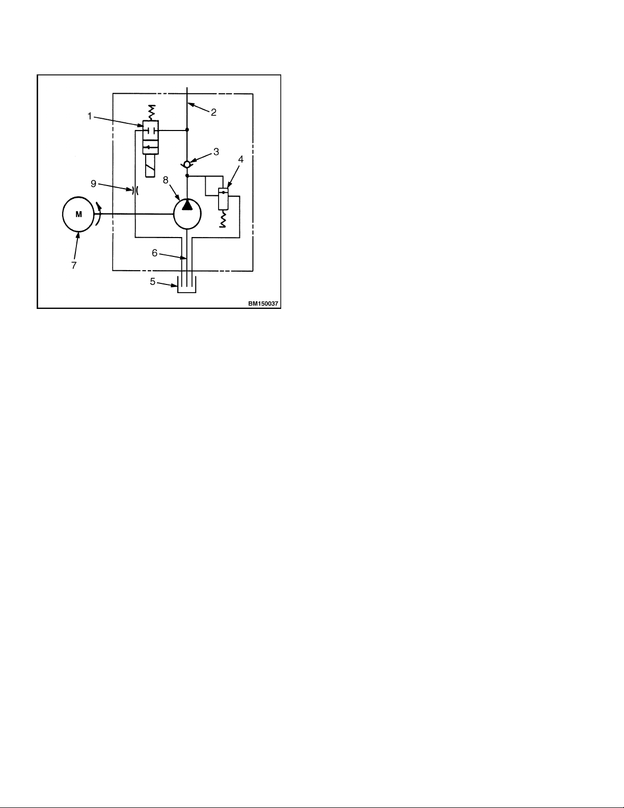
Description of Operation.................................................................................................................................... 1
Lifting a Load................................................................................................................................................. 2
Lowering a Load ............................................................................................................................................ 2
Hydraulic Lines ............................................................................................................................................. 2
Hydraulic Oil ................................................................................................................................................. 2
Clean .............................................................................................................................................................. 5
Sound Level.................................................................................................................................................... 5
Special Precautions............................................................................................................................................ 5
Hydraulic Reservoir........................................................................................................................................... 7
Description ..................................................................................................................................................... 7
Drive Unit Compartment Covers...................................................................................................................... 7
C60Z, C80Z, C60ZAC,andC80Z
AC ................................................................................................................ 7
Remove....................................................................................................................................................... 7
Install......................................................................................................................................................... 7
B60Z, B80Z, B60ZAC,B80Z
AC, W60Z, W65Z, and W80Z............................................................................. 8
Remove....................................................................................................................................................... 8
Install......................................................................................................................................................... 9
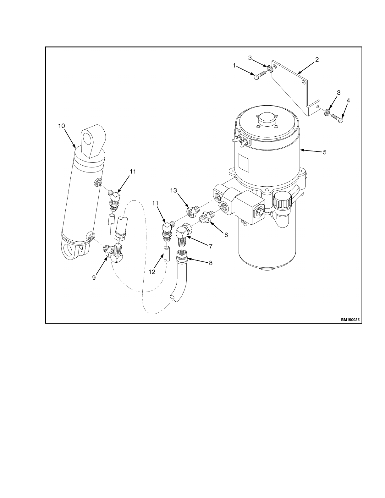
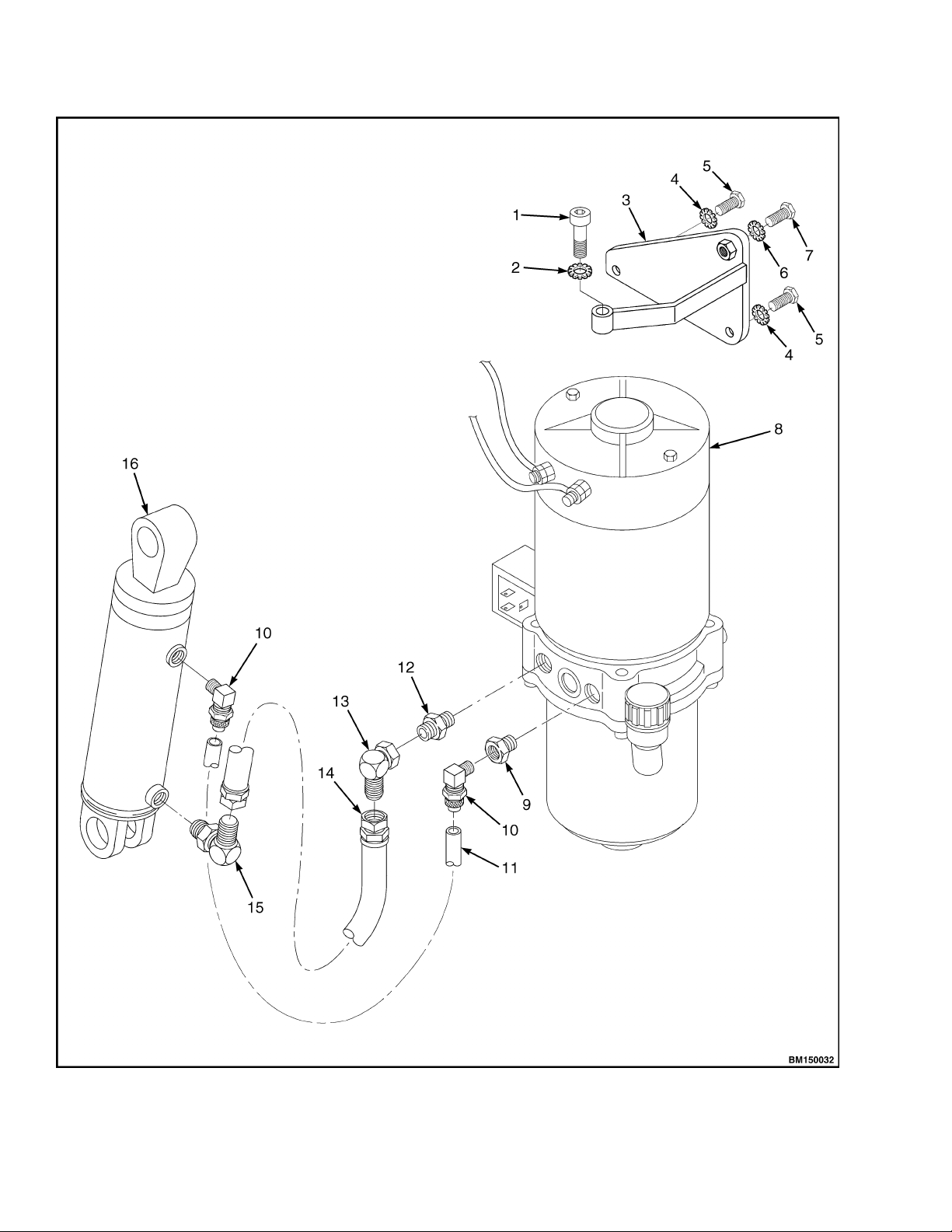
Lift Pump and Motor ......................................................................................................................................... 10
General........................................................................................................................................................... 10
Remove ........................................................................................................................................................... 10
Lift Pump and Motor Assembly................................................................................................................ 10
Disassemble ................................................................................................................................................... 11
Remove Reservoir...................................................................................................................................... 11
Remove Pump Motor................................................................................................................................. 13
B60Z, B60ZAC,C60Z,C60Z
AC, and W60Z............................................................................................ 13
B80Z, B80ZAC,C80Z,C80Z
AC, W65Z, and W80Z................................................................................ 13
Disassemble Pump .................................................................................................................................... 13
B60Z, B60ZAC,C60Z,C60Z
AC, and W60Z............................................................................................ 13
B80Z, B80ZAC,C80Z,C80Z
AC, W65Z, and W80Z................................................................................ 13
Assemble ........................................................................................................................................................ 15
Assemble Pump ......................................................................................................................................... 15
B60Z, B60ZAC,C60Z,C60Z
AC, and W60Z............................................................................................ 15
B80Z, B80ZAC,C80Z,C80Z
AC, W65Z, and W80Z................................................................................ 15
Install Pump Motor................................................................................................................................... 15
Install Reservoir to Pump......................................................................................................................... 16
Install ............................................................................................................................................................. 16
Lift Pump and Motor Assembly................................................................................................................ 16
Valve Repair ....................................................................................................................................................... 17
Lowering Valve .............................................................................................................................................. 17
Remove....................................................................................................................................................... 17
Install......................................................................................................................................................... 17
Relief Valve .................................................................................................................................................... 18
B60Z, B60ZAC,C60Z,C60Z
AC, and W60Z ................................................................................................ 18
Remove .................................................................................................................................................. 18
Install..................................................................................................................................................... 18
B80Z, B80ZAC,C80Z,C80Z
AC, W65Z, and W80Z .................................................................................... 19
Remove .................................................................................................................................................. 19
Install..................................................................................................................................................... 19
Check Valve.................................................................................................................................................... 19
B80Z, B80ZAC,C80Z,C80Z
AC, W65Z, and W80Z .................................................................................... 19
©2008 HYSTER COMPANY i

Table of Contents Walkie Hydraulic Systems
TABLE OF CONTENTS (Continued)
Remove .................................................................................................................................................. 19
Install..................................................................................................................................................... 20
Lift Cylinder....................................................................................................................................................... 20
Remove ........................................................................................................................................................... 20
Disassemble ................................................................................................................................................... 22
Assemble ........................................................................................................................................................ 22
Install ............................................................................................................................................................. 22
Relief Valve Adjustment .................................................................................................................................... 23
Relief Valve Pressure Check ......................................................................................................................... 23
Adjust Relief Valve Pressure......................................................................................................................... 24
B60Z, B60ZAC, C60Z, C60ZAC, and W60Z................................................................................................ 24
B80Z, B80ZAC, C80Z, C80ZAC, W65Z, and W80Z .................................................................................... 25
Troubleshooting.................................................................................................................................................. 26
Lift Assemblies .............................................................................................................................................. 26
Lift Cylinders................................................................................................................................................. 27
Lift Pump and Motor Assembly.................................................................................................................... 28
This section is for the following models:
B60Z [A230];
B80Z [A233];
C60Z [A478];
C80Z [A479];
W60Z [A231];
W65Z [A229];
W80Z [A234];
B60ZAC [B230];
B80ZAC [B233];
C60ZAC [B478];
C80ZAC [B479]
ii

1900 SRM 964 Description of Operation
General
This section covers the troubleshooting and repair
procedures for the hydraulic components on B60Z,
B80Z,B60Z,B80Z
AC, C60Z, C80Z, C60Z, C80ZAC,
W60Z, W65Z, and W80Z lift trucks.
It also includes the remove and install procedures for
the solenoid coil used to activate the lowering valve.
For troubleshooting and repairs of the electrical com-
ponents, see the sections Electrical System 2200
SRM 929, Electrical System 2200 SRM 1052, Elec-
trical System 2200 SRM 1357, or Electrical Sys-
tem 2200 SRM 1287. See the sections Curtis 1297
Transistor Motor Controller 2200 SRM 928, AC
Motor Controller 2200 SRM 1352, or AC Motor
Controller 2200 SRM 1286 for Controller functions.
Description of Operation
The hydraulic system of the B60Z, B80Z, B60Z,
B80ZAC, C60Z, C80Z, C60Z, C80ZAC, W60Z, W65Z,
and W80Z lift trucks includes:
•Reservoir
•Pump
•Check Valve
•Relief Valve
•Lowering Valve
•Lift Cylinder
•Connecting Hoses and Tubes
WARNING
Always wear the proper protective equipment
including eye protection and petroleum-resis-
tant gloves when handling hydraulic oil. Thor-
oughly wash oil from exposed areas of skin as
soon as possible.
Never check for leaks by putting hands on
hydraulic lines or components under pressure.
Hydraulic oil under pressure can be injected
into the skin.
Completely lower forks to relieve hydraulic
pressure before disassembling any part of
the lift pump or disconnecting any hydraulic
hoses.
The hydraulic oil is hot at normal operating
temperatures. Be careful when draining the
oil.
CAUTION
Protect the hydraulic system from dirt and
contaminants when servicing the hydraulic
system.
Never operate the pump without the proper
amount of oil in the hydraulic system. The
operation of the hydraulic pump with low oil
levels will damage the pump.
The reservoir contains the hydraulic fluid necessary
for the operation of the system. It acts as a heat sink
to provide cooling. As the hydraulic oil leaves the
reservoir, it passes through a strainer in the reser-
voir. See Figure 1.
The hydraulic pump provides the flow of the hy-
draulic oil which activates the cylinder.
A check valve allows flow of the hydraulic oil in one
direction only. In this hydraulic system, it prevents
the oil from flowing backwards through the pump.
A relief valve limits maximum system pressure to
protect the hydraulic system components.
The lowering valve is a normally closed valve. When
it opens, hydraulic oil from the lift cylinder is allowed
to return to the reservoir, and the forks lower.
The lift cylinder rod extends to operate the lift link-
ages to raise the forks.
The connecting hoses and tubing connect the various
hydraulic components in the lift truck to complete
the hydraulic circuit. See Figure 2 and Figure 3.
1

Description of Operation 1900 SRM 964
1. LOWERING SOLENOID VALVE
2. TO LIFT CYLINDER
3. CHECK VALVE
4. RELIEF VALVE
5. RESERVOIR
6. INLET LINE
7. PUMP MOTOR
8. LIFT PUMP
9. ORIFICE
Figure 1. Lift Pump and Motor Assembly
Schematic
LIFTING A LOAD
To raise a load, the lift button must be depressed. De-
pressing this switch will activate the lift pump mo-
tor. Torque is transferred to the pump from the mo-
tor through the motor shaft and the coupling.
Hydraulic oil is pumped through the system as
the pump begins to operate. Atmospheric pressure
forces oil into the low pressure area at the pump
inlet. Air, which is drawn into the reservoir through
the breather, displaces the pumped oil, allowing oil
to be sent through the system. See Figure 1.
As oil is pushed out of the pump, it passes through a
one-way check valve to the lift cylinder. The check
valve prevents oil from flowing back to the pump
when lifting ceases, holding the lift cylinder in the
raised position until lowered.
The piston will begin to lift the load when fluid pres-
sure acting against it is high enough to overcome the
weight of the load.
When the piston is fully extended to the end of its
stroke or if the load is too heavy, pressure will con-
tinue to build until the rated pressure needed to op-
erate the relief valve is reached. When this occurs,
the relief valve, which is normally closed, is forced
back against its spring, creating a path for the fluid
to flow back to the reservoir.
Once relief pressure is reached, hydraulic oil will con-
tinue to be diverted from the relief valve to the reser-
voir until the lift button is released, controller time-
out is reached, or electrical power is interrupted.
LOWERING A LOAD
A load is lowered by depressing the lower button.
When the lower button is depressed, electric current
is sent to the normally closed solenoid lowering valve,
which causes it to change position and open a path
for the trapped hydraulic oil to flow from the cylin-
der back to the reservoir.
HYDRAULIC LINES
1. All hydraulic hoses and tubes must be thor-
oughly cleaned before installation.
2. When making repairs, use the least number of
fittings and connections to minimize flow resis-
tance and the possibility of leakage.
HYDRAULIC OIL
The hydraulic oil in the system performs the dual
function of the power transmission and lubrication.
Using the correct fluid is essential to proper system
operation. See the section Periodic Maintenance
8000 SRM 919, Periodic Maintenance 8000 SRM
1032, Periodic Maintenance 8000 SRM 1368, or
Periodic Maintenance 8000 SRM 1298 for the rec-
ommended hydraulic oil.
The hydraulic oil level should be checked first when
troubleshooting lifting problems. Low oil levels may
make it appear that a problem exists with the battery
or hydraulic system.
2

1900 SRM 964 Description of Operation
1. CAPSCREW
2. MOUNTING BRACKET
3. LOCKWASHER
4. CAPSCREW
5. LIFT PUMP AND MOTOR ASSEMBLY
6. ADAPTER
7. ELBOW FITTING
8. HOSE ASSEMBLY
9. FITTING
10. LIFT CYLINDER ASSEMBLY
11. FITTING
12. TUBE ASSEMBLY
13. ADAPTER
Figure 2. Hydraulic System for B60Z, B60ZAC, C60Z, C60ZAC, and W60Z Lift Trucks
3

Description of Operation 1900 SRM 964
Figure 3. Hydraulic System for B80Z, B80ZAC,C80Z,C80Z
AC, W65Z, and W80Z Lift Trucks
4

1900 SRM 964 Special Precautions
Legend for Figure 3
1. SOCKET-HEAD SCREW
2. LOCKWASHER
3. MOUNTING BRACKET
4. LOCKWASHER
5. CAPSCREW
6. LOCKWASHER
7. CAPSCREW
8. LIFT PUMP AND MOTOR ASSEMBLY
9. ADAPTER
10. FITTING
11. TUBE ASSEMBLY
12. ADAPTER
13. ELBOW FITTING
14. HOSE ASSEMBLY
15. ELBOW FITTING
16. LIFT CYLINDER ASSEMBLY
CLEAN
Adhere to the following precautionary steps to en-
sure that the hydraulic system remains clean.
1. Clean the reservoir and pump area to prevent
contaminants from entering the hydraulic sys-
tem.
2. Clean (flush) the entire system when a failure is
encountered to make sure all paint, metal chips,
welding shot, and debris are removed.
3. Filter each change of oil to prevent the introduc-
tion of contaminants into the system.
4. Provide continuous protection from airborne con-
tamination by keeping the breather cap clean
and serviceable.
SOUND LEVEL
Hydraulic system noise may be caused by both im-
properly selected oil and loose or damaged system
components.
• Cavitation - Can be caused by high fluid viscos-
ity, cold fluid temperatures, or a restriction in the
inlet screen or inlet tubing. At startup, low temper-
atures can cause pump noises due to cavitation.
• Aerated Hydraulic Oil - Results in system noise
that is similar to cavitation. Aerated oil is caused
by the ingestion of air through the joints of the in-
let lines and high-velocity discharge lines. Aera-
tion can also be caused by oil discharging above the
fluid level in the hydraulic reservoir. Aerated hy-
draulic oil occurs when air does not have sufficient
time to escape from the fluid while in the reservoir
before recycling through the system.
Special Precautions
WARNING
The capacitor in the transistor controller can
hold an electrical charge after the battery is
disconnected. To prevent an electrical shock
and personal injury, discharge the capacitor
before inspecting or repairing any component
in the drive unit compartment. Wear safety
glasses. Make certain that the battery has
been disconnected.
CAUTION
To avoid controller damage, always disconnect
the battery, discharge the capacitor, and never
put power to the controller while any power
wires are disconnected. Never short any con-
troller terminal or motor terminal to the bat-
tery. Make sure to use proper procedure when
servicing the controller.
1. Verify that the key switch is in the OFF position
and the battery connector is completely discon-
nected.
2. Discharge the capacitors in the controllers by
connecting a 200-ohm, 2-watt resistor across
the controller’s B+ and B terminals. DO NOT
short across the motor controller terminals
withascrewdriverorjumperwire. Removethe
200-ohm, 2-watt resistor before reconnecting the
battery. See Figure 4 or Figure 5.
5

Special Precautions 1900 SRM 964
1. POSITIVE CONNECTION
2. NEGATIVE CONNECTION
3. JUMPER WIRES
4. 200-OHM, 2-WATT RESISTOR
Figure 4. Discharging the Capacitors (B60Z,
B80Z, C60Z, C80Z, W60Z, W65Z, and W80Z)
1. POSITIVE CONNECTION
2. NEGATIVE CONNECTION
3. JUMPER WIRES
4. 200-OHM, 2-WATT RESISTOR
Figure 5. Discharging the Capacitors (B60ZAC,
B80ZAC,C60Z
AC, and C80ZAC)
6

1900 SRM 964 Drive Unit Compartment Covers
Hydraulic Reservoir
DESCRIPTION
The hydraulic reservoir is made of a durable,
translucent plastic that allows the operator to see
how much hydraulic oil is in the reservoir. The
reservoir is clamped to the adapter plate on the
bottom of the pump and motor assembly in the drive
unit compartment. The reservoir has MIN and MAX
marks on the side. With the truck on level surface,
the forks lowered completely, and the oil at room
temperature, the reservoir should be filled to the
MIN mark. See Table 1.
Table 1. Hydraulic Reservoir
Model Reservoir Markings Reservoir Capacity
B60Z, B60ZAC,C60Z,C60Z
AC, and W60Z MIN and MAX MIN: 0.71 liter (0.75 qt)
B80Z, B80ZAC, C80Z, C80ZAC, W65Z, and W80Z MIN and MAX MIN: 0.85 liter (0.90 qt)
Drive Unit Compartment Covers
C60Z, C80Z, C60ZAC, AND C80ZAC
Many procedures will require access to the drive unit
compartment. The drive unit compartment is located
at the front of the truck, in front of the battery and
below the control handle assembly. Two covers must
be removed to access the drive unit compartment.
The covers must be correctly reinstalled to protect
the electrical system and other components housed
in the drive unit compartment. See Figure 6.
Remove
1. Move the lift truck to a safe and level area.
2. Lower the forks completely to relieve pressure
from the hydraulic system.
3. Turn the key switch to the OFF position and dis-
connect battery.
4. Block load wheels to prevent lift truck from mov-
ing. Refer to the section Periodic Maintenance
8000 SRM 1032 or Periodic Maintenance 8000
SRM 1368 - How to Put A Lift Truck on Blocks.
5. Remove the three screws retaining the lower
cover to the truck.
6. Lift the lower cover from the drive unit compart-
ment.
7. Pull the bottom edge on one side of the upper
cover from the drive unit compartment. Con-
tinue pulling around the edge of the cover until
completely free of the truck.
Install
1. Place the top corners of the upper cover into the
retaining clips in the drive unit compartment.
SeeFigure6.
2. Working around each side, bump the cover into
place using the heel of the hand or a rubber ham-
mer.
3. Place the lower cover into the bottom of the drive
unit compartment. Align the clip nuts with the
cover holes.
4. Secure lower cover into place using three screws.
7

Drive Unit Compartment Covers 1900 SRM 964
1. UPPER COVER
2. LOWER COVER 3. CLIP NUT
4. SCREW
Figure 6. Drive Unit Compartment Covers (C60Z, C80Z, C60ZAC, and C80ZAC)
B60Z, B80Z, B60ZAC,B80Z
AC,W60Z,W65Z,
AND W80Z
The drive unit compartment is concealed behind a
molded cover which fits securely around the drive
unit and steer support to the frame. The floormat
fits snugly in the operator platform after the drive
unit cover is installed.
Remove
1. Move the lift truck to a safe and level area.
2. Lower the forks completely to relieve pressure
from the hydraulic system.
3. Turn the key switch to the OFF position and dis-
connect battery.
4. Block load wheels to prevent lift truck from mov-
ing. Refer to the section Periodic Maintenance
8000 SRM 919 or Periodic Maintenance 8000
SRM 1298 - How to Put A Lift Truck on Blocks.
5. Lift the corners of the floormat and pull it out
away from the drive unit. See Figure 7.
6. Reach under the side of the drive unit cover near
thebottomandfindthegripslot. SeeFigure8.
With both hands, pull up and away from the
truck until the bottom of the cover kicks out
from the retaining clips. Repeat this for the
othersideofthecover.Workaroundtheedgeof
the cover until free from the truck.
8

1900 SRM 964 Drive Unit Compartment Covers
Install
1. Make sure the floormat is pulled away from the
drive unit. Place the bottom of the drive unit
cover onto the operator platform and position the
lower edges partially into the lower retaining
clips.
2. Push the top of the cover partially into the upper
retaining clips. DO NOT push either edge of the
cover in completely before starting all edges into
the proper place.
1. FLOORMAT
2. DRIVE UNIT COMPARTMENT COVER
3. FRAME
4. CASTER MOUNTING ACCESS
Figure 7. Floormat (B60Z, B80Z, B60ZAC,
B80ZAC, W60Z, W65Z, and W80Z)
3. When the cover is aligned and started properly,
press the cover completely into the retaining
clips and place the floormat into the operator
platform around the cover.
1. DRIVE UNIT COMPARTMENT COVER
2. RETAINER TABS
3. GRIP SLOT
4. FRAME
Figure 8. Drive Unit Compartment Cover
9

Lift Pump and Motor 1900 SRM 964
Lift Pump and Motor
GENERAL
The lift pump and motor assembly consist of:
•Electric Motor
•Lift Pump
•Lowering Valve
•Relief Valve
•Check Valve
•Reservoir
•Inlet Tube and Strainer
•Breather/Filler Cap
The lift pump and motor assemblies are mechani-
cally joined together as a compact unit, combining
the reservoir, pump, valves, and motor. The lift pump
is located inside the hydraulic reservoir and coupled
to the motor by an adapter plate, coupling, and four
capscrews.
Lift pump and motor assembly servicing is best per-
formed by removing the unit from the truck to a clean
work area.
NOTE: It is not necessary to remove the complete
lift pump and motor assembly to remove the reser-
voir. When removing only the reservoir, see Remove
Reservoir.
REMOVE
Lift Pump and Motor Assembly
WARNING
Always wear the proper protective equipment
including eye protection and petroleum-resis-
tant gloves when handling hydraulic oil. Thor-
oughly wash oil from exposed areas of skin as
soon as possible.
Completely lower forks to relieve hydraulic
pressure before disassembling any part of
the lift pump or disconnecting any hydraulic
hoses.
CAUTION
Make certain the hydraulic cylinder rod is fully
retracted.
Protect the hydraulic system from dirt and
contaminants when servicing the hydraulic
system.
1. Move the lift truck to a safe and level area.
2. Lower the forks completely to relieve pressure
from the hydraulic system.
3. Turn the key switch to the OFF position and dis-
connect battery.
4. Block load wheels to prevent lift truck from
moving. Refer to the section Periodic Mainte-
nance 8000 SRM 919, Periodic Maintenance
8000 SRM 1032, Periodic Maintenance 8000
SRM 1368, or Periodic Maintenance 8000
SRM 1298 - How to Put A Lift Truck on Blocks.
5. Remove the drive unit compartment covers. See
Drive Unit Compartment Covers.
6. Discharge the capacitor. See Special Precau-
tions.
7. Tag and disconnect all power wires and control
wires to the lift pump and motor assembly.
8. Disconnect the hydraulic hoses.
WARNING
Batteries are heavy and can cause personal in-
jury. Use care to avoid injury. DO NOT put
hands, arms, feet, and/or legs between the bat-
tery and a solid object. Make sure the capacity
of the crane and spreader bar is greater than
the weight of the battery. The weight of the
battery is normally shown on the battery case.
The maximum battery weight is shown on the
lift truck nameplate. The spreader bar must
NOT be made of metal or it must have insulated
straps.
9. If necessary, remove the battery. Use a spreader
bar and an overhead lifting device (crane) to re-
move the battery. DO NOT let the battery move
from side to side. Make sure the battery cables
have clearance. See Figure 9.
NOTE: On B60Z, B60ZAC,C60Z,C60Z
AC,andW60Z
lift trucks, it is recommended to connect a piece of
string/rope to the power wires to help guide the wires
back to the controller when reinstalling the lift pump
and motor assembly.
10. Loosen and remove the three capscrews and lock-
washers retaining the lift pump and motor as-
sembly to the frame. Support the lift pump and
motor assembly as the capscrews are being re-
moved. Remove lift pump and motor assembly.
10

1900 SRM 964 Lift Pump and Motor
11. Place lift pump and motor assembly in a vise on
a workbench in an upright position.
1. CRANE
2. SPREADER BAR
3. INSULATOR STRAPS
4. BATTERY
Figure 9. Battery Removal
DISASSEMBLE
Remove Reservoir
1. If the lift pump and motor assembly has not been
previously removed, perform Step 1 through
Step 6 in Remove, Lift Pump and Motor Assem-
bly.
NOTE: On B60Z, B60ZAC, C60Z, C60ZAC, and W60Z
lift trucks, the capscrews that hold the reservoir to
thepumpassemblyalsoholdthemotortothepump
assembly. When the capscrews are removed, the mo-
tor will be resting on the pump assembly. When rein-
serting the capscrews, ensure that the motor is lo-
cated correctly and the coupling is seated properly.
2. Remove the four capscrews retaining the reser-
voir to the lift pump. See Figure 10 or Figure 11.
3. Carefully remove the reservoir from the lift pump
and motor.
4. If removed, place the pump and motor assembly
on a clean drip pan.
5. Remove and inspect the O-ring seal located be-
tween the lift pump assembly and the hydraulic
reservoir. Verify that the O-ring seal is not dam-
aged. Replace as needed.
6. Inspect the inlet strainer. On B80Z, B80ZAC,
C80Z, C80ZAC,W65Z,andW80Zlifttrucks,also
inspect the return strainer. If necessary, remove
the retaining clip to access the screen. Replace
parts that are damaged or cannot be cleaned.
CAUTION
Disposal of lubricants and fluids must meet lo-
cal and environmental regulations.
7. Pour oil from reservoir in a container suitable for
disposal.
CAUTION
If oil is contaminated or excessively dirty, the
entire hydraulic system should be thoroughly
cleaned.
8. Examine the hydraulic reservoir. Inspect the hy-
draulic reservoir for dirt, foreign materials, or
contamination. Clean and flush the hydraulic
reservoir as necessary.
9. Remove the breather/filler cap. Using a small
prybar, separate the top and bottom of the
breather/filler cap. Clean and inspect the
breather element and the flat seal. Replace
parts that are damaged or cannot be cleaned.
Assemble the breather/filler cap.
11

Lift Pump and Motor 1900 SRM 964
Figure 10. Lift Pump and Motor Assembly for B60Z, B60ZAC, C60Z, C60ZAC, and W60Z Lift Trucks
12

1900 SRM 964 Lift Pump and Motor
Legend for Figure 10
1. LIFT PUMP MOTOR
2. COUPLING
3. LIFT PUMP
4. CLAMP
5. TUBE
6. CLAMP
7. STRAINER
8. SCREEN
9. RETAINER
10. O-RING
11. BREATHER/FILLER CAP
12. FLAT SEAL
13. FILLER ELBOW
14. RESERVOIR
15. CAPSCREW
16. WASHER
17. TWO-PIECE CLAMP
18. RELIEF VALVE
19. CAPSCREW
20. WASHER
21. LOWERING VALVE COIL
22. LOWERING VALVE CARTRIDGE
23. O-RING
24. O-RING
25. LOWERING ORIFICE
Remove Pump Motor
B60Z, B60ZAC,C6
0Z, C60ZAC,andW60Z
1. Lift the motor away from the pump assembly.
2. Inspect the motor output shaft, the pump input
shaft, and the coupling. Replace worn or dam-
aged parts.
B80Z, B80ZAC,C
80Z, C80ZAC, W65Z, and W80Z
1. Remove the two capscrews from top of motor.
2. Lift the motor from the pump assembly.
3. Inspect the motor output shaft, the pump input
shaft, and the coupling. Replace worn or dam-
aged parts.
Disassemble Pump
B60Z, B60ZAC,C
60Z, C60ZAC,andW60Z
1. Remove the clamp retaining the inlet tube to the
pump.
2. Remove the inlet tube and strainer by pulling
down and out.
3. Remove the lowering valve. See Lowering Valve,
Remove.
4. Remove the relief valve. See Relief Valve, Re-
move.
B80Z, B80ZAC,C
80Z, C80ZAC, W65Z, and W80Z
1. Tag and identify each tube with their correspond-
ing location.
2. Remove tubes and associated items from the bot-
tom of pump.
3. Remove the lowering valve from pump assembly.
See Lowering Valve, Remove.
4. Remove the check valve from pump assembly.
See Valve Repair, Remove.
5. Remove the relief valve from pump assembly.
See Relief Valve, Remove.
13

Lift Pump and Motor 1900 SRM 964
Figure 11. Lift Pump and Motor Assembly for B80Z, B80ZAC, C80Z, C80ZAC, W65Z, and W80Z Lift
Trucks
14

1900 SRM 964 Lift Pump and Motor
Legend for Figure 11
1. CAPSCREW
2. LIFT PUMP MOTOR
3. ADAPTER PLATE
4. COUPLING
5. TUBE
6. INLET TUBE
7. RETURN TUBE
8. STRAINER
9. CLAMP
10. STRAINER HOUSING
11. SCREEN
12. RETAINER
13. TWO PIECE CLAMP
14. CAPSCREW
15. WASHER
16. RESERVOIR
17. FILLER ELBOW
18. FLAT SEAL
19. BREATHER/FILLER CAP
20. O-RING
21. O-RING
22. LOWERING ORIFICE
23. CAPSCREW
24. WASHER
25. LOWERING VALVE COIL
26. LOWERING VALVE CARTRIDGE
27. O-RING
28. CHECK VALVE
29. CHECK VALVE BALL
30. LIFT PUMP
31. RELIEF VALVE
ASSEMBLE
Assemble Pump
B60Z, B60ZAC,C6
0Z, C60ZAC,andW60Z
1. Clean and lubricate all components using clean
hydraulic oil.
2. Install the lowering valve. See Lowering Valve,
Install.
3. Install the inlet tube and strainer.
4. Install the new clamp.
5. Install the relief valve. See Relief Valve, Install.
B80Z, B80ZAC,C
80Z, C80ZAC, W65Z, and W80Z
1. Clean and lubricate all components using clean
hydraulic oil.
2. Install the relief valve. See Relief Valve, Install.
3. Install the check valve. See Valve Repair, Install.
4. Install the lowering valve. See Lowering Valve,
Install.
5. Install tubes and related items to bottom of pump
as removed.
Install Pump Motor
WARNING
Always wear the proper protective equipment
including eye protection and petroleum-resis-
tant gloves when handling hydraulic oil. Thor-
oughly wash oil from exposed areas of skin as
soon as possible.
CAUTION
Protect the hydraulic system from dirt and
contaminants when servicing the hydraulic
system.
1. Lubricate the motor output shaft and the pump
input shaft with a light coating of Molycote®G-N
paste.
2. Install the coupling on the pump shaft.
3. Align the slot in the motor shaft with the cou-
pling. Lower the motor onto the pump, rotating
the body as necessary to engage the coupling.
4. Use the following procedure that applies to your
lift truck:
a. Align the pump assembly mounting holes
with the holes in the pump motor. Install the
capscrews and tighten to 8 N•m (71 lbf in).
b. Align the pump motor mounting holes with
the holes in the adapter plate. Install the
capscrews and tighten to 8 N•m (71 lbf in).
15

Lift Pump and Motor 1900 SRM 964
Install Reservoir to Pump
NOTE: If only the reservoir has been removed, per-
form Step 3 through Step 7.
1. Place reservoir in an upright position on the
workbench.
2. Install breather/filler cap to reservoir.
NOTE: The reservoir may be filled at this point or it
may be filled after the lift pump and motor assembly
have been installed.
3. Fill the hydraulic reservoir to proper level. See
Hydraulic Reservoir, Table 1.
4. Install O-ring seal on pump assembly. If neces-
sary, use a small amount of grease to hold the
O-ring seal in position.
5. Position lift pump and motor assembly onto the
reservoir.
6. Install two piece clamp to reservoir and pump
assembly.
7. Install four capscrews and torque to 8 N•m
(71 lbf in).
INSTALL
Lift Pump and Motor Assembly
1. Align the lift pump and motor assembly with the
mounting holes in the frame.
2. Apply Loctite®242 to the threads of the mount-
ing capscrews. Install three capscrews with lock-
washers and torque to the proper torque. See
Figure 12.
3. Install hydraulic hoses to lift pump and motor
assembly.
4. Connect power wires and control wires to lift
pump and motor assembly.
A. 6000 LBS CAPACITY B. 8000 LBS CAPACITY
Figure 12. Torque Values
16
This manual suits for next models
21
Table of contents
Other Hyster Industrial Equipment manuals
Popular Industrial Equipment manuals by other brands

Eaton
Eaton SL4-L Series instructions

Allen-Bradley
Allen-Bradley 140G-N-TLH3 Installation

MACHINE SOLUTIONS
MACHINE SOLUTIONS BEAHM Tube Flare 120 user manual

Siemens
Siemens SINUMERIK 840 sl Commissioning manual

Bosch
Bosch Rexroth ActiveMover Assembly instructions

AstroNova
AstroNova TrojanLabel T3-OPX Service guide