Hyundai Seasall U125S User manual


INSTALLATION & OPERATION MANUAL
U125 Series Engines
TABLE OF CONTENTS
TABLE
OF
CONTENTS
PAGE NUMBER
ABOUT THIS MANUAL ………………………………………………………………….....….
SAFETY PRECAUTIONS ……………………………………………………………………..
ENGINE BREAK-IN …………………………………………………………………………….
3
4
5
CHAPTER 1 ENGINE OVERVIEW ………………………………………………………………
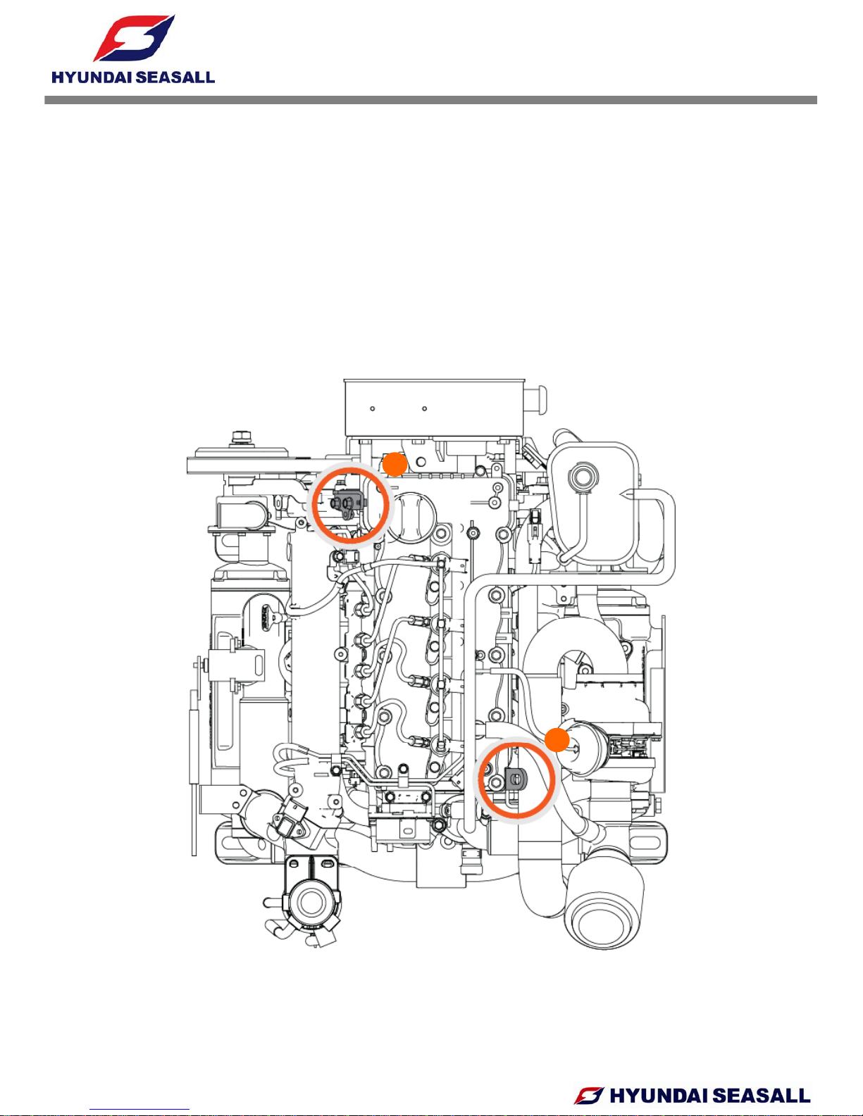
ENGINE COMPONENTS …………………………………………………….……
ENGINE SUSPENSION EYES …………………………………………………..
ENGINE IDENTIFICATION ……………………………………………………….
TECHNICAL DATA ……………………………………………...……………
PERFORMANCE CURVES …………………………………………………
6
6
7
8
9
10
ENGINE DIMENSIONS …………………………………………………...…
CHAPTER 2 ENGINE MOUNT SYSTEM .………………………………………………..
ENGINE MOUNTING REQUIREMENTS ………………………………….
MOUNT DIMENSIONS ………………………………………………………
ENGINE MOUNT TOOL FOR STERNDRIVE MODEL …………………..
12
15
15
15
16
CHAPTER 3 ENGINE OPERATION …………………………………………..…………….
STARTING ENGINE…………………………………………………..………
STOPPING ENGINE…………………………………………………..………
EMERGENCY STOP …………………..…………………………….……….
WINTER OPERATION AND STORAGE ……………………….…………..
17
17
17
18
18
CHAPTER 4 COOLING & EXHAUST SYSTEM ………………………………………….
SCHEMATIC DIAGRAM OF ENGINE COOLING CIRCUIT ……..….......
SEAWATER FLOW.…………………………………………………………...
ENGINE COOLANT FLOW…………………………………………..………
19
19
20
23
CHAPTER 5 FUEL SYSTEM ………………………………………………………………..
SCHEMATIC DIAGRAM OF COMMON RAIL DIESEL ENGINE………….
FUEL FLOW.….……..…………………………..……………………………..
LOW PRESSURE FUEL LINE …………………....………………………….
ACCELERATION SENSOR AND CONTROL LEVER …………………….
RECOMMENDED FUEL QUALITY ………………....………………………
26
27
28
28
29
30
DRAINING WATER FROM FUEL FILTER …………………………………
CHAPTER 6 AIR INTAKE SYSTEM ………………………………………………………..
ENGINE ROOM VENTILATION ……………………………………………...
CHECK AIR FILTER ……………………………………..……………….…..
CLEANING AIR FILTER ……………………………………..…………….…
30
31
31
32
32
-1-

INSTALLATION & OPERATION MANUAL
U125 Series Engines
TABLE OF CONTENTS
TABLE
OF
CONTENTS
PAGE NUMBER
CHAPTER 7 LUBRICATION SYSTEM ……………………………………………………
ENGINE OIL LEVEL CHECKS ……………………….……………………..
RECOMMENDED OIL QUALITY …………………….....…………………..
ENGINE
OIL
EXTACTION
PUMP
34
34
34
35
ENGINE
OIL
EXTACTION
PUMP
………………………..………………...
OIL FILTER REPLACEMENT …………………………….………………...
CHAPTER 8 ELECTRICAL SYSTEM ……………………………………………………..
BATTERY CABLE CONNECTIONS ……………………………...………..
BATTERY CHECKS ………………………………………………..………..
FUSES
A
ND RELAYS ………..………………………………………...…....
35
35
36
36
37
38
CHAPTER 9 INSTRUMENT SYSTEM ……………………...………………………........
INSTRUMENT CONNECTIONS ……………...……………………………
STANDARD INSTRUMENTS……………………………………………….
CUT-OUT FOR GAUGES ……………………...…………………………...
CUT-OUT FOR EOI SYSTEM ……………………..……………………….
38
40
40
41
43
43
CHAPTER 10 EOI SYSTEM …………………………………………..……………………..
1. OVERVIEW OF EOI SYSTEM ……………………..…………………….
2. EOI CONNECTIONS ………………………………………......………….
3. EOI PIN ASSIGNMENT …………..……………………………......……..
4
NEUTRAL
SWITCH
AND
DUAL
EOI
CONNECTION
44
44
46
47
49
4
.
NEUTRAL
SWITCH
AND
DUAL
EOI
CONNECTION
…………..…….
5. TRIM WIRING CONNECTION DIAGRAM …………………………….
6. ALARM LIST AND DTC(DIAGNOSIS TROUBLE CODES) …………..
CHAPTER 11 ANTI CORROSION SYSTEM ……………………………………………...
CHAPTER
12
ENGINE
STORAGE
49
50
51
59
60
CHAPTER
12
ENGINE
STORAGE
…………………………………………………..……..
CHAPTER 13 MAINTENANCE ………………………………………………………..…….
1. PREDELIVERY INSPECTION CHECK LIST ..……………..…………..
2. MAINTENANCE SCHEDULE ………………………………………..…..
3. STERNDRIVE & TRANSMISSION MAINTENANCE SCHEDULE ..…
4. MAINTENANCE LOG……………………………………………………..
60
61
61
62
63
64
CHAPTER 14 TROUBLESHOOTING GUIDE ………………………………………….....
CHAPTER 15 WARRANTY ………………………………………………………………….
WARRANTY REGISTRATION CARD ………………………………….…
64
65
67
70
-2-

INSTALLATION & OPERATION MANUAL
U125 Series Engines
ABOUT THIS MANUAL
This engine installation and operation manual is provided as guidance for the installation of
Hyundai SeasAll engine in a boat, and to describe engine operation. Its purpose is to provide
tec
hni
ca
linf
o
rm
at
i
o
n
to
a
i
d
in
pe
rf
o
rmin
g
a
n
e
ff
ect
iv
e
e
n
g
in
e
in
sta
ll
at
i
o
n
so
as
to
ac
hi
e
v
e
bot
h
technical
information
to
aid
in
performing
an
effective
engine
installation
so
as
to
achieve
both
maximum performance and service life. For information on installation, operation and maintenance
of the ZF Marine Transmissions and Sterndrive Bravo Models, please see the separate booklets
included in the original packaging of your Hyundai SeasAll purchase.
Hyundai SeasAll is committed to making clear and accurate information available for those who
maintain, own and repair the U125 Series engines. Hyundai SeasAll values your input regarding
revisions and additional information for our manuals.
The manufacturer is not liable for any damages or losses caused by faulty installation, wrong
handling of the equipment and/or deficient maintenance.
The operator is responsible for the correct and safe operation of the engine and safety of its
occupants and general public.
It is strongly recommended that each operator read and understand this manual before
installing and operating the engine.
This manual as well as safety labels posted on the engine use the following safety alerts to
draw you
r
attention to special safety instructions that should be followed.
!! WARNING
DEVIATION FROM INSTALLATION INSTRUCTIONS AND OPERATION
GUIDELINES MAY LEAD TO PERSONAL INJURY OR DEATH TO
OPERATORS AND NEARBY PERSONNEL.
WARNING
DEVIATION FROM INSTALLATION INSTRUCTIONS AND OPERATION
GUIDELINES MAY LEAD TO PERSONAL INJURY OR DEATH TO
OPERATORS AND NEARBY PERSONNEL.
!! CAUTION
DEVIATION FROM INSTALLATION INSTRUCTIONS AND OPERATION
GUIDELINES MAY LEAD TO IMPROPER OPERATION, DAMAGE OR
DESTRUCTION OF THE ENGINE.
CAUTION
DEVIATION FROM INSTALLATION INSTRUCTIONS AND OPERATION
GUIDELINES MAY LEAD TO IMPROPER OPERATION, DAMAGE OR
DESTRUCTION OF THE ENGINE.
-3-

INSTALLATION & OPERATION MANUAL
U125 Series Engines
SAFETY PRECAUTIONS
HOT SURFACES AND FLUIDS
•
There is always a risk of burns when working
• Read and understand this operator’s manual
as well as other information supplied by
Hyundai
SeasAll
for
safe
use
of
these
•
There
is
always
a
risk
of
burns
when
working
with a hot engine. Be aware of hot parts like
the turbocharger system, the exhaust system,
hot coolant hoses, etc. Wait until the engine
is fully cool to do inspection and maintenance.
Hyundai
SeasAll
for
safe
use
of
these
products. Be sure to check your engine
regularly.
• Do not use the engine for a purpose other
than
what
is
intended
by
Hyundai
SeasAll
.
REFUELING
• Refuel only after the engine completely stops.
• Use only the recommended fuel. The wrong
grade of fuel can cause operating problems
than
what
is
intended
by
Hyundai
SeasAll
.
Do not modify the performance of the
supplied engine without the express
permission of Hyundai SeasAll. This can be
dangerous, can shorten the life of your
engine and can invalidate your warranty.
grade
of
fuel
can
cause
operating
problems
,
can cause the engine to stop and can cause
engine damage.
• Pay special attention to safe practices when
refueling.
• Original and genuine parts supplied from
Hyundai SeasAll must be used for
inspections and maintenance. Hyundai
SeasAll does not guarantee any damage
PAINT DAMAGE
• Damage of the engine or parts paint during
maintenance and inspection can cause
corrosion Any damage must be repainted
caused by the use of imitation parts.
• Engine inspection and maintenance should
be carried out by properly trained and factory
approved service engineers.
corrosion
.
Any
damage
must
be
repainted
after inspection and maintenance.
WELDING ON ENGINE
• Welding directly on the engine block can
• The engine should be inspected if the
electronic engine control unit shuts down the
engine.
cause damage to the engine control systems.
The ECU and related electronic devices must
be disconnected and removed if unavoidable
welding is needed.
-4-
.

INSTALLATION & OPERATION MANUAL
U125 Series Engines
ENGINE BREAK-IN
INITIAL BREAK-IN PROCEDURE
The
first
20
hours
of
operation
is
the
The
first
20
hours
of
operation
is
the
engine break-in period. During this period,
it is important that the engine is operated
as outlined below.
•DO NOT o
p
erate en
g
ineatidler
p
mfo
r
p
g
p
extended periods of time during the first 10
hours.
• DO NOT operate at any one constant speed
for extended periods of time.
• DO NOT exceed 75% of full throttle during the
first 10 hours except during the engine initial
Break-In Procedure. During the next 10 hours,
occasional operation at full throttle (5 minutes
t
ti
i)
i
iibl
a
t
a
ti
me max
i
mum
)
i
s perm
i
ss
ibl
e.
• AVOID full throttle accelerations from neutral
position.
•
DO
NOT
operate
at
all
full
throttle
until
engine
•
DO
NOT
operate
at
all
full
throttle
until
engine
reaches normal operating temperature.
• FREQUENTLY CHECK engine oil level and
add oil if necessary.
!!
WARNINGWARNING
-5-
!!
WARNING
DO NOT DRIVE IN SPACE WHERE THERE IS NO AIR CIRCULATION.
EMISSION GAS IS HARMFUL.
WARNING
DO NOT DRIVE IN SPACE WHERE THERE IS NO AIR CIRCULATION.
EMISSION GAS IS HARMFUL.

INSTALLATION & OPERATION MANUAL
U125 Series Engines
CHAPTER 1
CHAPTER
1
ENGINE OVERVIEW
ENGINE COMPONENTS
2
1
3
4
6
7
8
9
5
ECU Box
Engine Oil Cap
Engine Oil Filter
Seawater Pump
Intercooler
Engine Oil Gauge
Acceleration Lever Sensor
Fuel Filter
VGT
1
2
3
4
5
6
7
8
9
3
5
6
810
1
2
4
79
1. Alternator
2. Oil Extraction Pump
3
Air Filter
Injector
Shift Plate
Turbo Heat Protector
1
2
3
6
7
8
-6-
3
.
Air
Filter
4. Engine Oil Exchange Button
5. Engine Emergency Stop Button
Turbo
Heat
Protector
Belt-Drive
Coolant Expansion Tank
3
4
5
8
9
10

INSTALLATION & OPERATION MANUAL
U125 Series Engines
• To lift the engine, first remove the engine cover. You will find two engine eyes (see
figure)
•
To
avoid
engine
damage
take
care
that
engine
lift
chains
or
belts
do
not
hit
or
touch
ENGINE SUSPENSION EYES
•
To
avoid
engine
damage
,
take
care
that
engine
lift
chains
or
belts
do
not
hit
or
touch
surrounding parts during engine lifting.
• Use strong enough lift chains or belts to carry the engine weight safely.
1
2
2
-7-

INSTALLATION & OPERATION MANUAL
U125 Series Engines
SERIAL NUMBER ON THE ENGINE BLOCK
Engine identification is affixed to the engine block and the ECU box (see figure).
ENGINE IDENTIFICATION
•ENGINE NAME PLATE
-8-

INSTALLATION & OPERATION MANUAL
U125 Series Engines
TECHNICAL DATA
Engine type
U125S U125P U125J
4-stroke, 16-valve
After-cooled, direct-injection, water cooling
Output ps (kW) 125ps (93)
rpm at full load 4000
Cylinders In-line 4
Ignition sequence 1-3-4-2
Displacement [cm
3
]
1,582
Displacement
[cm
]
1,582
Bore [mm] 77.2
Stroke [mm] 84.5
Compression ratio 17.3 : 1
Max. torque [kgm]
@ speed [rpm]
26.3 23.5
2000
3700
@
speed
[rpm]
2000
3700
Injection system Common rail direct injection
Diesel fuel at least CN 51 as per DIN EN 590
Intake air pressure (abs. bar)
@ speed [rpm] 2.5 bar @ 4000 rpm
Coolant quantity (liter) 5.5
Coolant cap opening pressure (bar) 1.1
Engine oil (liter) 5.7
Engine oil pressure (bar) 2~3 at 1800rpm, 100 ℃(oil temp.)
Exhaust
g
as
p
ressure
(
kPa
)
Max. 45
gp ( )
Alternator [A] 130A
Engine diagnosis Yes
Weight (kg) 220
Battery capacity (AH) 12V, 150AH recommended
Thermostat opening temp (
℃
)
85 (starting to open) 95 (fully open)
Thermostat
opening
temp
.
(
℃
)
85
(starting
to
open)
,
95
(fully
open)
Idle rpm warmed up (rev/min) 730
Permissible eng. oil temp (℃)135
Permissible eng. coolant temp (℃)104
Propulsion system Sterndrive Shaftdrive Waterjet
-9-

INSTALLATION & OPERATION MANUAL
U125 Series Engines
PERFORMANCE CURVE
U125S & U125P MODEL
*BSFC : Brake Specific Fuel Consumption *FC : Fuel Consumption
-10-

INSTALLATION & OPERATION MANUAL
U125 Series Engines
U125J MODEL
*BSFC : Brake Specific Fuel Consumption *FC : Fuel Consumption
-11-

INSTALLATION & OPERATION MANUAL
U125 Series Engines
ENGINE DIMENSIONS
Bobtail
Front view Side view [for sterndrive]
Side view [for shaftdrive]
Side view [for waterjet with bearing housing]
-12-
Side
view
[for
shaftdrive]
Side
view
[for
waterjet
with
bearing
housing]

INSTALLATION & OPERATION MANUAL
U125 Series Engines
MerCruiser Bravo One X Diesel
Front view Side view
ZF 25 A
ZF
25
A
Front view Side view
-13-

INSTALLATION & OPERATION MANUAL
U125 Series Engines
ZF 45 A
Front view Side view
ZF 45 C
ZF
45
C
Front view Side view
-14-

INSTALLATION & OPERATION MANUAL
U125 Series Engines
CHAPTER 2
CHAPTER
2
ENGINE MOUNT SYSTEM
•The mounts must be strong enough to carry the loads applied by the weight and power of the
i
It
l
t
b
tiff
h
th t
th
i
d
t
t
h
h
ENGINE MOUNTING REQUIRMENTS
eng
i
ne.
It
a
l
so mus
t
b
es
tiff
enoug
h
th
a
t
th
e eng
i
ne
d
oes no
t
sag o
r
move
t
oo muc
h
w
h
en
power is applied.
•The mounts must position the engine at the correct height and angle so that the engine’s
thrust line suits the boat.
ENGINE MOUNT DIMENSIONS
!!
CAUTION
USE ONLY THE ORIGINAL HYUNDAI SEASALL ENGINE MOUNTS THAT
WERE
SUPPLIED
WITH
THE
INITIAL
PURCHASE
CAUTION
USE ONLY THE ORIGINAL HYUNDAI SEASALL ENGINE MOUNTS THAT
WERE
SUPPLIED
WITH
THE
INITIAL
PURCHASE
-15-
!!
WERE
SUPPLIED
WITH
THE
INITIAL
PURCHASE
.
AFTER INSTALLATION AND ALIGNMENT OF THE ENGINE, MAKE SURE
THAT NO RESIDUAL TENSION EXISTS IN THE DRIVETRAIN.
WERE
SUPPLIED
WITH
THE
INITIAL
PURCHASE
.
AFTER INSTALLATION AND ALIGNMENT OF THE ENGINE, MAKE SURE
THAT NO RESIDUAL TENSION EXISTS IN THE DRIVETRAIN.

INSTALLATION & OPERATION MANUAL
U125 Series Engines
ENGINE MOUNT TOOL FOR STERNDRIVE MODEL
1
2
3
3
Mount hole for U125 model (Back of Rear Hole)
Mount hole for D170 and D150 model (Front of front. Hole)
Mount hole for S250 and S220 model
1
2
3
!!
CAUTION
IT IS ESSENTIAL THAT THE ENGINE BED IS PERFECTLY FLAT BEFORE
USING ENGINE MOUNT TOOL.
FOR INFORMATION ON INSTALLATION OF THE STERNDRIVE BRAVO
MODELS
PLEASE
SEE
THE
SEPARATE
BOOKLETS
INCLUDED
IN
THE
CAUTION
IT IS ESSENTIAL THAT THE ENGINE BED IS PERFECTLY FLAT BEFORE
USING ENGINE MOUNT TOOL.
FOR INFORMATION ON INSTALLATION OF THE STERNDRIVE BRAVO
MODELS
PLEASE
SEE
THE
SEPARATE
BOOKLETS
INCLUDED
IN
THE
-16-
!!
MODELS
,
PLEASE
SEE
THE
SEPARATE
BOOKLETS
INCLUDED
IN
THE
ORIGINAL PACKAGING OF YOUR HYUNDAI SEASALL PURCHASE.
MODELS
,
PLEASE
SEE
THE
SEPARATE
BOOKLETS
INCLUDED
IN
THE
ORIGINAL PACKAGING OF YOUR HYUNDAI SEASALL PURCHASE.

INSTALLATION & OPERATION MANUAL
U125 Series Engines
CHAPTER 3
CHAPTER
3
ENGINE OPERATION
STARTING ENGINE
•Before starting the engine, you should
STOPPING ENGINE
• The should be run fo
r
a few minutes at idle
check engine oil, coolant, gearbox oil, fuel
gauge, seawater pump, battery, seacocks
and so on.
•When you start the engine, check that the
i
th ttl
l
①
i
i
th
tl
( in neutral ) before turning it off. This will
avoid boiling and even out the temperature.
This is especially important if the engine has
been operated at high engine speeds and
loads.
eng
i
ne
th
ro
ttl
e
l
eve
r
①
i
s
i
n
th
e neu
t
ra
l
position. If not, the engine may not start or
there is possibility of the boat moving
inadvertently. If your boat is equipped with a
neutral safety switch, the engine will only
crank
when
the
engine
throttle
lever
is
in
the
• Never switch off the main switches while
the engine is running. This could damage
some parts like the alternator.
crank
when
the
engine
throttle
lever
is
in
the
neutral position. You can also check this on
the EOI.
•After starting the engine, release the key ②
immediatel
y
to
p
revent dama
g
etothe
y
p
g
starter motor.
•Avoid maximum rpm and WOT ( Wide
Open Throttle) before the cold engine is fully
warmed up.
•When cold starting, it may take a few more
seconds to start the engine.
•If the engine does not start in 10 seconds,
l
th
k
d
it
10
d
Aft
1
2
WARNINGWARNING
re
l
ease
th
e
k
ey an
d
wa
it
10
secon
d
s.
Aft
e
r
10 seconds try again. This method can help
avoid starter motor damage.
!!
-17-
WARNING
DO NOT DRIVE IN SPACE WHERE THERE IS NO AIR CIRCULATION.
EMISSION GAS IS HARMFUL.
WARNING
DO NOT DRIVE IN SPACE WHERE THERE IS NO AIR CIRCULATION.
EMISSION GAS IS HARMFUL.

INSTALLATION & OPERATION MANUAL
U125 Series Engines
EMERGENCY STOP
•You can stop the engine by pushing this button. After releasing the switch by twisting the
button, you can start the engine again. (Normally, the button should be in the “out”
position.)
•
When
the
switch
is
pressed
or
it
doesn
’
t
work
normally
the
engine
doesn
’
t
crank
We
•
When
the
switch
is
pressed
or
it
doesn t
work
normally
,
the
engine
doesn t
crank
.
We
recommend that you check this switch first if there is any cranking problem.
•You can use this switch to avoid unexpected engine starting during maintenance.
•You can use this switch in any emergency situation when you want to stop the engine.
Engine Stop Switch
Wh
i
ti
i
d
0
°
C
tt
ll
t
d
t
t
WINTER OPERATION AND STORAGE
•
Wh
en us
i
ng o
r
s
t
or
i
ng you
r
eng
i
ne un
d
e
r
0
C
,pro
t
ec
t
a
ll
par
t
s expose
d
t
o seawa
t
e
r
(seawater pump, intercooler, heat exchanger, cooling lines, seawater strainer, valves
and hoses) from freezing. Sterndrive models should be trimmed down fully to prevent
trapping water in the gear case which could then freeze and cause damage.
•The battery capacity decreases as the temperature drops. We recommend recharging
the
battery
frequently
Check
and
clean
all
battery
cable
connections
as
oxidized
the
battery
frequently
.
Check
and
clean
all
battery
cable
connections
,
as
oxidized
connections lead to voltage drops and starting difficulties.
•If water happens to freeze in engine, be sure to examine the engine for broken parts,
exchange broken parts if necessary and thaw any frozen water before operating the
engine.
-18-

INSTALLATION & OPERATION MANUAL
U125 Series Engines
CHAPTER 4
CHAPTER
4
COOLING & EXHAUST SYSTEM
SCHEMATIC DIAGRAM OF ENGINE COOLING CIRCUIT
AIR FILTER
AIR
ENG.OIL COOLER
EX-MANIFOLD
Pc
COOLANT
PUMP
TURBO CHARGER
THERMOSTAT
IN-MANIFOLD
PUMP
HEAT EXCHANGER
INTERCOOLER
OIL COOLER
OIL
EXPANSION TANK
SEA WATER
PUMP
SEAWATER
INTAKE AIR
EXHAUST AIR
COOLANT ( THERMOSTAT CLOSED & OPENED )
SEAWATER
Ps
COOLANT (THERMOSTAT OPENED )
-19-
Other manuals for U125S
1
This manual suits for next models
1
Table of contents
Other Hyundai Seasall Engine manuals

Hyundai Seasall
Hyundai Seasall H380 series User manual

Hyundai Seasall
Hyundai Seasall S250S User manual

Hyundai Seasall
Hyundai Seasall G7 Series User manual

Hyundai Seasall
Hyundai Seasall S250S User manual

Hyundai Seasall
Hyundai Seasall S250 User manual

Hyundai Seasall
Hyundai Seasall D170s User manual

Hyundai Seasall
Hyundai Seasall S270S Series User manual

Hyundai Seasall
Hyundai Seasall Q6AC User manual

Hyundai Seasall
Hyundai Seasall S250S Instruction manual

Hyundai Seasall
Hyundai Seasall U125S Original operating instructions