Hyundai HYU-AC-NCDCCF00 1 User manual

DOOR CONTROLLER
HYU-AC-NCDCCF00 1

The Compact Door ControllerQuick Installation Guide
LED IndicatorFingerprint SensorWhat Your Package Contains - DCFX/DCCXThings You Will NeedRF CardSensorOperating Temperature Range: -20 to +60 degrees CentigradeHumidity Range: 5 to 95% RH Non-CondensingEnvironmental Specifications
V.2, May ‘15
I = HID iCLASS, P = HID ProxHere X stands for E/M/I/P where, E = EM Prox, M = Mifare, Weight and DimensionsDCFE, DCFM, DCFI, DCFP0.234kg159x50x39mmVariantsWeightDimensionDCCE, DCCM, DCCI, DCCP0.154kg136x50x31mmRDFE, RDFM, RDFI, RDFP0.201kg159x50x39mmRDCE, RDCM, RDCI0.120kg136x50x31mmWarrantyCopyrightŸOpening or removing the device cover may result in electric shock orexposure to other hazards.ŸInstallation and servicing should be done only by a qualified technician.ŸUse this product only for the purpose for which it was designed.ŸThere are no user-serviceable parts inside.WARNING
ETHERNET
PWR GNDBlack+12VDC INRedBrownGNDBlackWhiteLight BrownRS232 TXRs232 RXGNDTMPR NC/NOW DATA1W DATA0HOLDBEEPERALARMSTATUSRED LEDGREEN LEDGND+12VRDRGreyPinkBlackLight BlueGreenBlueYellowVioletOrangeBlackRed
RS-485 + EXIT SW
GNDBlackEXIT SWBrownSHLDRS-485 BRS-485 AWhiteYellowBlue
EXTERNAL READER
COM1COM2GreenYellowCOM2YellowCOM1GreenRX+BlueRX-Light BlueTX+BrownTX-Light Brown
PWR
+12V LOCKGNDRed
EM LOCK SIGNALS
+12V LOCKRedGNDDOOR STSGNDRLY NCGNDRLY NORLY COMBlackBlackWhiteBlackBlueBrownLight BlueYellow
5
CN1CN2
Reset
CN2CN1
12V/24V
12345
DC 12V Power SupplyTo External ReaderRJ-45 PlugExit SwitchExitPanel LiteMounting Hook
CN1CN2
Reset
CN2CN1
76
COSEC ARC
1
1
22
33
4
4
55
66
77
88
9
9
0
0
ESC
ESC
ENT
ENT
RS-485Using External Power SupplyUsing 12VDC of the Door+12V LOCKRLY NCRLY COMRLY NCGNDRLY COMEM LockRS-485Ethernet CableWhat Your Package Contains - RDFX/RDCXŸ15 Pin CDC to CDC CableAssemblyŸ2 Screws 5/25Ÿ2 Screw GripsŸMounting PlateŸQuick Installation Guide (Printed)ŸWarranty Card (Printed)Ÿ15 Pin CDC Converter CableAssemblyŸEthernet Port Cable with RJ45PlugŸ2 Screw GripsŸPower Supply Cable with DCJackŸ2 Screws 5/25ŸPower Adapter 12VDC, 2 AmpŸMounting PlateŸ120 , 1%, 0.25W RS-485Termination ResistorŸQuick Installation Guide (Printed)Ÿ10 Pin Cable Assembly with StripConnectorŸ5 Pin Cable Assembly with StripConnectorŸWarranty Card (Printed)1111111111111
4321
EM LockBrownGNDBlackWhiteLight BrownRS232 TXRs232 RXGNDTMPR NC/NOW DATA1W DATA0HOLDBEEPERALARMSTATUSRED LEDGREEN LEDGND+12VRDRGreyPinkBlackLight BlueGreenBlueYellowVioletOrangeBlackRed
EXTERNAL READER
6
1
RS-485 + RDR PWR
GNDBlack+12VRDRBrownSHLDRS-485 BRS-485 AWhiteYellowBlue1
7
12
3
DC Power JackKnow Your ControllerŸŸDoor Controller Reader Door Controller Controller VariantsPlease read this guide first for correct installation and retain it for future reference. The information in this guide was current at the time of publication. However, Hundai reserves the right to make changes in product design and specifications without prior notice.All rights reserved. No part of this document may be copied or reproduced in any form or by any means without the prior written consent of Hyndai.
Limited Warranty. Valid only if primary protection is provided, mains supply is within limit and protected, and environment conditions are maintained within product specifications. Complete warranty statement is available on our website:

Step 1Trace holes A, B & C. Drill Holes along markingsEthernet SwitchConnecting As Panel DoorEthernet SwitchRS-485Up to 32Up to 75ŸOpen a Web browser on your computer.ŸEnter the IP address of the PATH Controller (default: http://192.168.50.50) , in the address bar of the browser and press the Enter key on your computer keyboard.ŸClick OK. On the Door Web page, select the Network tab and enter the required network configuration such as Door IP address, Server IP address etc. ŸWhen prompted, enter the login credentials for the Door. ŸSave the Settings.Assigning IP Address & Other Network SettingsACBACBDCFXDCCXDCFXDCCXFix Mounting Plate with supplied screw grips & screwsMountingPlateACBACBDCCXConnect cables and lead cables through rectangular opening on the wallDCFXDCCX When in place, tighten captive screw at bottomFix Mounting Hook hereStep 2Step 3Step 4Step 1DCFXFix Duct Box Base Plate on Installation Surface using supplied screws & screw gripsStep 3DCFXDCCXABABDuct BoxBase PlateDuct BoxTop CoverMountingPlateConnect cables and lead cables through bottom opening of Duct Box
Step 4
DCFXDCCXCablesCablesFix Top Cover to Base Plate by sliding Mounting Hook of top cover into the Mounting Slot of base plate. Tighten screws at the bottom as shown.
Step 5
DCFXDCCXDefault Username: AdminDefault Password: 1234These limits are designed to provide reasonable protection against harmful interference when the equipment is operated in a commercial environment. 1. This device may not cause harmful interference.2. This device must accept any interference received, including interference that may cause undesired operation.This equipment generates, uses and can radiate radio frequency energy and, if not installed and used in accordance with the instruction manual, may cause harmful interference to radio communications. Operation of this equipment in a residential area is likely to cause harmful interference in which case the user will be required to correct the interference at his own expense.WarningThis is a Class A product. In a domestic environment this product may cause radio interference in which case the user may be required to take adequate measures.This equipment has been tested and found to comply with the limits of Class A digital device, pursuant to part 15 of the FCC Rules.This device complies with part15 of the FCC rules. Operation is subject to the following two conditions:
FCC Compliance
Do not install the device:ŸOn unstable surfaces.ŸWhere ferromagnetic field or noise is induced.ŸWhere static is created, such as desks made of plastics, carpets.ŸWhere volatile gas and/or inflammable gas is created.ŸNear volatile inflammable materials or inflammable goods such as drapes.CAUTIONPower ONBlue ON/OFFOnlineLight Blue ONOfflineRed ONDegraded ModeOrange ONLED IndicationDevice StatusLED Status IndicatorsInstallation Instructions - Concealed WiringInstallation Instructions - Non-Concealed WiringScrewScrewgripHoleDCFXFix Mounting Plate on Duct Box Top CoverDCFXStep 2**** The duct box shown in the illustration is not a part of the product package and must be purchased separately.Align on mounting plate and slide downwards.Align on mounting plate and slide downwards.ApplicationServerConnecting to ServerConnecting As Direct Door

Imported/Distributed by Security Shop DooLicensed by Hyundai Corporation Holdings, Korea Delivery and After Service shall only be covered within SerbiaSecurity ShopVladimira Popovica 6/6/A606 11070 Novi Beograd, Serbia Tell +381 11 318 68 68 [email protected]
Other Hyundai Controllers manuals
Popular Controllers manuals by other brands
Honeywell
Honeywell CN05 Series manual
Parker
Parker Lucifer EPP4 Series Installation and setting instructions
Omron
Omron G3PX manual
Raypak
Raypak 240692 Installation and operating instructions
Allen-Bradley
Allen-Bradley controllogix 1756-L61 Programming manual
Johnson Controls
Johnson Controls TEC3010 installation instructions

Baker Hughes
Baker Hughes Mooney FlowMax HP instruction manual
Analog Devices
Analog Devices AN-877 Application note
Victron energy
Victron energy SmartSolar MPPT 150/85 Series manual
Honeywell
Honeywell GENT Mimic LED Driver Card Data and Installation

Carel
Carel Rsf077 quick start guide
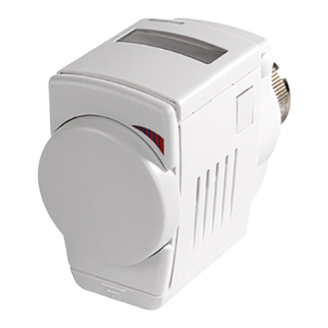
Honeywell
Honeywell HR 80 Installation and user guide


