I-G3N Z Series User manual

Z-RANGE LITHIUM BATTERY
REFERENCE MANUAL

1. Safety Precautions......................................................................................................................................................1
1.1. General warnings.........................................................................................................................................1
1.2. Charge and discharge warnings...................................................................................................................2
1.3. Transportation warnings................................................................................................................................2
1.4. Disposal of lithium batteries..........................................................................................................................2
1.5. Before Connecting........................................................................................................................................2
1.6. In Using.........................................................................................................................................................3
2. Introduction.................................................................................................................................................................4
2.1. Lithium iron phosphate battery ....................................................................................................................4
2.2. Z-Range Features.........................................................................................................................................5
2.3.Specications...............................................................................................................................................5
2.4. Equipment Interface Instruction....................................................................................................................6
2.5. Sleep and Wake up....................................................................................................................................11
2.5.1. Sleep...........................................................................................................................................11
2.5.2. Wake up......................................................................................................................................11
2.6. Forced discharge mode.............................................................................................................................11
2.7. Automatic parallel.......................................................................................................................................12
3. How to use the Z-Range ZRGP EmsTools...............................................................................................................13
3.1. Z-Range XRGP EmsTools connection........................................................................................................13
4. How to match communication with inverter .........................................................................................................17
4.1. Supported brands.......................................................................................................................................17
4.2. Inverter matching list..................................................................................................................................17
4.3. Connection with inverter..............................................................................................................................18
5. Safe handling of lithium batteries Guide.................................................................................................................19
5.1. Schematic Diagram of Solution..................................................................................................................19
5.2. Familiar with batteries.................................................................................................................................19
5.3. Precautions before installation....................................................................................................................19
5.4. Tools...........................................................................................................................................................20
5.5. Safety Gear.................................................................................................................................................20
6. Installation.................................................................................................................................................................21
6.1. Package Items............................................................................................................................................21
6.2. Installation Location....................................................................................................................................22
6.3. Parallel Installation......................................................................................................................................23
7. Trouble Shooting Steps............................................................................................................................................25
7.1. Problem determination based on...............................................................................................................25
7.2. Preliminary determination steps..................................................................................................................25
7.3. The battery cannot be charged or discharged...........................................................................................25
8. Storage,Transportationand Emergency Situations................................................................................................26
8.1. Storage.......................................................................................................................................................26
8.2. Transportation.............................................................................................................................................26
8.3. Emergency Situations..................................................................................................................................28
i
CONTENTS

SAFETY PRECAUTIONS
It is very important and necessary to read the user manual carefully (in the accessories)
before installing or using battery. Failure to do so or to follow any of the instructions or warnings
in this document can result in electrical shock, serious injury, or death, or can damage battery,
potentially rendering it inoperable.
1.1. General warnings
Observe these instructions and keep them located near the Li-ion Battery for future reference.
Work on a Li-ion Battery should be carried out by qualied personnel only.
• While working on the Li-ion Battery wear protective eyeglasses and clothing.
• Anyuncoveredbatterymaterialsuchaselectrolyteorpowderontheskinorintheeyesmustbeushedwith
plenty of clean water immediately. Then seek medical assistance. Spillages on clothing should be rinsed out with
water.
• Explosionandrehazard.TerminalsoftheLi-ionBatteryarealwaysalive;therefore,donotplaceitemsortools
on the Li-ion Battery. Avoid short circuits, too deep discharges, and too high charge currents. Use insulated
tools.Donotwearanymetallicitemssuchaswatches,bracelets,etc.Incaseofre,youmustuseatypeD,
foamorCO2reextinguisher.
• Do not open or dismantle the battery. Electrolyte is very corrosive. In normal working conditions contact with
the electrolyte is impossible. If the battery casing is damaged do not touch the exposed electrolyte or powder
because it is corrosive.
• Li-ion batteries are heavy. If involved in an accident they can become a projectile! Ensure adequate and secure
mounting and always use suitable handling equipment for transportation.
• Handle with care because a li-ion battery is sensitive to mechanical shock.
• Do not expose cable outside, all the battery terminals must be disconnected
• Do not place at a children or pet touchable area.
• Do not use cleaning solvents to clean battery.
• Donotexposebatterytoammableorharshchemicalsorvapors.
• Donotexposebatterytoammableorharshchemicalsorvapors.
• Donotexposebatterytoammableorharshchemicalsorvapors.
• Donotpaintanypartofbattery;includeanyinternalorexternalcomponents
• Donotpaintanypartofbattery;includeanyinternalorexternalcomponents
• Do not drop, deform, impact, cut or spearing with a sharp object.
• Do not wet the battery and avoid of direct sunlight.
• Do not use a damaged battery.
• Please contact the supplier within 24 hours if there is something abnormal.
• Any foreign object is prohibited to insert into any part of battery.
• The warranty claims are excluded for direct or indirect damage due to items above.
1SAFETY PRECAUTIONS

1.2. Charge and discharge warnings
Note
Batteries are tested according to UN Handbook of Tests and Criteria, part III, sub section 38.3
(ST/SG/AC.10/11/Rev.5).
• For transport the batteries belong to the category UN3480, Class 9, Packaging Group II and have to be transported according to this
regulation. This means that for land and sea transport (ADR, RID & IMDG) they have to be packed according to packaging instruction
P903 and for air transport (IATA) according to packaging instruction P965. The original packaging complies with these instructions.
1.4. Disposal of Lithium batteries
1.3. Transportation warnings
• If the battery is stored for long time, it is required to charge them every six months, and the SOC should be no
less than 90%.
• Battery needs to be recharged within 12 hours, after fully discharged.
• Do not connect battery with PV solar wiring directly.
• Use only with a Z-Range approved BMS
• If charged after the Lithium Battery was discharged below the “Discharge cut-off voltage”, or when the Lithium
Battery is damaged or overcharged, the Lithium Battery can release a harmful mixture of gasses such as
phosphate
• The temperature range over which the battery can be charged is 0°C to 55°C. Charging the battery at
temperatures outside this range may cause severe damage to the battery or reduce battery life expectancy.
• The temperature range over which the battery can be discharged is -15°C to 55°C. Discharging the battery at
temperatures outside this range may cause severe damage to the battery or reduce battery life expectancy.
• The battery must be transported in its original or equivalent package and in an upright position. If the battery is in
its package, use soft slings to avoid damage.
• Do not stand below a battery when it is hoisted.
• Never lift the battery at the terminals or the BMS communication cables, only lift the battery at the handles.
2
• Batteriesmarkedwiththerecyclingsymbolmustbeprocessedviaarecognizedrecyclingagency.By
agreement, they may be returned to the manufacturer.
• Batteries must not be mixed with domestic or industrial waste
• Donotthrowabatteryintore.
1.5. Before Connecting
• Afterunpacking,pleasecheckproductandpackinglistrst,ifproductisdamagedorlackofparts,please
contact with the local retailer.
• Before installation, be sure to cut off the grid power and make sure the battery is in the turned-off mode.
• Wiring must be correct, do not mistake the positive and negative cables, and ensure no short circuit with the
external device.
• It is prohibited to connect the battery and AC power directly.
• The embedded BMS in the battery is designed for 48VDC, please DO NOT connect battery in series.
• Battery system must be well grounded, and the resistance must be less than 1oumu.
• Make sure the grounding connection set correctly before operation.
• Please ensured the electrical parameters of battery system are compatible to related equipment.
• Keepthebatteryawayfromwaterandre
SAFETY PRECAUTIONS

1.6. In Using
• If the battery system needs to be moved or repaired, the power must be cut off and the battery is
completely shut down.
• It is prohibited to connect the battery with different type of battery.
• It is prohibited to put the batteries working with faulty or incompatible inverter.
• It is prohibited to disassemble the battery (QC tab removed or damaged).
• Incaseofre,onlydrypowderreextinguishercanbeused,liquidreextinguishersareprohibited.
• Pleasedonotopen,repair,ordisassemblethebatteryexceptstaffsfromi-G3Norauthorizedby
i-G3N. We do not undertake any consequences or related responsibility which because of violation of
safety operation or violating of design, production, and equipment safety standards.
3SAFETY PRECAUTIONS

2. INTRODUCTION
Z-Range lithium iron phosphate battery is one of new energy storage products developed and
produced by i-G3N, it can be used to support reliable power for various types of equipment’s and
systems. Z-Range is especially suitable for application scene of high power, limited installation
space, and restricted load-bearing and long cycle life.
Z-Range has built-in BMS battery management system, which can manage and monitor cells
information including voltage, current and temperature. What is more, BMS can help extending
cycle life by balancing cells during charging and discharging.
Multiple batteries can be connected in parallel to expand capacity and power to meet the
requirements of longer power supporting duration and higher power consumption.
2.1. Lithium iron phosphate battery
The lithium iron phosphate battery (LiFePO4 or LFP) is the safest of the mainstream lithium battery
types. A single LFP cell has a nominal voltage of 3.2V. A 51.2V LFP battery consists of 16 cells
connected in series.
LFP is the chemistry of choice for very demanding applications. Some of its features are:
• Rugged-Itcanoperateindecitmodeduringlongperiodsoftime.
• Highroundtripefciency.
• High energy density - More capacity with less weight and volume.
• High charge and discharge currents - Fast charge and discharges are possible
• Flexible charge voltages.
The lithium iron phosphate battery is therefore the chemistry of choice for a range of very
demanding applications.
4INTRODUCTION

2.2. Z-Range Features
• The whole module is non-toxic, non-polluting, and environmentally friendly.
• Cathode material is made from LiFePO4 with safety performance and long cycle life.
• Battery management system (BMS) has protection functions including over-discharge, over-
charge, and over-current and high/low temperature.
• The system can automatically manage charge and discharge state and balance current and
voltage of each cell.
• Flexibleconguration,multiplebatterymodulescanbeinparallelforexpandingcapacityand
power, up to 63 batteries in parallel.
• Adopted self-cooling mode rapidly reduced system entire noise.
• The module has less self-discharge, up to 6 months without charging it on shelf, no
memoryeffect, excellent performance of shallow charge and discharge.
• Workingtemperaturerangeisfrom-15to55°C,(Charging0~55°C;discharging-15~55°C)
withexcellentdischargeperformanceandcyclelife;
• Smallsizeandlightweight,standardof19-inchembeddeddesignedmoduleiseasyfor
installation and maintenance.
2.3. Specications
Figure 2.1. Outline dimensional drawing
INTRODUCTION 5

No Item ZR-FC4850 ZR-FC48100 ZR-FC24200
1 Battery Model 50Ah/3.2V 100Ah/3.2V 200Ah/3.2V
2 Compound Mode 1P16S 1P15S 1P16S 1P15S 1P8S
3 Rated Capacity 50Ah 100Ah 200Ah
4 Rated Energy 2560Wh 2400Wh 5120Wh 4800Wh 5120W
5 Initial Resistance <50mΩ
6 Nominal Voltage 51.2V 48V 51.2V 48V 25.6V
7 Charge Cut-off Voltage 57V 53V 57V 53V 28.5V
8 Discharge Cut-off Voltage 47V 44V 47V 44V 23.5V
9 Rated Charging Current 10A 20A 20A
10 Maximum Charging Current 50Ah ≤100A ≤100A
11 Rated Discharge Current 25A 50A 50A
12 Maximum Discharge Current ≤50A ≤100A ≤100A
13 Charging Temperature -0~+55°C
Discharge Temperature -15~+55°C
14 Open-circuit voltage 44~57V 23.5~28.5
15 Shell Type Painted metal
16 Weight 33±1Kg 31.7±1Kg 45±1Kg 43±1Kg 45±1Kg
17 Size 408(L)*440(W)*132(H)mm
2.4. Equipment Interface Instruction
Figure 2.2. Interface denition
No Instructions No. Instructions
1 Battery Cathode (same as port 2) 9 Address Dial Switch
2 Batttery cathode (same as port 1) 10 RS232 communication port
3 Power Switch 11 Multi-Device parellel connection 1
4 GND 12 Multi-Device Parrellel connection 2
5 SOC indicator 13 Reset Button
6 Alarm Indicator 14 CAN/RS485 communication port
7 Run indicator 15 Battery anode (same as the port 16)
8 dry contact 16 Battery anode (same as the port 15)
INTRODUCTION 6

Power Switch
• Power switch: to turn ON/OFF the whole battery. When it is off, BMS standby, no power output.
Dry contact
• Dry contact: provided 2 ways output dry contact signal.
Address dial switch
• ADD Switch: 6 ADD switches, “0”and “1”, refer to picture right. The settings will be active only
after restart the battery.
• When the battery communicates with the inverter, the address of the battery pack must be set
to 1, and the address of the parallel slave should be greater than 1.
• When the battery Pack is connected in parallel, cascading communication is required.
HardwareaddresscongurationisrequiredforboththemasterPACKandtheslavePACK,
andthehardwareaddresscanbesetbythedialswitchontheboard.Thedenitionofthe
switch refers to the table below.
Address Dial Switch Position Instruction
#1 #2 #3 #4 #5 #6
1 On Off Off Off Off Off use lonely main
2 Off On Off Off Off Off Set as Pack 1
3 On On Off Off Off Off Set as Pack 2
4 Off Off On Off Off Off Set as Pack 3
5 On Off On Off Off Off Set as Pack 4
6 Off On On Off Off Off Set as Pack 5
7 On On On Off Off Off Set as pack 6
8 Off Off Off On Off Off Set as Pack 7
9 On Off Off On Off Off Set as Pack 8
10 Off On Off On Off Off Set as Pack 9
11 Off Off On On Off Off Set as Pack10
12 Off Off On On Off Off Set as Pack 11
13 On Off On On Off Off Set as Pack 12
14 Off On On On Off Off Set as Pack 13
15 On On On On Off Off Set as Pack 14
16 Off Off Off Off On Off Set as Pack 15
.... ... .... .... .... .... .... ....
62 Off On On On On On
63 On On On On On On
INTRODUCTION 7

RS232 communication port
• RS232 communication port: (RJ11 port) comply with RS232 protocol (baud rate: 9600), for
manufacturers or professional engineers debugging or service.
Port denitions RJ11 Pin Function
1 NC
2 RS232-GND
3 RS232-TX
4 RS232-RX
5 RS232-GND
6 NC
Multi-device parallel connection 1 and Multi-device parallel connection 2
• Multi-device parallel connection: The same RJ45 port, two RJ45 parallel. Comply with RS485
protocol (baud rate: 9600), used for parallel communication between batteries.
Port denitions RJ45 Pin Function
1 RS485-B
2 RS485-A
3 RS485-GND
4 NC (No connect)
5 NC (No connect)
6 RS485-GND
7 RS485-A
8 RS485-B
Reset Button
• When Battery is in sleep mode, press the key for 3S and release it, the Battery will be
activated, and the LED indicators will light up from left to right, and then showing the SOC of
the battery.
• When Battery is in the active state, press the key for 3S and release it, the Battery will go into
sleep mode, and the LED indicators will light up from right to left and then all the indicators
will be off.
• When Battery is in the active state, press the button for 6S and then release, the battery
parameters are restored to factory settings, and all LED lights are on for 1.5 seconds.
NOTE
• If there are other batteries in the output state in parallel application scenario, the current battery cannot be set to sleep through the reset
button at this time, because it will be charged and awakened by other batteries with normal output.
INTRODUCTION 8

CAN/RS485 communication port
• CAN/RS485 communication port: (RJ45 port) follow CAN protocol and RS485 protocol, for
output batteries information, the battery uses this interface to communicate with external
inverters, PCS, and other devices.
Port denitions RJ45 Pin Function
1 RS485-B
2 RS485-A
3 NC (No connect)
4 NC (No connect)
5 RS485-GND\CAN-GND
6 NC (No connect)
7 CANH
8 CANL
Battery anode and Battery cathode
• Battery anode and Battery cathode: there are two pair of terminals with same function,
one connects to equipment, the other one paralleling to other battery module for capacity
expanding. For each single module, each terminal can achieve charging and discharging
function. For power cables uses water-proofed connectors. It must keep pressing this Lock
Button while pulling out the power plug.
SOC indicator, Alarm indicator and Run indicator
• SOC indicator: 4 green LEDs to show the battery’s current capacity.
• Alarmindicator:redLEDashingtoshowthebatteryhasalarm,andalways-ontoshowthe
battery is under protection.
• Runindicator:greenLEDalways-ontoshowthebatteryrunningstatus,ashingwhen
charging, and lighting when discharging.
INTRODUCTION 9

Table 1 LED working state indication
Status Normal/ Warning/
Protection
Run ALM LED Capacity
Indicator
Instruction
Power Off Sleep Off Off Off Off Off Off All Off
Standby Normal Flash 1 Off According to
Capacity
Standby
Warning Flash 1 Flash 3 Low Voltage
Charging Normal On Off According to
Capacity Indicator
(Capacity Indicate
Max.LEDash2
times)
Overcharge alarm ALM
not Flicker
Warning On Flash 3
Overcharge
Protection
On Off On On On On Indicator Staus without
AC input
Tempreture
Overcurrent and
Failure Protection
Off On Off Off Off Off Stop Charging
Discharging Normal Flash 3 Off According to
Capacity Indication
Warning Flash 3 Flash 3
Under voltage
protection
Off Off Off Off Off Off Stop Discharging
tempreture,
Overcurrent, Short
Circuit, reverse
Connection, Failure
protection
Off On Off Off Off Off Stop Discharging
Failure Failure Off On Off Off Off Off Stop Charge and
Discharge
Parallel Address >1 and not
connected
Flash 3 \ \ \ \ \ The slave waits for
parallel state
*SeedenitionforFlash1/2/3inthefollowingpage.
Table 2 Capacity Indication
Status Charge Discharge
Capacity Indicators L4 L3 L2 L1 L4 L3 L2 L1
Capacity (%) 0~25% Off Off Off Blink 2 Off Off Off On
25~50% Off Off Blink 2 On Off Off On On
50~75% Off Blink 2 On On Off On On On
75~100% Blink 2 On On On On On On On
Running Indicators On Blink 3
Table3LEDashinginstructions
Blink On Off
Blink 1 0.25s 3.75s
Blink 2 0.5s 0.5s
Blink 3 0.5s 1.5s
INTRODUCTION 10

2.5. Sleep and Wake up
2.5.1. Sleep
When any of the following conditions is met, the battery enters the low-power mode:
1. Under voltage protection is not released within 30 seconds.
2. Press the reset button for 3 seconds and then release the button.
3. The lowest cell voltage is lower than the sleep voltage, and the duration reaches the
sleep delay time (while meeting the requirements of no communication, no protection, no
equilibrium, and no current).
4. Standby mode lasts for more than 24 hours (no communication, no charge and discharge, no
mains power, minimum cell is less than 3.2V).
5. Forced shutdown from the Z-Range ZRGP EmsTools.
Before entering sleep, make sure no charger is connected, otherwise it will not be able to enter
low-power mode.
2.5.2. Wake up
Whenthesystemisinthelow-powermodeandanyofthefollowingconditionsissatised,the
system will exit the low-power mode and enter the normal operation mode:
1. Connect the charger, and the output voltage of the charger must be greater than 48V.
2. Press the reset button for 3 seconds and release the button.
3. Connect the communication line and open the Z-Range ZRGP EmsTools (if enters sleep mode
due to over-release protection, and this method cannot wake up the battery).
4. Use the power software switch.
Note
• After battery over-discharge protection, it enters the low-power mode, wakes up at a regular time every 4 hours, and starts open switch to
charging or discharging. If it can be charged, it will exit the sleep mode and enter the normal charging state. If the auto wakes up fails to
charge for 10 consecutive times, it will no longer auto wake up. When the system is dened as the end of charging, and the recovery voltage
is still not reached after 2 days /48h standby time (standby time set value), it is forced to resume charging until the end of recharging.
2.6. Forced discharge mode
When the battery is in the sleep mode by undervoltage protect and the lowest cell is greater than
2.0V,rstclosethepowerswitch,andthenwaitfor2Sbeforeturningonthepowerswitch,and
the battery enters the forced discharge mode for 5 minutes. In the forced discharge mode, if
there is a charge, the battery will exit the forced discharge mode and switch to the normal mode.
If the discharge current exceeds 20A or there is no charge current within 5 minutes, the battery
will re-enter the sleep mode.
INTRODUCTION 11

2.7. Automatic parallel
With automatic parallel function, when the slave battery (address > 1) is powered on, the charge
and discharge switch is in disconnect state. When the voltage difference between the slave
battery and master battery is less than the condition of “the minimum voltage difference between
the slave and the master”, the master sends the command to the slave. After the slave receives
the command from the master, the charge and discharge switch will be connected, and the slave
is integrated into the master system to complete the parallel operation.
INTRODUCTION 12
HOW TO USE THE Z-RANGE ZRGP EMS TOOLS
3.1. Z-Range ZRGP EmsTools connection
• Connect the RS232 interface of the battery to the computer using the RS232 communication
line (this accessory is an optional accessory, need to be purchased separately from the
manufacturer).
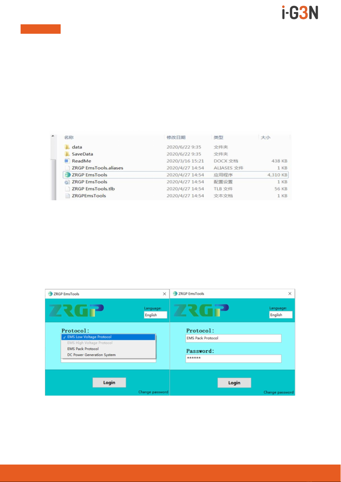
• UnzipthepackageleoftheZ-RangeZRGPEmsToolsinthesameledirectory,pay
attentiontothedirectorydonotstoreotherles.
Figure 3.1. Unzip of Z-Range ZRGP EmsTools
• Open the Z-Range ZRGP Emstools icon,enter the Protocols election interface,select the EMS
Pack Protocol version, and enter the password (please contact the manufacturer for the
password) to log in the software.
Figure 3.2. Protocol selection interface Figure 3.3. Enter the password
HOW TO USE THE ZRGP EMS TOOLS 13

• Users can set different languages according to their own needs.We support our languages,
whichareSimpliedChinese,English,JapaneseandSpanish.
Figure 3.4. ZRGP Emstools language selection
• Select the serial port number in the EMS low-voltage version of theZ-Range ZRGP Ems tools,
and the baud rate is 9600 by default. Click “Open COM” and “Monitor ON” button.
Figure 3.5. Z-Range ZRGP Emstools serial port settings
Figure 3.6. Z-Range ZRGP Emstools data acquisition
HOW TO USE THE ZRGP EMS TOOLS 14

• The corresponding functions can be selected through the navigation bar oftheZ-RangeZRGP
EMS Pack.
Historical data recording
• ZRGP Emstools supports real-time data recording function, which can record the parameters
and state information of the battery when it is running.
• By clicking the Historical data menu to switch, all the historical data which collected by
Z-Range ZRGP
• Emstools can be read at any time, those historical also can be export to computer and save
intoExcelformatles.
Figure 3.7. Z-Range ZRGP Emstools historical data recording
Log Recording
• The BMS inside the battery pack uses FLASH chip to record the battery operation data, these
data mainly include some parameters such as alarm, protection, fault, state switch, etc., and
after-salespersonnelcanevaluateandanalyzetherunningstateoftheproductaccordingto
this log information, battery can support log recording for more than 10 years at most.
Figure 3.8. Z-Range ZRGP Emstools Log recording
HOW TO USE THE ZRGP EMS TOOLS 15
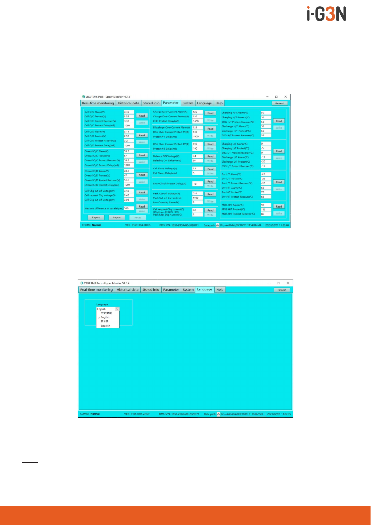
Parameter Setting
• Z-RangeZRGPEMSPacksupportsthesettingandmodicationofbatteryalarm,protection
and other parameters. The user needs to enter the password in the lower right corner of the
Real-time Monitoring page (the password needs to be obtained from the manufacturer) to
modify and set these parameters, refer to Figures 3.6 and Figures 3.9.
Figure 3.9. Z-Range ZRGP Emstools Parameters Setting
Language Setting
• In addition to setting the language on the login interface, users can also set it in the
“language” option card in the navigation bar, as shown below:
Figure 3.10. Z-Range ZRGP Emstools Language Setting
HOW TO USE THE ZRGP EMS TOOLS 16
Help
• TheusercanlearnabouttheZ-RangeZRGPEMSPacksoftwareandopenthehelpleatthe
“Help” option card in the navigation bar.

HOW TO MATCH COMMUNICATION WITH INVERTER
4.1. Supported brands
At present, the energy storage products of our company have completed matching tests with
some series inverters of the following brands, and we will continue matching tests with inverters
of other companies.
4.2. Inverter matching list
The list tab only lists the inverter manufacturers one of the same series products, general inverter
manufacturers in the same series of other products, the communication protocol are the same, so
our battery can be communicated with the other products of same series inverter, if encounter a
series of products can’t communication, please contact us.
The following inverter matching list may not be up to date. The list may change according to
the software version upgrade, and the reference manual may does not change immediately
according to the software version upgrade.
The inverter manufacturer may upgrade its software version, which may cause problems in the
communication between our battery and the inverter. Therefore, before communicating with the
inverter,pleaseconrmwhetherthesoftwareversionoftheinverterisconsistentwiththelist.If
not, please contact us.
Inverter ZR-FC Firmware
version
Communication
mode
Brand Type Protocol Version
Growatt SPF SPF 12KT HVM 1.22 V446 RS485
Growatt SPA/SPH SPA/SPHT 1.3 CAN
Studer Xtender-
XTH-8000-48
V1.0.3 Xcom-CAN
Sofar HYD5000-ES V6.0 CAN
Solis RHI-5K-48ES V1.2 CAN
Goodwe GW5048-EM V1.5 CAN
Victron MultiPlus-II V6.0 CAN
SMA S16.0H-12 V2.0 CAN
Sermatec SMT-5K-TL-UN V1.2 CAN
Schneider ContextTM Gateway V2.0 RS485
SUN SYNK(Deye) SUNSYNK-5K-
SG01LP1
V1.2 CAN
SOL ARK SOL-ARK-12K V1.0 CAN
Li_PLUS ZRStandard V1.2 CAN
HOW TO MATCH COMMUNICATION WITH INVERTER 17

4.3. Connection with inverter
This section will introduce how to hardware connect Z-Range products with 8.2 section “Inverter
Matching List”. Inverters manufacturers may upgrade their products, resulting in hardware
communication interface changes. If communication is not possible in the application according
to the following wiring method, please contact with us.
The CAN/RS485 communication port of Z-Range relates to the communication interface of
inverter.
Connect to the Vitron Inverter Connect to the SUN SYNK inverter
Connect to the Growatt SPF Inverter Connect to the Sofar inverter
Connect to the Solis inverter Connect to the Goodewe inverter
Connect to the Sermateci inverter Connect to the Growatt-SPA/ SPH inverter
Note
• The above CAN and RS485 communication connections are not connected the ground wire, in the application of relatively large interference,
it is recommended to connect the ground wire, the ground wire connection method is a single-ended shielding line.
HOW TO MATCH COMMUNICATION WITH INVERTER 18
This manual suits for next models
3
Table of contents
Other I-G3N Camera Accessories manuals


