I-GO DISCOVERY ROSEMONT LE1 User manual

ELECTRIC BIKES
OWNER MANUAL
DISCOVERY ROSEMONT LE1
DISCOVERY YORKVILLE LE1
DISCOVERY ROSEMOUNT LS1
DISCOVERY YORKVILLE LS1
OUTLAND CABOT RS1
OUTLAND SAWBACK RS1
OUTLAND TORNGAT RS1
RIDE
THIS WAY

2 3
CONGRATULATIONS
YOU ARE THE PROUD NEW OWNER OF AN iGO eBIKE
We have taken great care to create an incredible product and hope you enjoy riding it as much
as we enjoyed creating it. We encourage you to take the time to familiarize yourself with all the
functions and capabilities that are now available to you - please read this comprehensive guide
carefully before riding your new eBike. Whether you ride to commute, to go shopping or just
ride for riding’s sake, you will do so in comfort and condence on your new iGO electric bike.
If you want to know more about your electric bike or discover tips and hints to get the
most out of any ride, consult the ever expanding wealth of knowledge available at :
assist.igoelectric.com
We wish you many happy rides with your new electric bike.
FRAME SERIAL NUMBER
The serial number is located on the frame on a label on the underside of the
down tube or non-drive side chainstay (close to the bottom bracket)
My serial number is :
--------------
My key number is : ----
Your electric bike may differ from the illustrations in this manual.
iGO highly recommends having your new eBike assembled and
adjusted by a professional bicycle technician.
Note:
iGO Electric reserves the right to make changes without notice
to design(s) and / prices listed in this manual.
This manual has been compiled with great care. iGO cannot
be held responsible for any inaccuracies.
IDENTIFY YOUR iGO ELECTRIC BIKE
I am the proud owner of :
REGISTER YOUR eBIKE
To gain full access to all owners benets and warranty coverage register your bike at :
register.igoelectric.com
I shall affectionately refer to my bike as :
I bought this from :
(date) :
(key number can be found on a metal tag attached with the keyring)
serial number
DISCOVERY ROSEMONT LE1 DISCOVERY YORKVILLE LE1 DISCOVERY ROSEMONT LS1
DISCOVERY YORKVILLE LS1 OUTLAND CABOT RS1 OUTLAND SAWBACK RS1
OUTLAND TORNGAT RS1

4 5
TABLE OF CONTENTS
iGO DRIVE
About iGO Drive
Display And Functions
Operating The Display Unit
Display Settings
Advanced Settings
What Is Pedal Assistance?
About Cadence Sensing
About Torque Sensing
About Walk Assist
Throttle
Removing The Throttle
Battery
Identify The Battery
Remove / Install Battery
Charging The Battery
Battery Range And Capacity
Important Battery Safety Information
Electronics Access Port (EAP)
Weatherproof Connectors
MECHANICAL COMPONENTS
The Groupset
About Gears And Shifting
Shimano Trigger Shifters
How To Bed In New Disc Brake Pads
Disc Brake Alignment
Adjusting Hydraulic Disc Brakes
Adjustability And iGO Ergot
Adjusting The Seat Height
Adjusting The Saddle Position
Adjusting The Handlebars (Quick Release)
Installing The Handlebars (4 Bolt Stem)
Rear Wheel Removal And Installation
Tire Pressure
Adjusting The Suspension Fork
Quick Release, Q-Loc, And Thru Axel Fork
iGO ASSIST
What Is iGO Assist?
How To Access iGO Assist
Diagnostics And Warning Codes
Main Technical Parameters, Specications, And Parts :
Discovery Rosemont LE1
Discovery Yorkville LE1
Discovery Rosemont LS1
Discovery Yorkville LS1
Outland Cabot RS1
Outland Sawback RS1
Outland Torngat RS1
Torque Table
Servicing
Cleaning
Important Safety Instructions
WARRANTY
Warranty Limitations
Warranty Terms
REGISTER YOUR eBIKE
6
6
7
7
9
10
12
12
12
13
13
14
14
15
16
17
18
19
20
20
21
21
21
22
22
23
23
24
24
24
25
25
26
26
27
27
30
30
30
31
32
33
34
35
36
37
38
39
40
40
41
43
43
44
47
For assistance setting up your new iGO eBike, a full
assembly instruction video is available at :
www.igoelectric.com/unboxing
6 7
iGO DRIVE
ABOUT iGO DRIVE
Each iGO Drive system has been developed and custom congured for optimal
performance within the dened parameters of each eBike. The systems are :
LE DRIVE : Smooth, simple, dependable for consistent and effortless control. 32 pulse
electronic cadence sensor. Geared rear hub motor. 500W | 48V | up to 55Nm torque.
Drive system custom congured for leisure focused riding.
LS DRIVE : Intuitive natural ride experience for energetic active transport.
Dynamic mid motor system with torque, cadence, and speed sensor. 350W |
48V | up to 100Nm torque. Drive system features city tuned conguration.
RS DRIVE : Powerful, exciting, and sport performance delivering a natural ride experience on
or off road. High output dynamic mid motor system with torque, cadence, and speed sensor.
500W | 48V | up to 130Nm torque.
Drive systems are custom congured for each application
(all-road tuned/cross-country tuned).
Each utilizes an advanced electric system to offer efciency in performance, system
information, and safety when in use or during storage. Connection to the peripheral
components is by quick secure weatherproof connectors, allowing for simple maintenance
and customization. The primary control unit and cyclocomputer interface is attached to the
eBike handlebar for quick access to settings, system information, and diagnostic tools.
MULTI CLASS SWITCHABLE
These iGO Drive systems are programmed to be ‘multi class switchable’ allowing parameters
to be instantly recongured at the touch of a button to conform to Class 1, 2, or 3 regulations.
Throttle thumb controls on iGO eBikes function when in Class 2 and 3, and are fully
disabled in Class 1. The throttle can easily be removed from the eBike when not required.
DISPLAY AND FUNCTIONS
The battery must be installed in the electric bike for the display to function.
Make sure that the battery is securely locked into the bike prior to riding.
It is recommended to remove and securely store the key when you are riding your electric bike.
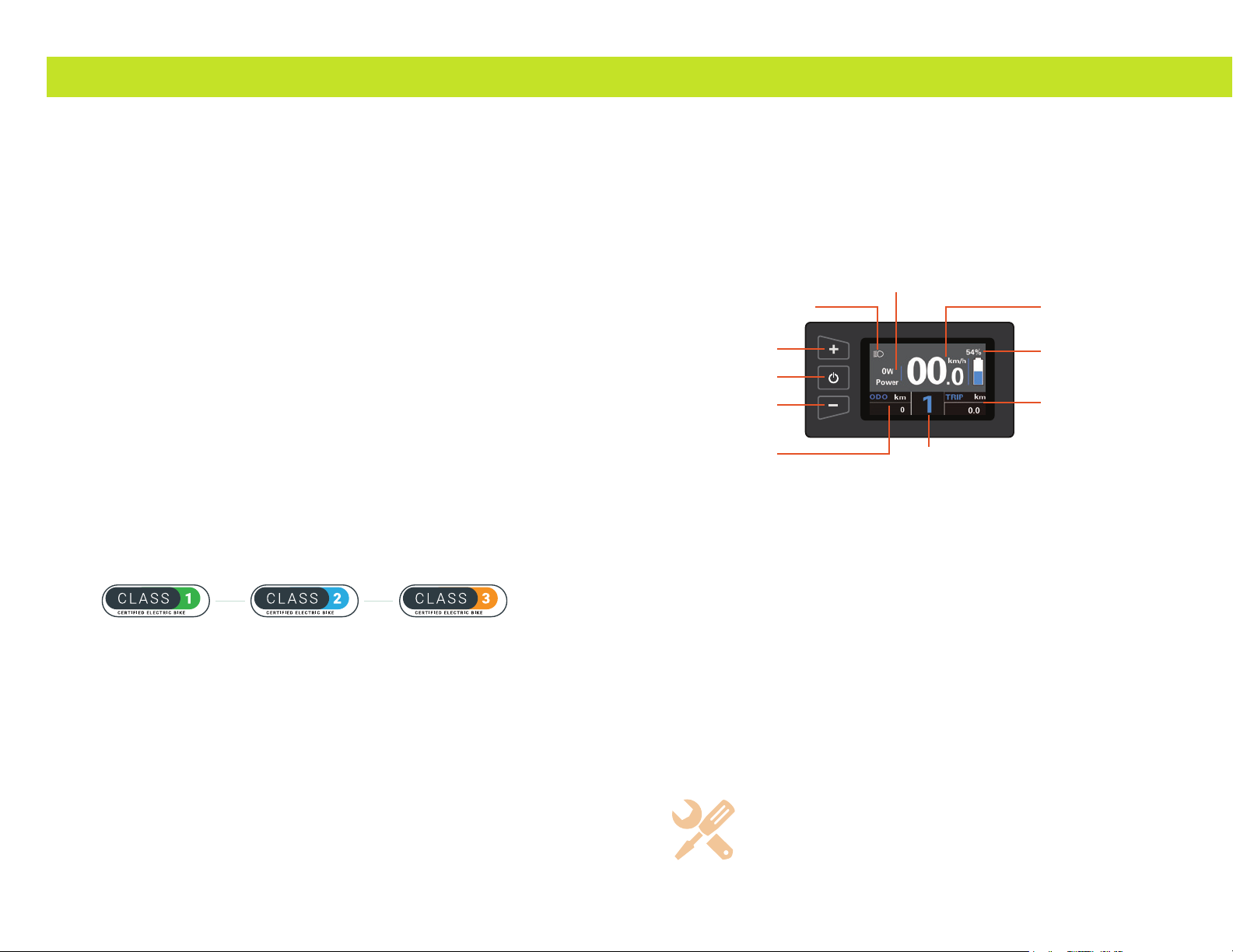
The display unit houses controls for the electric systems of the
iGO eBikes and is also the cyclocomputer interface.
OPERATING THE DISPLAY UNIT
Power on/off
Turn the power on or off by pressing and holding the POWER button
for 3 seconds. The power will automatically turn off after the bike is
inactive for approximately 10 minutes to conserve energy.
Change PAS level
Short press the PLUS (+) or MINUS (-) button to switch between PAS levels. When
power is turned on, your iGO eBike will start in PAS ‘0’ as a safety precaution.
In this state no power is provided to the throttle or to the pedal assist.
Lights and display backlight on/off
To turn the display backlight (and any installed headlight/rear light)
on or off press & hold the PLUS (+) button for 2 seconds.
Walk assist
Press & hold the MINUS (-) button to engage walk assist.
Release the MINUS (-) button to disengage walk assist.
Note : If a diagnostic (warning/error) icon and code appears on the eBike’s
display unit, check the table on page 31 and take the appropriate action.
SPEEDOMETER
BATTERY CHARGE
TRIP ODOMETER
LIGHT ON/OFF
MOTOR POWER
MODE
option & value PAS LEVEL
and walk mode indication
PLUS (+)
MINUS (-)
POWER BUTTON
8 9
iGO DRIVE
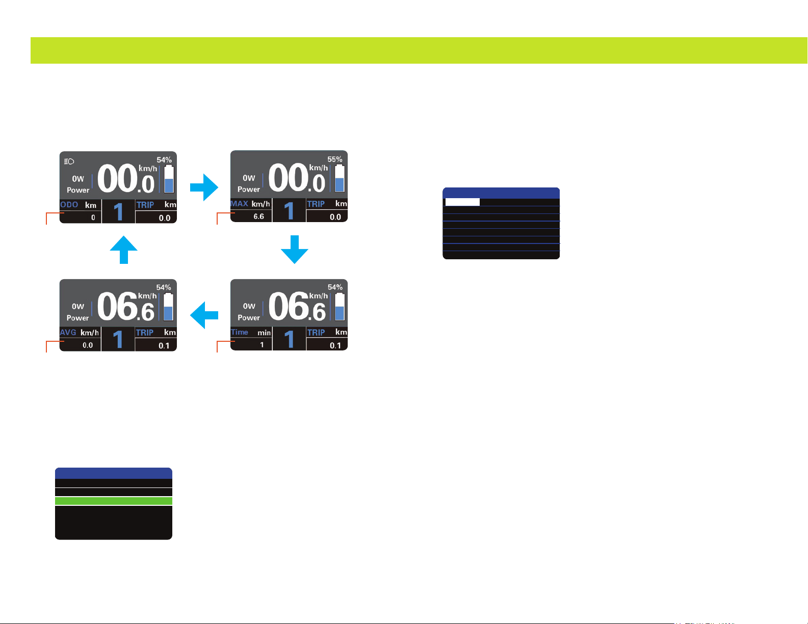
Display mode
After switching on the eBike, the bottom left segment on the display will show the Odometer.
Short press the POWER BUTTON to toggle through the following display modes :
odometer | maximum speed | average speed | trip time
Settings menus
With the display on, press and hold the PLUS (+) and MINUS (-)
buttons simultaneously to access the settings menus.
use the PLUS (+) or MINUS (-) buttons to toggle through the listed options.
Short press the POWER BUTTON to select the hi-lighted option.
Note :
Settings can only be changed when the eBike is safely parked and not moving.
DISPLAY SETTINGS
use the PLUS (+) or MINUS (-) buttons to toggle through the list options.
Short press the POWER BUTTON to select the hi-lighted option.
use the PLUS (+) or MINUS (-) buttons to toggle through the selected option’s values.
Short press the POWER BUTTON to conrm and save the hi-lighted value.
Trip Reset
YES : Clear the trip odometer (single ride) distance value.
NO : cancel the trip reset and return to the option list.
Toggle Unit
Metric : set distance and speed to display in kilometers (km/h).
Imperial : set distance and speed to display in miles (MPH).
Wheel
Set the wheel diameter value. The default value should be the correct value
for your bike. Changing to a different value that does not match actual wheel
diameter may cause distance and speed values to display incorrectly.
Speed Limit
Changing from the default may only affect the speed indicated
on the display. This will NOT affect the assist speed.
Set Voltage
Set displayed battery voltage values. The default value should be the correct value
for your bike. If you are unsure the value set is correct contact iGO support.
1 : 31.6
2 : 34.6
3 : 35.6
4 : 37.4
5 : 39.2
SOC View (battery State of Charge)
01 : Display battery State of Charge as a percentage (%)
02 : Display battery State of Charge as voltage (V).
Back
Return to the previous menu.
ODOMETER MAX. SPEED
AVERAGE SPEED TRIP TIME
SETTING
Display Settings
Advanced Settings
EXIT
Display Setting
Wheel
Speed Limit
Set Voltage
SOC View
BACK
TRIP Reset
Toggle Unit
27.5 inch
17Km/h
36V
Percent
NO
Metric

10 11
iGO DRIVE
ADVANCED SETTINGS
use the PLUS (+) or MINUS (-) buttons to toggle through the list options.
Short press the POWER BUTTON to select the hi-lighted option.
use the PLUS (+) or MINUS (-) buttons to toggle through the selected option’s values.
Short press the POWER BUTTON to conrm and save the hi-lighted value.
Power Set
Change the number of PAS levels used. 0-5 is the default value.
Selecting less levels of assist will deliver greater difference between each PAS level. Selecting
more assist levels will deliver a more gradual step up and down between each PAS levels.
Select from these values :
0-3 |1-3 |0-5 |1-5 |0-7 |1-7 |0-9 |1-9
Note : If a value is selected that does not include ‘0’ the eBike will start up in PAS ‘1’
i.e. touching the throttle at any time will cause the bike to move.
Take caution when using these values.
Current Limit
Value assigned to the controller ‘over-current’ cut setting. The default
value is 22A and should be the correct value for your bike. If you believe the
value or function is not working as expected contact iGO support.
LCD Luminance
Change the backlight brightness of the display unit (%).
Cruise Enable
ON or OFF.
Mode
iGO eBikes listed in this manual are MULTI CLASS SWITCHABLE through the display unit.
Select from the ‘mode’ values to reset the bike parameters and the eBike
will instantly conform to Class 1, Class 2, or Class 3 regulations.
Class_1 : No throttle function, PAS with maximum speed 32km/h (20mph)
Class_2 : Throttle and PAS maximum speed 32km/h (20mph)
Class_3 : Throttle maximum speed 32km/h (20mph), PAS maximum speed 45km/h (28mph)
To engage class 3 the rider can only operate where permitted by local regulations
and accept the liabilities and responsibilities of riding in this class.
ATTENTION : Riding an ebike in class 3 in an area prohibited by law is a punishable offence. It
is the riders responsibility to familiarize themselves regarding these regulations and further
agrees to hold iGO/Fermetco harmless or responsible in any way in the operation of their ebike.
Password
Select the ‘>’ option to enter the password menu.
Select ‘Start Password’ and Short press the POWER BUTTON to proceed with
setting a password that will protect the electric functions of the eBike.
A prompt will appear to enter a 4 digit password. Use the PLUS (+)
or MINUS (-) buttons to toggle through numbers and Short press the
POWER BUTTON to conrm and proceed to the next number.
Once all four numbers have been entered a prompt will appear to conrm the
password. Re-enter the 4 digit password to proceed. If the passwords do not
match an alert will be shown and the conrmation will need to be reentered.
A conrmation screen will show to indicate the password requirement has been set.
When active, the password can be reset (change the password) or set to OFF. Each of
these options will require entering the current password before being able to proceed.
Note : the display will be powered off automatically if an incorrect password is entered ten
times.
When active, the 4 digit code will be required every time the display unit is powered on,
before the eBike electrical system can become operational. A password prompt will show
at start up and allows up to three attempts to input the correct numbers. The correct code
must be entered to access the electrical system controls and cyclocomputer interface.
PLEASE TAKE CARE TO REMEMBER YOUR PASSWORD AND ENSURE THE PASSWORD IS KEPT SAFE.
Back
Return to the previous menu.
Advanced Settings
LCD Luminance
Cruise Enable
MODE
Password
BACK
Power Set
Current Limit
100%
ON
CLASS_3
>
0-9
22A
Password Set
BACK
Start Password OFF
Password Set
BACK
Start Password
Reset Password
ON
Password Set
Please Input Your
Password
----
12 13
WHAT IS PEDAL ASSISTANCE?
Pedal assistance is the way an electric bicycle enhances - or magnies - the effort exerted by
the rider on each pedal stroke. This will allow the rider to travel further or faster while exerting
the same effort, or simply enjoy a more relaxed ride while using less energy and effort.
The amount of assistance provided by the motor (how much a riders effort is magnied) is
indicated by the Pedal Assist System (PAS) level. These iGO eBikes have a 5 level PAS. As a rule,
a lower PAS number will indicate the motor is providing less assistance (ideal for at roads,
paths, light assistance) and a higher PAS number will indicate an increased assistance from the
motor (for when you are riding up a steep incline, into a strong headwind, carrying a heavy load,
or just want a more relaxing ride).
If the assistance is set to ‘0’ all assistance will be disengage when pedaling, allowing the bike
to be ridden as a standard non electric bicycle. The lights and cyclocomputer functions will
continue to function but the motion of the bicycle will rely solely on the riders manual effort.
(For your safety iGO electric bicycles default to PAS level 0 each time the bike is powered on
for safe mounting and dismounting.)
Note : the throttle will also be inactive when assistance is set to ‘0’.
Be aware that the motor will draw more power from the battery as more assistance
is used. Extending the range of the battery can be achieved by reducing the intensity
of assist used. Understanding the efcient use of bikes gears to complement
pedal assist levels will allow for a smoother riding experience, can extend the
range of the battery and has an added benet of exerting less stress on bike
components allowing them to last longer before requiring replacement.
Assistance will engage in different ways depending on the type of sensor being used.
ABOUT CADENCE SENSING
Pedal assist with cadence sensor allows the rider to have assistance as soon as the rider
begins to pedal and for as long as the rider continues to pedal. The iGO cadence sensor is
located in the bottom bracket, weather-proof and away from potential harm or tampering. It
uses up to 32 optic sensor points to let the system know when the rider has started or stopped
pedaling making it extremely efcient and uid in the system’s ability to deliver assistance.
ABOUT TORQUE SENSING
Pedal assist with a torque sensor enables the system to provide measured
assistance based on the rider’s effort. The sensor uses pressure and strain gauges
to measure the effort that the rider is putting into the pedals and provides
the required assistance to ensure a smooth and comfortable balance. The
more effort the rider puts into the pedals, the more the system assists.
ABOUT WALK ASSIST
USE CAUTION WHEN ENGAGING THIS FEATURE AND ENSURE THAT YOU ARE
IN CONTROL OF THE BICYCLE BEFORE OPERATING WALK MODE
Walk Assist mode enables the bike to “walk” beside the rider at 6km/h. This feature is practical
for walking the bike up-hill, when guiding on to a bike rack or carrier as well as when advancing
with the bike over any surface that may be difcult to pull/push the bike through (mud, snow,
sand, etc).
Release the MINUS (-) button to disengage walk assist at any time. As a further safety measure
pulling on either brake lever will trigger the power-cut off switch which will disengage power
and walk assist.
THROTTLE
Throttle thumb controls on iGO eBikes function when in Class 2 and 3, and are fully
disabled in Class 1. Pushing down on the throttle will provide an immediate boost
of acceleration to the bike (whether pedaling or not). The bicycle will continue to
accelerate until the throttle is released or when the bicycle reaches its maximum
assist speed limit. If the throttle is held down while at maximum assist speed the
bicycle will continue to cruise and maintain speed limited power, but no additional
acceleration will occur in assisted pedaling until the speed drops below the limit.
For rider safety the throttle is inactive when assistance is set to ‘0’.
Note : Sudden bursts of acceleration - especially from a stationary position - can exert
extra stress on components. Selecting the correct gear and pedaling to build up momentum
before engaging the throttle to accelerate will extend the life of your bicycle components.
iGO DRIVE
99% 21:43
KM/H
00.0
TRIP
KM
06.0
PWR
SPORT
THROTTLE
14 15
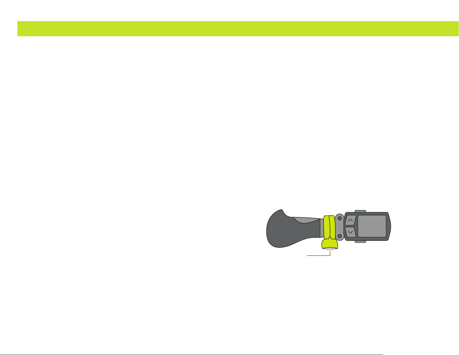
REMOVING THE THROTTLE
The throttle can easily be removed from the eBike if required
for Class 1 riding by following these steps :
Locate the throttle weatherproof twist connector (orange connection).
Unscrew the twist connect and gently pull to disconnect the throttle cable.
Loosen the securing bolt located under the throttle using a 3mm Allen key.
(Loosen the bolt enough to be able to freely manipulate the throttle
but not so much that the bolt falls out of the housing).
The handlebar grip will need to be removed in order to slide the throttle assembly off the end
of the handlebar. Ensure that the grip is reinstalled securely as an important safety precaution.
To re-install the throttle, repeat these steps in reverse while taking care to
properly line up the pins in the connection before applying any pressure.
BATTERY
All iGO batteries are secured to the bike frame using a barrel lock mechanism. The
battery can be removed from the frame for charging, storage, or when leaving the
bike in a public area by using the keys provided with the bike. Keys should always
be removed from the bike before riding. KEEP YOUR KEYS IN A SAFE PLACE.
It is advisable to keep a note of your key number with this manual for future reference.
The key number can be found on a metal tag attached with the keyring.
iGO DRIVE
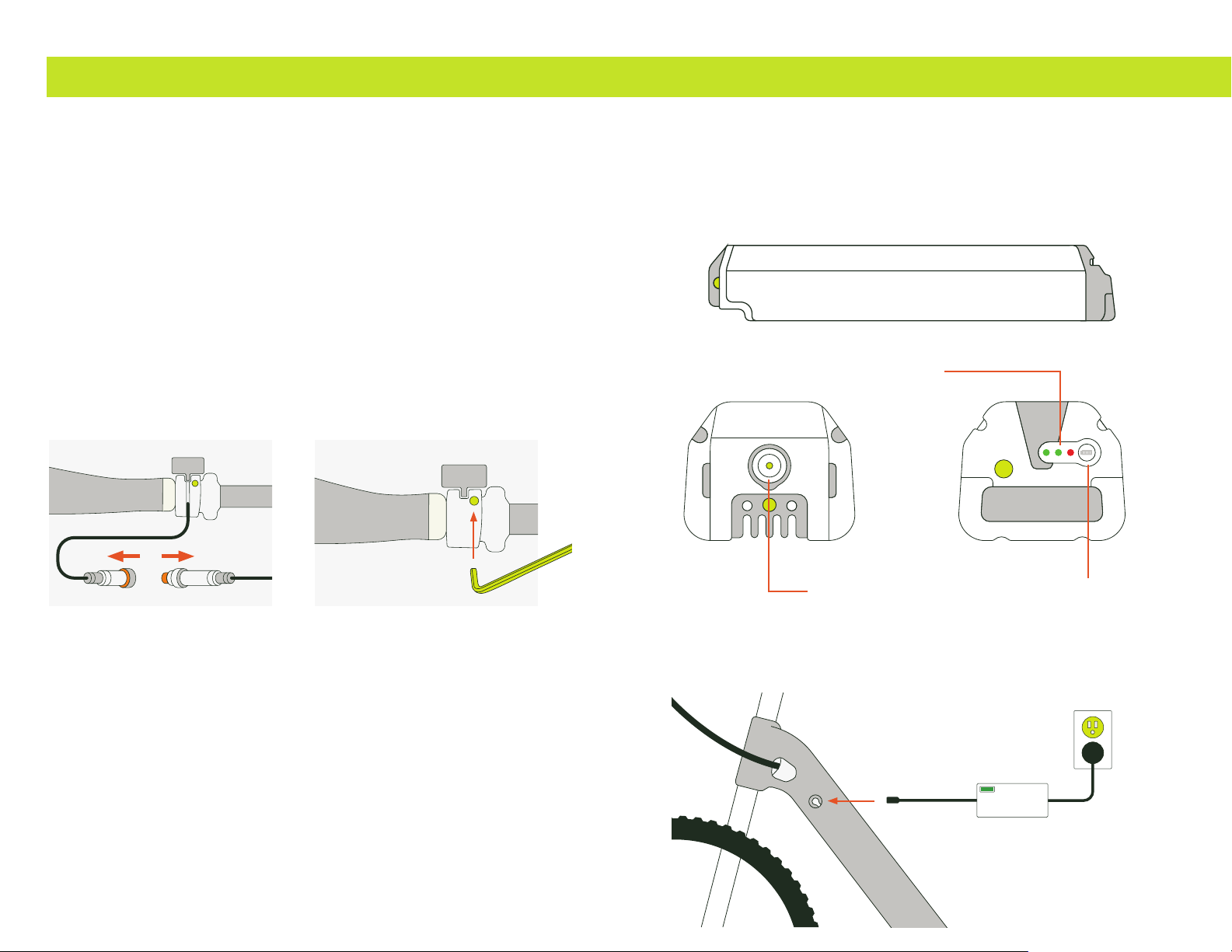
IDENTIFY THE BATTERY
The battery for the Discovery and Outland eBikes has the following features :
On frame battery charging port
The frame charging port is located on the top left side of the down tube (non-drive side).
Lift the charger port cover to gain access to the port to charge
the battery when it is installed in the bike.
CHARGING PORT
POWER METER
POWER METER BUTTON
16 17
iGO DRIVE
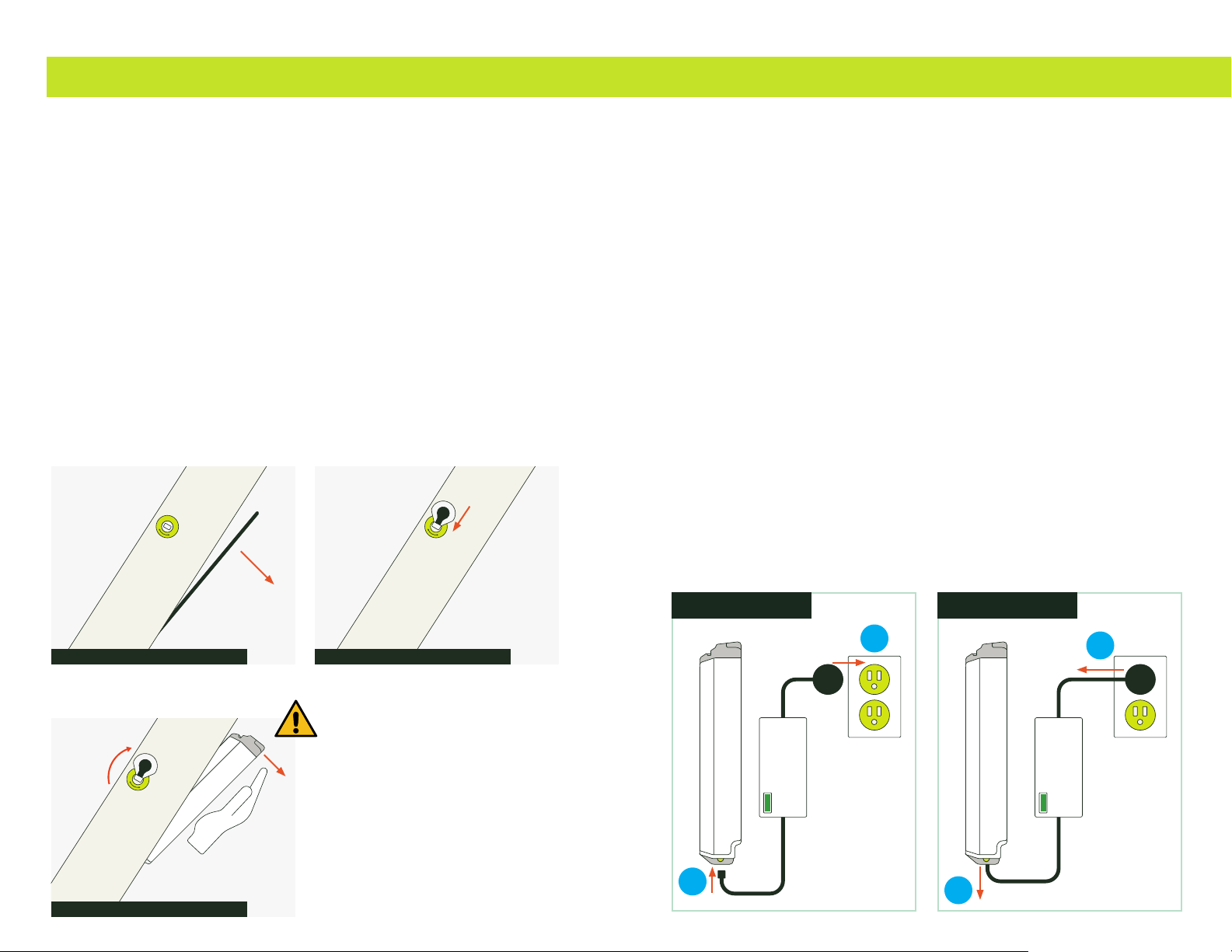
REMOVE / INSTALL BATTERY
To remove the battery from the bike frame rst remove the battery
cover under the battery tube by pushing down on the top latch and
tipping the top edge down on an angle, then lift and remove.
Insert the key into the lock but do not turn at this time. Support the battery with one
hand & use the other to turn the key 90˚ clockwise to the unlock position. While holding
the battery parallel to the frame carefully allow the battery to drop out of the frame.
To reinstall the battery, insert the key into the battery lock but do not turn at this time. Hold
battery parallel to frame and line up the battery with the receptacle. Insert the bottom portion
of the battery rst, and then with one hand turn the key 90˚ counter clockwise to the unlock
position. Push the top part of the battery into the receptacle until you hear the latch close
onto the battery. At this point the battery will hold itself in place. With both hands on each side
of the frame and thumbs under the battery case push the battery to make sure its locked and
secure.
Reinstall the battery cover by inserting the tab on the bottom part of the battery cover into the
slot located under the battery. Once inserted tilt the cover and latch into place.
Always lock battery & remove the key while riding.
CAUTION
When the key is turned the battery lock
will be released. The battery must be
supported to avoid falling from the frame.
CHARGING THE BATTERY
The battery can be charged both on and off of the bike.
It is important to follow these charging instructions in order :
1. Plug the chargers male plug into the battery/bike charging port.
2. Plug the charger into an approved 110 volt outlet.
DO NOT USE A POWER EXTENSION CABLE
The indicator LED on the charger will light green for a few seconds
and if a charge is necessary, the LED will turn red. The battery is fully
charged when the battery indicator LED becomes green.
When charging is complete :
1. Unplug the charger from the outlet rst.
2. Unplug the charger from the battery/bike.
YOU MUST ALWAYS CHARGE YOUR BATTERY WITH THE SUPPLIED
BATTERY CHARGER. FAILURE TO DO SO MAY RESULT IN FIRE, PERSONAL
HARM, DAMAGE TO PROPERTY YOUR BATTERY OR eBIKE
When the battery has become completely depleted you must charge it immediately. If the
cells are left depleted for a long period of time, they may become irreparably damaged.
Make sure to only charge the battery in a dry, well ventilated area.
Unplug the charger when the battery is fully charged, or when charger is not in use.
Do not throw an expired battery in the trash. Please recycle your
battery at an authorized recycling company in your area.
REMOVE BATTERY COVER INSERT KEY
SUPPORT BATTERY AND TURN KEY
UNPLUG
1
2
PLUG IN
2
1

18 19
iGO DRIVE
BATTERY RANGE AND CAPACITY
How far can I travel on my electric bike?
The total distance you can travel on your electric bike is not an easy amount to specify.
The range depends on many different factors including, but not limited to :
• The level of pedal assistance and throttle usage
• Resistance (wind, tire pressure, speed, inclines, road conditions and altitude)
• Total Weight (weight of the bike + rider + cargo)
• Outside Temperature
• The condition of the battery (battery capacity decreases as the battery ages)
Batteries are often compared based on capacity (Amp hours - Ah). However, a comparison
based on capacity alone does not properly depict a battery since the performance of
a battery pack is also based on battery voltage (V). The best way to compare battery
performance is by looking at the amount of energy that can be provided in watt-hours
(Wh). Wh takes into account both the capacity of the battery, as well as the average
voltage during discharge. Simply put, the higher the V/Ah, the higher Wh range.
Watt hours calculation : Battery voltage (V) x Amp hours (Ah) = Watt hours (Wh)
Every individual will have their own riding style and determine their own preference
for how much assist to use and when to engage this. The attainable distances will
likely be as varied and unique as the riders, even over the same terrain using the
same bikes. iGO only supply bikes with batteries that we condently believe will
allow sufcient range to sustain an active riding schedule between charges.
Efcient use of the gears while riding will greatly benet your
riding experience and extend battery range.
Tips to maximize eBike range
• Maintain your tire pressure in the recommended range as indicated on the tires.
• Minimize the use of throttle, especially hard acceleration from a standstill.
• Pedal while you are accelerating, especially from a stop.
• Slow down and enjoy the ride - higher speeds use a
proportionately greater amount of battery power.
• Lower the total weight of the rider and bike - carrying around
excess weight will use extra battery power.
• Frequent starts and stops require more energy than steady-state riding. We
recommend always obeying trafc signals, but if you can avoid pulling over
many times during a ride, you will be rewarded with a greater range.
• Use the correct gear. Shift gears so that your pedaling
cadence is maintained in the 70-90rpm range.
• A well-maintained bike is more efcient and will give greater range.
Correctly lubed chains, brakes that do not rub and well-maintained
wheel bearings will run much smoother and save battery energy.
IMPORTANT BATTERY SAFETY INFORMATION
DO NOT connect the positive terminal of the battery to the negative terminal.
DO NOT open your battery as it will void warranty.
The battery is sealed and therefore is rain resistant, however, DO NOT
expose your battery to repeated, continuous or excessive water ow.
Prolonged exposure to UV rays, rain and the elements may damage
the enclosure materials, store indoors when not in use.
Battery is not intended for use at elevations greater than 2000 m above sea level.
If you should encounter problems with your battery: remove the battery from
the bike and consult your authorized iGO retailer or iGO Support.
The performance of the battery will decrease at low temperatures.
Ideal operating temperature is approx. -10°C to 50°C. The guideline is that
the capacity will decrease by 1% at every 1°C of temperature drop.
DO NOT expose your battery to high temperatures (>50˚C), e.g. limit prolonged
storage in direct sunlight or in proximity to a direct heat source.
The battery is intended to be charged when the ambient temperature is between 0°C (32°F)
and 30°C (86°F). Never charge the battery when ambient temperatures are outside this range.
Make sure to only charge the battery in a dry, well ventilated area.
The socket-outlet shall be installed near the equipment and shall be easily accessible.
Unplug the charger when the battery is fully charged, or when charger is not in use.
Use ONLY the supplied charger.
Under ideal conditions, the battery pack can be recharged approximately 750 times. The
performance will slowly decrease over time and eventually will need to be replaced.
To maintain optimal performance of Lithium-ion batteries which need to be
stored for a long time and not used, they should be kept in a state of 50%-
60% charge. They should be recharged every 3 months and recharged every
half a year. Storage should be at moderate humidity levels and between 10°-
20°C. Elevated temperatures will increase the permanent loss of capacity.
The battery should be recycled properly at the end of its life. Please recycle
your battery at an authorized recycling company in your area.
20 21
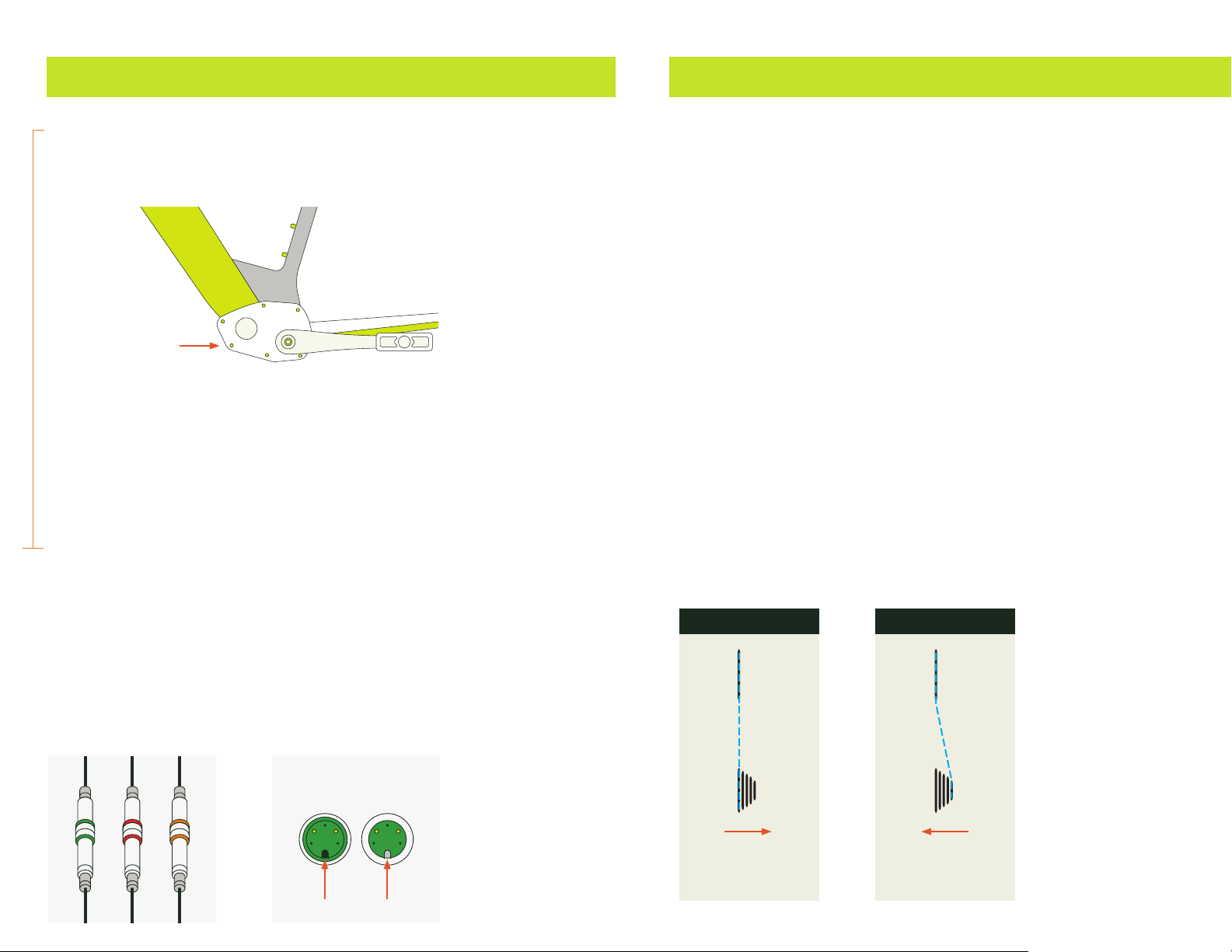
ELECTRONICS ACCESS PORT (EAP)
The Electronics Access Port gives easy access to the controller, wiring harness and sensor
array for the bicycle. It is located at the bottom bracket of the bike on the non drive side.
To access the port :
1. Loosen the 6 securing bolts located around the Access Port
cover using the correct sized Phillips head screwdriver.
2. Using a at head screwdriver or other at device, pry the cover off
(ensuring that you go all the way around the edge of the cover as to
not break any clamps or pins holding the cover in place).
3. Once the cover is loose, pull it towards you along the pedal shaft and
let it swing down, revealing the controller and wiring harness.
To replace the cover, simply repeat the above steps in reverse, ensuring
that you apply equal pressure around the cover to make sure it is
completely ush before tightening the securing bolts.
WEATHERPROOF CONNECTORS
Connection to the eBike peripheral components is by quick secure
weatherproof connectors. These plugs make for a secure, dry and truly
‘plug-and-play’ set-up for simple maintenance and customization.
For simplicity the following colors are used to identify the cables connecting :
red - Brakes
orange - Throttle
green - Display unit
When joining the weatherproof plugs take care to properly line up the pins in the connection
before applying any pressure. Turn the two connectors together to fully secure.
for : DISCOVERY ROSEMONT LE1 | DISCOVERY YORKVILLE LE1
iGO DRIVE
THE GROUPSET
A bike’s groupset refers to the mechanical parts that are involved in braking, changing gears,
or powering the drivetrain. This includes the shifter(s), brake levers, front and rear brake
calipers, front and rear derailleurs, wheel hubs, crankset, bottom bracket, chain, and cassette.
ABOUT GEARS AND SHIFTING
Understanding when and how to shift gears on any bike will lead to a smoother riding
experience and avoid unnecessary damage to components due to excessive strain. On
an electric bike efcient use of gears will also help to maximize your battery range.
Shifting gears is done so that you can maintain a constant and comfortable pedaling
speed (cadence), no matter how fast you are riding. As you move faster you will want to
use the shifters to ‘shift up’ into higher gears to stop your legs spinning too fast. As your
riding speed is reduced you will want to ‘shift down’ to lower gears so you do not have
to exert excessive pressure on the pedal to keep moving. When coming to a stop it is
recommended to ‘shift down’ to a lower gear. This positions the drivetrain so you will always
be ready to move off again in a lower (easier) gear and gradually ‘shift up’ through the gears
as you increase speed allowing you to safely gain momentum, traction and balance.
Ideally, scan the road ahead and anticipate your shifts. This will ensure that you are in the
correct gear when you need it, and avoid any problems with shifting under difcult conditions.
Note:
Always pedal forwards while shifting, the chain needs to be
moving in order to perform the gear shifts.
Try to avoid extreme strain on the chain when shifting, if you are pedaling very hard (uphill
or strong accelerations), ease up on the pedals slightly while continuing to pedal.
MECHANICAL COMPONENTS
shift up
into higher gears
LOW GEAR HIGH GEAR
shift down
into lower gears

22 23
MECHANICAL COMPONENTS
SHIMANO TRIGGER SHIFTERS
There are 2 levers on the shifter, A and B in the diagram :
Right side shifter
Push lever A with your thumb to ‘shift down’ when pedaling is too difcult.
This will move the chain to a larger gear on the rear wheel, and the indicator
on the shifter will show a lower number. Pedaling will be easier.
When speed increases and you are pedaling too fast, pull the lever B with your
index nger to ‘shift up’. This will move the chain to a smaller gear on the rear
wheel, and the indicator will show a higher number. Pedaling will be harder.
HOW TO BED IN NEW DISC BRAKE PADS
Properly bedding in your brakes will increase the lifespan of the pads,
reduce noise and increase the braking power. Before your rst ride, perform
this procedure to properly condition the brake pads and rotors :
1. Accelerate to a medium speed (approx. 20 km/h), then rmly apply the brakes
and reduce your speed to a walking pace. Repeat approximately 20 times.
2. Accelerate to a higher speed (approx. 32 km/h), then rmly and quickly apply the
brakes, reducing your speed to walking pace. Repeat approximately 10 times
3. Let the brakes cool before setting off on your rst ride.
DISC BRAKE ALIGNMENT
Disc brakes provide increased stopping power to ensure safe control of electric bicycles.
To properly adjust disc brakes you must rst make sure that the disc is properly aligned
within the brake caliper. To do this, loosen the top and bottom hex bolts with an Allen key.
Then maneuver the brake with your hand so that the disc passes
through the brake pads with minimal contact.
Once the disc rotates through the brake freely, retighten the hex bolts
and make sure that while tightening you maintain the alignment.
ADJUSTING HYDRAULIC DISC BRAKES
The hydraulic brake system on your iGO electric bike is self adjusting,
and will not require manual adjustment during normal operation.
If you pull the brake lever and the brakes fail stop your bike adequately, you
possibly have air in your brake line or the pads are worn past the usable limit.
In either case we strongly suggest this service be done by a professional
bike mechanic as special tools and procedures are required
DIAGRAM OF RIGHT SIDE SHIFTER
DIAGRAM SHOWING DISC BRAKE ALIGNMENT

24 25
ADJUSTABILITY AND iGO ERGOFIT
All iGO bikes are adjustable to suit individual riding position preferences.
iGO Bikes equipped with the Ergot system have toolless adjustable reach, pitch
and height allows riding posture to be adapted instantly at any time for :
• Maximum comfort and minimized muscle fatigue during long rides
• Adaptable riding styles (e.g. upright relaxed leisure to low+forward power riding)
• Ergonomically t different rider body types on the same bike
ADJUSTING THE SEAT HEIGHT
Your seat height should be adjusted properly to ensure you
get the most comfortable ride possible. The seat height
is properly adjusted when your knee has a slight bend
when sitting on the saddle with your foot on the pedal at
its lowest position. The seat height can be adjusted by
loosening the quick release lever on the seat tube clamp.
Retighten the quick release and check to make sure the
saddle is straight and held securely before riding again.
ADJUSTING THE SADDLE POSITION
You can tilt the saddle to change the seating angle, as well as adjust the fore/
aft position to suit your t. To adjust the saddle, loosen the bolt located on the
underside of the seatpost clamp, under the saddle, with an Allen key. You will be
able to move the saddle back and forth, and change the angle to suit your preferred
riding style. When you are done adjusting, make sure to retighten the bolt.
Note:
Ensure that the safety marks for max. height (written on the seat post)
are not visible when the seat clamp is secured, and that the rails on the
saddle are clamped by the seatpost only on the straight section.
When the saddle has been adjusted to your satisfaction be sure the
nose is pointing straight ahead and is not twisted to either side.
ADJUSTING THE HANDLEBARS (QUICK RELEASE)
The adjustable stem has an effective quick-release mechanism that will allow
you to unlock, adjust and retighten the stem and handlebar position.
To use, nd the lock button in the middle top of the stem and slide it forward to unlock
the main lever. While holding the button unlocked, lift the main lever fully up and rotate
towards the front of the bike. While fully opened, you will be able to adjust both the angle
of the stem and rotate the handlebars to achieve the most comfortable position.
When the handlebar is in the desired position, ensure it centered left and right in the
stem and close the main lever fully, ensuring you hear the lock button engage. Make sure
that the lock is engaged by pulling up on the main lever to verify that it does not open.
for : DISCOVERY YORKVILLE LE1 | DISCOVERY ROSEMONT LE1
INSTALLING THE HANDLEBARS (4 BOLT STEM)
Using the 4mm Allen key take off the 4 front bolts of the stem and remove the front plate.
Place handlebar in position on stem, replace the front plate reinstall the 4 bolts loosely.
Tighten bolts as shown; make sure to attach all bolts one at a time in order from 1
to 4 but don’t fully tighten until all bolts are installed (tighten to 5Nm - 6Nm).
for : DISCOVERY YORKVILLE LS1 | DISCOVERY ROSEMONT LS1
OUTLAND CABOT RS1 | OUTLAND SAWBACK RS1 | OUTLAND TORNGAT RS1
MECHANICAL COMPONENTS
DIAGRAM SHOWING SEAT CLAMP
26 27
REAR WHEEL REMOVAL AND INSTALLATION
Hub Motor equipped iGO electric bikes incorporate the drive motor, so
removal and re-installation requires a few special considerations.
First, shift the bike onto the smallest cog (highest gear) to make removal and installation
of the wheel easier. Next, locate and disconnect the cable that runs to the motor. Follow
the wire that exits the rear hub on the right side of the bike, you will see a weatherproof
connector partway between the hub and the pedal area. Disconnect this plug, either by
unthreading the outer collar and then pulling the 2 halves apart or by simply pulling apart.
Remove any cable ties or clips holding the wire to the frame. At this point, make sure to
have the bike supported in a work stand or inverted on the ground, allowing you to safely
remove the wheel. Loosen both nuts that hold the wheel onto the frame using an 18mm
wrench. These nuts may have a rubber cap installed, remove these rst. The wheel will be
free to drop out of the frame. Before removing the wheel completely, note the location
of the washers on the wheel axle so you can re-install them on the correct side of the
frame. We suggest taking a photo before disassembly to ensure correct reassembly.
When re-installing the wheel, rotate the axle so that the at sides insert into the dropouts
on the frame (a 10mm wrench will help to turn the axle to the correct orientation). Pay
attention to the brake rotor, make sure that it slides in between the brake pads on the brake
caliper. The chain should sit on the smallest gear, as it was when the wheel was removed.
Tighten the nuts hand-tight, then make sure that the wheel is sitting fully inserted
into the frame and the rim/tire is centered in the frame and not rubbing on either
side. Tighten the nuts to 25-30 Nm. Replug the motor wire connector, making
sure that the 2 halves are correctly oriented, and that the pins are straight and
clean. Re-thread the locking collar if present, and verify that the connection
is fully plugged in. Check the brake and shifter operation before riding.
TIRE PRESSURE
The tire pressure will affect the range and comfort of your bike. iGO recommends
that you always keep your tires at the designated pressure to ensure the best
ride. The recommended tire pressure is written on the sidewall of the tire.
Tire pressure is measured in P.S.I. (Pounds / Square Inch).
Make sure to use a tire pressure gauge when inating your
tires to ensure the correct tire pressure.
ADJUSTING THE SUSPENSION FORK
Many iGO electric bikes are equipped with a suspension fork with a lockout. By turning
the lever on the top of the right fork leg in the direction indicated, you are able to
‘lockout’, or stiffen up the fork for more efcient riding. The stiffness of the fork will
increase as the lever is turned further. Turning the lever to the limit will make the fork
completely rigid, which is useful for efcient riding on smooth roads. Turn the knob in
the opposite direction to take full advantage of the suspension to absorb the shocks
from rough roads, increase comfort and ensure your front wheel stays in better contact
with the road, providing more grip and condence when turning or braking.
On forks with adjustable preload, the left leg top
cap will be equipped with an adjuster knob that
will allow you to stiffen or soften the suspension
to suit your weight and comfort requirements.
On bikes equipped with an air suspension fork, the
air spring in the left leg can be adjusted with a shock
pump to make the fork stiffer or softer, according
to your weight and comfort requirements.
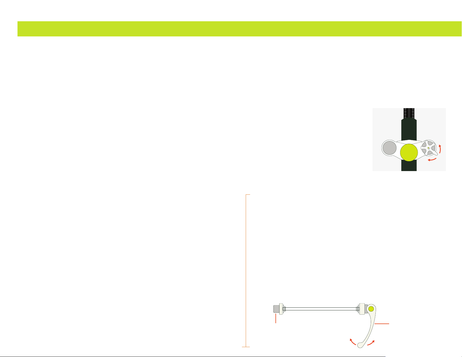
QUICK RELEASE, Q-LOC, AND THRU AXLE FORK
How to fasten the quick release hub
1. Move the quick release lever to the OPEN position and set the
wheel so it rmly touches the interior of the fork end.
2. Open and close the quick release lever with your right hand while gradually tightening
the adjusting nut clockwise with your left. Continue tightening the nut until you
feel resistance from the lever when it reaches parallel position with the hub
3. Grip the fork blade with your ngers and use the palm of your hand to apply
force to the quick release lever. It should take considerable force against to
tighten the lever completely. The word “CLOSE” inscribed in the lever should
face out. The lever should be in front of, and parallel to the fork blade
4. Note If the quick release lever can be easily pushed to the CLOSE position, this
means the clamping force is insufcient. Return the quick release lever to parallel
position with the hub and again turn the adjusting nut clockwise to increase the
clamping force. Push the quick release lever back to the CLOSE position.
5. If the clamping force is adjusted too strong and the quick release lever cannot
be pushed to the CLOSE position, turn the adjusting nut counter-clockwise to
reduce the clamping force. When doing this, do not over loosen the adjust nut.
Rotate the adjusting nut 1/8th of a turn then push the lever to CLOSE position.
Repeat this procedure until maximum clamping force is achieved by hand.
for : DISCOVERY YORKVILLE LE1 | DISCOVERY ROSEMONT LE1
DISCOVERY YORKVILLE LS1 | | DISCOVERY ROSEMONT LS1
MECHANICAL COMPONENTS
QUICK RELEASE LEVER
NUT
OPENCLOSE

28 29
Q-LOC assembly
1. Check the segmented ange is expanded before installation. Open the lever completely.
2. Slide in the axle until it “clicks”. Make sure the segmented ange is expanded.
3. Set the tension of the nut until the ange is ush with the dropout.
4. Close the lever completely. Check if it’s rmly seated. Re-tighten the nut if necessary.
Q-LOC removal
1. Open the lever completely.
2. Press and turn adjust nut clockwise until segmented ange retracts and stays latched.
3. Pull out the axle.
Axle assembly for front 15mm thru-axle
1. Position your front wheel into the dropouts of the lower fork leg. As you
are installing the front wheel, be sure to squarely position the brake rotor
in between the brake pads of the disc caliper. Thehub shouldersshould
seat squarely and rmly in thedropout counterbores.
2. Insert the axle into the left side of the fork dropout and slide it all the way
through the hub, until you contact theaxle nuton the other side.
3. Thread the axle into the axle nut and push the release lever back to the CLOSE position.
If the release lever can be easily pushed to the CLOSE position,
release the lever and continue to thread the axle nut until maximum
clamping force is achieved by hand when closing the lever.
for : OUTLAND CABOT RS1 | OUTLAND SAWBACK RS1
for : OUTLAND TORNGAT RS1
MECHANICAL COMPONENTS
PUSH
TURN
PUSH
TURN
+
_
PUSH
TURN

30 31
WHAT IS IGO ASSIST
iGO’s ever expanding knowledge base with guides, tips, and tricks to
optimize your experience through every step of your journey.
iGO Assist provides access to user manuals, assembly videos, FAQ, live chat and email/
phone support - iGO Assist can deliver everything you need to get on an electric bike for
the rst time; it will answer any questions you may have during your ride, and can share
expert tips and tricks to make sure you always get the most from your iGO electric bike.
If you still require further assistance you can submit a
support request through the iGO Assist portal.
HOW TO ACCESS IGO ASSIST
To access iGO Assist online visit :
assist.igoelectric.com
Chose from general FAQ, bike model specic documents and videos, chat
support, or ask detailed questions with ability to include photos that our
dedicated support team can use for to reference when responding.
To take full advantage of all iGO customer support options your eBike must be registered.
Advanced diagnostics
A wealth of in-depth diagnostic information (intended to speed up and simplify support
and servicing of your iGO electric bike) can be accessed through the iGO Ride app.
Should any advanced diagnostic information be required, the iGO support representative
or an iGO certied mechanic will identify and extract the relevant information for you.
The following pages provide some relevant information to assist in the
continued enjoyment and maintenance your new iGO eBike.
iGO ASSIST
DIAGNOSTICS AND WARNING CODES
If a diagnostic (warning/error) code appears on the eBike’s display unit,
identify the issue from this table and take the appropriate action.
If the code persists contact iGO support.
Diagnostic code Description Suggested action
1Synchronous motor signal overcurrent warning Check motor connections, unplug and ensure pins are
aligned correctly and the connection is fully secured.
2 Controller overcurrent warning Power off system and restart. Check controller
connections, unplug and ensure pins are aligned
correctly and the connection is fully secured.
3 Hall sensor signal warning Avoid stalling the motor. Check motor connections,
unplug and ensure pins are aligned correctly and the
connection is fully secured.
4 Brake lever sensor fault Check the weatherproof connector to the brake
cut-off sensor. Ensure pins are aligned correctly and
the connection is fully secured. Check brake lever for
damage and ensure lever retracts to the fully open
position.
5 Controller temperature warning Allow the controller to cool down for a short period
of time.
6 Motor temperature warning Allow the motor to cool down for a short period of
time.
8 Controller communication fault Verify cable harness and weatherproof connectors for
damage or disconnections.
9 Controller voltage warning Check condition of battery and battery connections.
Try a different battery if it is available.
10 Other faults Contact iGO Support
21 Controller overcurrent warning Power off system and restart. Check controller
connections, unplug and ensure pins are aligned
correctly and the connection is fully secured.
24 Hall sensor signal warning Avoid stalling the motor. Check motor connections,
unplug and ensure pins are aligned correctly and the
connection is fully secured.
25 Brake lever sensor fault Check the weatherproof connector to the brake
cut-off sensor. Ensure pins are aligned correctly and
the connection is fully secured. Check brake lever for
damage and ensure lever retracts to the fully open
position.
28 Regional settings warning Perform system update.
30 Communication fault Check the display cable and weatherproof connector
to the display unit. Ensure pins are aligned correctly
and the connection is fully secured. Verify cable
harness and weatherproof connectors for damage or
disconnections.
31 Regional settings warning Perform system update.
36 Torque value fault Power off system and restart without putting
pressure on the pedals.

32 33
iGO ASSIST
PART DESCRIPTION
FRAME Hydroformed Aluminum Hybrid 48cm (19”) ERGOFIT
COLOR Black
FORK SUNTOUR NEX-DS700C suspension with lockout, quick release
SHIFTERS SHIMANO ALTUS 8-speed
CHAINRINGS 42T Narrow Wide teeth
CHAIN KMC E8-S
REAR DERAILLEUR SHIMANO ACERA 8-speed
CASSETTE SHIMANO ACERA 8-speed 11-32T
HANDLEBAR 640mm, 16mm rise, 31.8mm dia.
STEM Toolless adjustable threadless, 0 to 90 degree rise
SEAT POST 31.6mm, quick release (350mm)
SADDLE SELLE ROYAL Rio
BRAKE LEVERS TEKTRO HD-E350
BRAKE CALIPERS TEKTRO HD-E350 hydraulic disc
ROTORS 180mm
TIRES 27.5”x2.4”
RIMS 27.5” dual wall alloy, black
DISPLAY 2” TFT LCD Display
MOTOR 500W geared rear hub motor, 48V
TORQUE up to 55Nm
CONTROLLER 48V high power FOC, Uart/Can
BATTERY 5000mAh SAMSUNG Cell Lithium-Ion 48V / 15Ah / 720Wh
RANGE 110km (69mi) *
PAS 5 Levels of power assisted pedaling
THROTTLE Any time on demand thumb throttle - removable
SENSOR Electronic 32 pulse Cadence Sensor
CHARGER 48V, 2A, DC, UL Certied
CHARGING TIME 4 to 6 hours
CLASS MULTI-CLASS SWITCHABLE : Class2 / Class1 optional / Class3 capable where permitted **
BIKE WEIGHT 25.7kg (56.7 lbs)
BATTERY WEIGHT 3.5kg (7.7 lbs)
WEIGHT CAPACITY 125 kg (275 lbs)
Specications subject to change
MAIN TECHNICAL PARAMETERS, SPECIFICATIONS, AND PARTS
DISCOVERY YORKVILLE LE1 SKU : 100-221-001
*Actual range may vary depending on Ah of battery rider weight and other riding conditions.
**Electric bike class regulation:
Class 1 : No throttle function, PAS with maximum speed 32km/h (20mph)
Class 2 : Throttle and PAS maximum speed 32km/h (20mph)
Class 3 : Throttle maximum speed 32km/h (20mph), PAS maximum speed 45km/h (28mph)
all classes allow a maximum motor power of 750W(US) or 500W(Canada)
PART DESCRIPTION
FRAME Hydroformed Aluminum Step Through 45.7cm (18”) ERGOFIT
COLOR Off White
FORK SUNTOUR NEX-DS700C suspension with lockout, quick release
SHIFTERS SHIMANO ALTUS 8-speed
CHAINRINGS 42T Narrow Wide teeth
CHAIN KMC E8-S
REAR DERAILLEUR SHIMANO ACERA 8-speed
CASSETTE SHIMANO ACERA 8-speed 11-32T
HANDLEBAR 630mm, 21mm rise, 31.8mm dia.
STEM Toolless adjustable threadless, 0 to 90 degree rise
SEAT POST 31.6mm, quick release (350mm)
SADDLE SELLE ROYAL Rio
BRAKE LEVERS TEKTRO HD-E350
BRAKE CALIPERS TEKTRO HD-E350 hydraulic disc
ROTORS 180mm
TIRES 27.5”x2.4”
RIMS 27.5” dual wall alloy, black
DISPLAY 2” TFT LCD Display
MOTOR 500W geared rear hub motor, 48V
TORQUE up to 55Nm
CONTROLLER 48V high power FOC, Uart/Can
BATTERY 5000mAh SAMSUNG Cell Lithium-Ion 48V / 15Ah / 720Wh
RANGE 110km (69mi) *
PAS 5 Levels of power assisted pedaling
THROTTLE Any time on demand thumb throttle - removable
SENSOR Electronic 32 pulse Cadence Sensor
CHARGER 48V, 2A, DC, UL Certied
CHARGING TIME 4 to 6 hours
CLASS MULTI-CLASS SWITCHABLE : Class2 / Class1 optional / Class3 capable where permitted **
BIKE WEIGHT 25.9kg (57.1 lbs)
BATTERY WEIGHT 3.5kg (7.7 lbs)
WEIGHT CAPACITY 125 kg (275 lbs)
Specications subject to change
MAIN TECHNICAL PARAMETERS, SPECIFICATIONS, AND PARTS
DISCOVERY ROSEMONT LE1 SKU : 100-211-001
*Actual range may vary depending on Ah of battery rider weight and other riding conditions.
**Electric bike class regulation:
Class 1 : No throttle function, PAS with maximum speed 32km/h (20mph)
Class 2 : Throttle and PAS maximum speed 32km/h (20mph)
Class 3 : Throttle maximum speed 32km/h (20mph), PAS maximum speed 45km/h (28mph)
all classes allow a maximum motor power of 750W(US) or 500W(Canada)

34 35
iGO ASSIST
PART DESCRIPTION
FRAME Hydroformed Aluminum Hybrid 48cm (19”)
COLOR Platinum
FORK WB suspension with lockout, quick release
SHIFTERS SHIMANO ALTUS 8-speed
CHAINRINGS 42T Narrow Wide teeth
CHAIN KMC E8-S
REAR DERAILLEUR SHIMANO ALTUS 8-speed
CASSETTE SHIMANO ALTUS 8-speed 11-32T
HANDLEBAR 640mm, 45mm rise, 31.8mm dia.
STEM 80mm, 7 degree rise
SEAT POST 31.6mm (350mm)
SADDLE SELLE ROYAL Rio
BRAKE LEVERS TEKTRO HD-E350
BRAKE CALIPERS TEKTRO HD-E350 hydraulic disc
ROTORS 180mm
TIRES 27.5”x2.4”
RIMS 27.5” dual wall alloy, black
DISPLAY 2” TFT LCD Display
MOTOR 350W mid motor, 36V
TORQUE up to 80Nm
BATTERY 5000mAh SAMSUNG Cell Lithium-Ion 36V / 15Ah / 540Wh
RANGE 90km (56mi) *
PAS 5 Levels of power assisted pedaling
THROTTLE Any time on demand thumb throttle - removable
SENSOR Internal Torque, Cadence, Speed
CHARGER 36V, 2A, DC, UL Certied
CHARGING TIME 4 to 6 hours
CLASS MULTI-CLASS SWITCHABLE : Class2 / Class1 optional / Class3 capable where permitted **
BIKE WEIGHT 25.5kg (56.2 lbs)
BATTERY WEIGHT 3.5kg (7.7 lbs)
WEIGHT CAPACITY 125 kg (275 lbs)
Specications subject to change
MAIN TECHNICAL PARAMETERS, SPECIFICATIONS, AND PARTS
DISCOVERY YORKVILLE LS1 SKU : 100-222-001
*Actual range may vary depending on Ah of battery rider weight and other riding conditions.
**Electric bike class regulation:
Class 1 : No throttle function, PAS with maximum speed 32km/h (20mph)
Class 2 : Throttle and PAS maximum speed 32km/h (20mph)
Class 3 : Throttle maximum speed 32km/h (20mph), PAS maximum speed 45km/h (28mph)
all classes allow a maximum motor power of 750W(US) or 500W(Canada)
PART DESCRIPTION
FRAME Hydroformed Aluminum Step Through 45cm (17.7”)
COLOR Burgundy
FORK WB suspension with lockout, quick release
SHIFTERS SHIMANO ALTUS 8-speed
CHAINRINGS 42T Narrow Wide teeth
CHAIN KMC E8-S
REAR DERAILLEUR SHIMANO ALTUS 8-speed
CASSETTE SHIMANO ALTUS 8-speed 11-32T
HANDLEBAR 640mm, 45mm rise, 31.8mm dia.
STEM 80mm, 7 degree rise
SEAT POST 31.6mm (350mm)
SADDLE SELLE ROYAL Rio
BRAKE LEVERS TEKTRO HD-E350
BRAKE CALIPERS TEKTRO HD-E350 hydraulic disc
ROTORS 180mm
TIRES 27.5”x2.4”
RIMS 27.5” dual wall alloy, black
DISPLAY 2” TFT LCD Display
MOTOR 350W mid motor, 36V
TORQUE up to 80Nm
BATTERY 5000mAh SAMSUNG Cell Lithium-Ion 36V / 15Ah / 540Wh
RANGE 90km (56mi) *
PAS 5 Levels of power assisted pedaling
THROTTLE Any time on demand thumb throttle - removable
SENSOR Internal Torque, Cadence, Speed
CHARGER 36V, 2A, DC, UL Certied
CHARGING TIME 4 to 6 hours
CLASS MULTI-CLASS SWITCHABLE : Class2 / Class1 optional / Class3 capable where permitted **
BIKE WEIGHT 25.3kg (55.8 lbs)
BATTERY WEIGHT 3.5kg (7.7 lbs)
WEIGHT CAPACITY 125 kg (275 lbs)
Specications subject to change
MAIN TECHNICAL PARAMETERS, SPECIFICATIONS, AND PARTS
DISCOVERY ROSEMONT LS1 SKU : 100-212-001
*Actual range may vary depending on Ah of battery rider weight and other riding conditions.
**Electric bike class regulation:
Class 1 : No throttle function, PAS with maximum speed 32km/h (20mph)
Class 2 : Throttle and PAS maximum speed 32km/h (20mph)
Class 3 : Throttle maximum speed 32km/h (20mph), PAS maximum speed 45km/h (28mph)
all classes allow a maximum motor power of 750W(US) or 500W(Canada)

36 37
iGO ASSIST
PART DESCRIPTION
FRAME Hydroformed Aluminum Hardtail 27.5 MTB 49cm (19.3”)
COLOR Celeste and Black
FORK SUNTOUR SF-18 27.5” XM34-DS-Boost-LO suspension with lockout, Q-Loc thru axle
SHIFTERS SHIMANO ALTUS 8-speed
CHAINRINGS 34T Narrow Wide teeth
CHAIN KMC E8-S
REAR DERAILLEUR SHIMANO ALTUS 8-speed
CASSETTE SHIMANO ALTUS 8-speed 11-32T
HANDLEBAR 720mm, 28mm rise, 31.8mm dia.
STEM 45mm with 3 degree rise, 31.8mm clamp dia.
SEAT POST 31.6mm (350mm)
SADDLE SELLE ROYAL
BRAKE LEVERS TEKTRO HD-E350
BRAKE CALIPERS TEKTRO HD-E350 hydraulic disc
ROTORS 180mm
TIRES 27.5”x2.4”
RIMS 27.5” dual wall alloy, black
DISPLAY 2” TFT LCD Display
MOTOR 500W mid motor, 48V
TORQUE up to 130Nm
BATTERY 5000mAh SAMSUNG Cell Lithium-Ion 48V / 15Ah / 720Wh
RANGE 70km (45mi) *
PAS 5 Levels of power assisted pedaling
THROTTLE Any time on demand thumb throttle - removable
SENSOR Internal Torque, Cadence, Speed
CHARGER 48V, 2A, DC, UL Certied
CHARGING TIME 4 to 6 hours
CLASS MULTI-CLASS SWITCHABLE : Class2 / Class1 optional / Class3 capable where permitted **
BIKE WEIGHT 27.4kg (60.4 lbs)
BATTERY WEIGHT 3.5kg (7.7 lbs)
WEIGHT CAPACITY 125 kg (275 lbs)
Specications subject to change
MAIN TECHNICAL PARAMETERS, SPECIFICATIONS, AND PARTS
OUTLAND SAWBACK RS1 SKU : 100-322-201
*Actual range may vary depending on Ah of battery rider weight and other riding conditions.
**Electric bike class regulation:
Class 1 : No throttle function, PAS with maximum speed 32km/h (20mph)
Class 2 : Throttle and PAS maximum speed 32km/h (20mph)
Class 3 : Throttle maximum speed 32km/h (20mph), PAS maximum speed 45km/h (28mph)
all classes allow a maximum motor power of 750W(US) or 500W(Canada)
PART DESCRIPTION
FRAME Hydroformed Aluminum Trekking 49cm (19.3”)
COLOR Green and Black
FORK Suntour XCM32 HLO DS suspension with lockout, Q-Loc thru axle
SHIFTERS SHIMANO ALTUS 8-speed
CHAINRINGS 42T Narrow Wide teeth
CHAIN KMC E8-S
REAR DERAILLEUR SHIMANO ALTUS 8-speed
CASSETTE SHIMANO ALTUS 8-speed 11-32T
HANDLEBAR 720mm, 28mm rise, 31.8mm dia.
STEM 45mm with 3 degree rise, 31.8mm clamp dia.
SEAT POST 31.6mm (350mm)
SADDLE SELLE ROYAL
BRAKE LEVERS TEKTRO HD-E350
BRAKE CALIPERS TEKTRO HD-E350 hydraulic disc
ROTORS 180mm
TIRES 27.5”x2.4”
RIMS 27.5” dual wall alloy, black
DISPLAY 2” TFT LCD Display
MOTOR 500W mid motor, 48V
TORQUE up to 130Nm
BATTERY 5000mAh SAMSUNG Cell Lithium-Ion 48V / 15Ah / 720Wh
RANGE 95km (60mi) *
PAS 5 Levels of power assisted pedaling
THROTTLE Any time on demand thumb throttle - removable
SENSOR Internal Torque, Cadence, Speed
CHARGER 48V, 2A, DC, UL Certied
CHARGING TIME 4 to 6 hours
CLASS MULTI-CLASS SWITCHABLE : Class2 / Class1 optional / Class3 capable where permitted **
BIKE WEIGHT 23.3kg (51.4 lbs)
BATTERY WEIGHT 3.5kg (7.7 lbs)
WEIGHT CAPACITY 125 kg (275 lbs)
Specications subject to change
MAIN TECHNICAL PARAMETERS, SPECIFICATIONS, AND PARTS
OUTLAND CABOT RS1 SKU : 100-233-101
*Actual range may vary depending on Ah of battery rider weight and other riding conditions.
**Electric bike class regulation:
Class 1 : No throttle function, PAS with maximum speed 32km/h (20mph)
Class 2 : Throttle and PAS maximum speed 32km/h (20mph)
Class 3 : Throttle maximum speed 32km/h (20mph), PAS maximum speed 45km/h (28mph)
all classes allow a maximum motor power of 750W(US) or 500W(Canada)

38 39
iGO ASSIST
PART DESCRIPTION
FRAME Hydroformed Aluminum Fatbike 48cm (19”)
COLOR Red and Black
FORK RST RENEGADE 26” suspension with lockout, thru axle
SHIFTERS SHIMANO ALTUS 8-speed
CHAINRINGS 34T Narrow Wide teeth
CHAIN KMC E8-S
REAR DERAILLEUR SHIMANO ALTUS 8-speed
CASSETTE SHIMANO ALTUS 8-speed 11-32T
HANDLEBAR 700mm, 28mm rise, 31.8mm dia.
STEM 75mm with 3 degree rise, 31.8mm clamp dia.
SEAT POST 31.6mm (350mm)
SADDLE SELLE ROYAL
BRAKE LEVERS TEKTRO HD-E350
BRAKE CALIPERS TEKTRO HD-E350 hydraulic disc
ROTORS 180mm
TIRE (front) front specic 26”x4.8”
TIRE (rear) rear specic 26”x4.8”
RIMS 26”x95mm Fat bike rim
DISPLAY 2” TFT LCD Display
MOTOR 500W mid motor, 48V
TORQUE up to 130Nm
BATTERY 5000mAh SAMSUNG Cell Lithium-Ion 48V / 15Ah / 720Wh
RANGE 60km (37mi) *
PAS 5 Levels of power assisted pedaling
THROTTLE Any time on demand thumb throttle - removable
SENSOR Internal Torque, Cadence, Speed
CHARGER 48V, 2A, DC, UL Certied
CHARGING TIME 4 to 6 hours
CLASS MULTI-CLASS SWITCHABLE : Class2 / Class1 optional / Class3 capable where permitted **
BIKE WEIGHT 26.9kg (59.3 lbs)
BATTERY WEIGHT 3.5kg (7.7 lbs)
WEIGHT CAPACITY 125 kg (275 lbs)
Specications subject to change
MAIN TECHNICAL PARAMETERS, SPECIFICATIONS, AND PARTS
OUTLAND TORNGAT RS1 SKU : 100-322-301
*Actual range may vary depending on Ah of battery rider weight and other riding conditions.
**Electric bike class regulation:
Class 1 : No throttle function, PAS with maximum speed 32km/h (20mph)
Class 2 : Throttle and PAS maximum speed 32km/h (20mph)
Class 3 : Throttle maximum speed 32km/h (20mph), PAS maximum speed 45km/h (28mph)
all classes allow a maximum motor power of 750W(US) or 500W(Canada)
PART SCREWS / BOLTS TORQUE VALUE
Rear derailleur mount bolt
cable screw
8 - 10 Nm
5 - 7 Nm
Gear lever mount bolt 5 Nm
Cassette lockring 40 Nm
Crank mount bolt 45 - 50 Nm
Pedal pedal axle 25 - 35 Nm
Saddle seat post with 1 tting block
seat post with 2 tting blocks
22 Nm
12 Nm
Seat post clamp 5 - 7 Nm
Stem faceplate
steerer
5 Nm
6 - 8 Nm
Grips clamp screw 2 - 3 Nm
Rack mount screw to the frame 5 Nm
Fender mount bolt on the fork
mount bolt on the rack/frame
5 Nm
5 Nm
Kickstand bolt 6 - 8 Nm
Brake lever handlebar mount screw 4 - 5 Nm
Disc brake rotor screw 4 Nm
Brake caliper mount bolt 5 - 7 Nm
TORQUE TABLE
The following table provides the recommended torque values for components.
Ensure all fasteners are tightened carefully and checked regularly. Use
of a torque wrench is advised to check values are correct.
Never exceed the recommended torque values.
Some components may have torque values indicated on the part.
Always respect the indicated recommended values.
This manual suits for next models
6
Table of contents
Other I-GO Scooter manuals


