i-MO ACF5 Installation instructions

ACF/UCF5 2019.12 en-GB, ID-No.: 163-044/B
Original Operating Manual
Before commencing any work, read this instruction carefully! Failure to comply with
these instructions may cause damage and personal injury!
!
Screw pumps
ACF/UCF 5
Contents Page
Introduction 2
Safety 2
Pump identication 4
Installation 5
Start-up 10
Trouble shooting 12
Maintenance and Service 14
List of components 14
Exploded View/Ordering code 15
Service intervals 16
Dismantling and reassembling the pump 17
Dismantling 18
Reassembly 21
www.northridgepumps.com

2www.imo.se
ACF/UCF5 2019.12 en-GB, ID-No.: 163-044/B
ATTENTION
ATTENTION
Safety
The manufacturer accepts no liability for damages caused by disregarding any of the documentation.
Intended use
• Only use the pump to pump the agreed pumped liquids (→ order data sheet).
• Adhere to the operating limits.
• Avoid dry running:
– Make sure the pump is only operated with, and never without, pumped liquid.
• Avoid cavitation:
– Open the pressure-side tting completely.
• Avoid damage to the motor:
– Do not switch on themotor more that themaximumpermissible number of times per hour (→ manufac-
turer’s specications).
• Consult the manufacturer about any other use of the pump.
• Pumps delivered without a motor must be assembled into a pump unit according to the provisions of
EC Machine Directive 2006/42/EC.
Prevention of obvious misuse (examples)
• Note the operating limits of the pump with regard to temperature, pressure, viscosity, ow rate and motor
speed (→ order data sheet).
• When using auxiliary systems, ensure there is a continuous supply of the appropriate operating medium.
• Do not operate the pump while the pressure-side tting is closed.
• Only select the setup type according to this operating manual. For example, the following are not allowed:
– Hanging pumps in the pipe
– Overhead installation
– Installation in the immediate vicinity of extreme heat or cold sources
General safety instructions
Observe the following regulations before carrying out any work.
Product safety
The pump has been constructed according to the latest technology and recognized technical safety rules.
Nevertheless, operation of the pump can still put the life and health of the user or third parties at risk or dam-
age the pump or other property.
• Only operate the pump if it is in perfect technical condition and only use it as intended, remaining aware of
safety and risks, and adhere to the instructions in this manual.
Document Purpose
ATEX additional instructions Operation in explosion-hazard areas
Order data sheet Technical specications, conditions of operation
Technical description Technical specications, operating limits
Supplier documentation Technical documentation for parts supplied by
subcontractors, e.g. drive system, coupling or
auxiliary operating system.
Spare parts list Ordering spare parts
Declaration of conformity Conformity with standards,
Content of the declaration of conformity
Other applicable documents
Introduction
www.northridgepumps.com

3www.imo.se
ACF/UCF5 2019.12 en-GB, ID-No.: 163-044/B
• Keep this manual and all other applicable documents complete, legible and accessible to personnel at all
times.
• Refrain from any procedures and actions that would pose a risk to personnel or third parties.
• In the event of any safety-relevant malfunctions, shut down the pump immediately and have the malfunc-
tion corrected by the personnel responsible.
• In addition to the entire documentation for the product, comply with statutory or other safety and accident-
prevention regulations and the applicable standards and guidelines in the country where the system is oper-
ated.
Obligations of the operating company
Safety-conscious operation
• Ensure that the following safety aspects are observed and monitored:
– Intended use
– Statutory or other safety and accident-prevention regulations
– Safety regulations governing the handling of hazardous substances
– Applicable standards and guidelines in the country where the pump is operated
• Make personal protective equipment available.
Qualied personnel
• Make sure all personnel tasked with work on the pump have read and understood this manual and all other
applicable documents, especially the safety, maintenance and repair information, before they start any work.
• Organize responsibilities, areas of competence and the supervision of personnel.
• Ensure that all work is carried out by specialist technicians only:
– Fitting, repair and maintenance work
– Work on the electrical system
• Make sure that trainee personnel only work on the pump under the supervision of specialist technicians.
Safety equipment
• Provide the following safety equipment and verify its functionality:
– For hot, cold and moving parts: on-site safety guards for the pump
– For possible electrostatic charges: provide the necessary grounding
– If there is no pressure relief valve in the pump: Provide an appropriate safety valve on the pressure
side between the pump and the rst shut-off device
Warranty
• Obtain the manufacturer’s approval prior to carrying out any modications, repairs or alterations during the
warranty period.
• Only use genuine parts or parts that have been approved by the manufacturer.
Drive system
For pumps delivered without a drive system, comply with the following requirements for the drive system:
• When using three-phase asynchronous motors, observe IEC 60034-30-1.
• Power of the drive according to EN ISO 5199 is recommended (EN ISO 5199 also applicable for drives of
screw pumps).
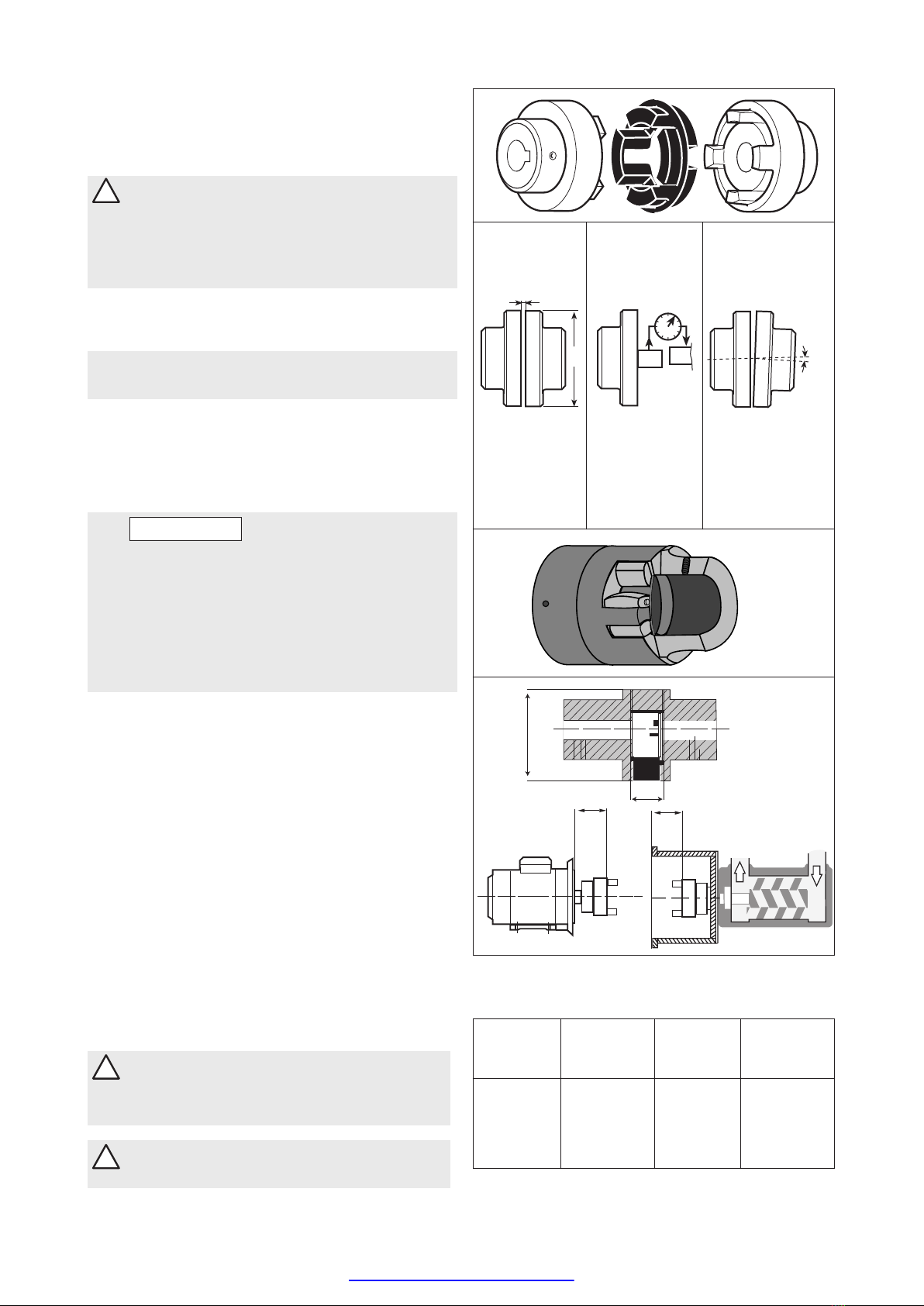
• For stub shaft coupled pumps (LPD and ACD) connect motor and stub shaft directly.
• For other series use elastic coupling according to DIN 740-2.
• Use coupling guard with the following requirements:
– Fastening elements must be connected to the pump unit in undetachable design (cannot get lost).
– Safety distances against the reaching of hazardous areas according to EN ISO 13857 must be
complied with.
Obligations of the operating company
• All directions given on the pump must be followed (and kept legible), e.g. the arrow indicating the sense of
rotation and the markings for uid connections.
• Pump, coupling guard and components:
– Do not step on them or use as a climbing aid
– Do not use them to support boards, ramps or beams
– Do not use them as a xing point for winches or supports
– Do not use them for storing paper or similar materials
– Do not use hot pump or motor components as a heating point
– Do not de-ice using gas burners or similar tools
• Do not remove the safety guards for hot, cold or moving parts during operation.
• Use personal protective equipment whenever necessary.
• Only carry out work on the pump while it is not running.
• Isolate the motor from its supply voltage and secure it against being switched back on again when carrying
out any tting or maintenance work.
• Reinstall the safety equipment on the pump as required by regulations after any work on the pump.
www.northridgepumps.com

4www.imo.se
ACF/UCF5 2019.12 en-GB, ID-No.: 163-044/B
These instructions are valid for all low pressure pumps as specied in the Pump identication chart below.
Pump identication
LPQ
ACF/UCF
ACG/UCG
ACE
LPE
ACD
LPD 015
020
025
025
032
038
045
052
060
070
080
090
100
110
125
100
110
125
140
N
L
N
D
K
N
K
L
N
L
N
P
1
6
3
7
5
1
I
N
N
N
I
N
V
V
T
V
T
V
T
T
B
B
B
B
F
B
F
Y
P
P
E
P
E
P
P
A101
A101
A327
A020
A385
A020
A084
A087
A101
P
J
(4)
(4)
025
032
038
D
K
L
N
D
K
L
N
3 NV
TB
YA101
P
I
NR
T
Pump name Rotor
lead
(1)
Shaft-
seal
design
(1)
Mounting
(2)
Valve
(3)
Also
valid for
option
Comments
Pumpunit
without shaft
coupling
(1) See Product description or Service instruction for specied pump
model
(2) B = Flange mounting
F = Foot mounting
Y = Vertical foot mounting
(3) E = Without valve
G = Valve with external return
P = Valve with internal return for total pressure range
(4) Valid for UCF
Option
A020 Pump with surface treated casing(s)
A084 Pump with lifetime greased ball bearing
A087 Pump with CCW-rotation and lifetime greased ballbearing
A101 Pump with CCW-rotation, when not standard
A327 Pump with Tuning®
A328 Pump with Tuning®
A385 A101 + A327
Material
pump-
body
(1)
Size
(1)
Design
modi-
cation
Pumpunit
without shaft
coupling
Specic hazards
Explosion-hazard area
• (→ ATEX additional instructions).
Hazardous pumped liquids
• Observe the safety regulations for handling hazardous substances (e.g. hot, ammable, poisonous or po-
tentially harmful) when handling hazardous pumped liquids.
• Use personal protective equipment when carrying out any work on the pump.
• Noise level:
– Check individual pump series noise level in respective Product Description
www.northridgepumps.com

5www.imo.se
ACF/UCF5 2019.12 en-GB, ID-No.: 163-044/B
Fig. 2 Lifting of pump
max 90°
min 60°
PD[
PLQ
!Failure to comply with these instructions
may cause damage and personal injury!
Transport and storage
Always protect the pump against ingress of water
and other impurities. Store the pump in a clean,
dry and warm environment. The pump is delivered
with the internals oiled and with protective covers
over the pipe connections and drain openings.
These covers should remain in place for as long
as possible during the mounting and installation
procedure but must be removed before start up.
!All work carried out on the pump has to
be performed in such a manner that risks
for personal injury are observed!
Lifting of pump
!All pumps should be lifted with straps
securely attached to the pump or pump
unit, so that the center of gravity is
located between the straps in order to
avoid tipping of the pump.
Use two eye bolts (M 20) securely fastened to the
front cover for pump LPQ. Pump and connecting
frame are lifted together using two eye bolts
securely fastened to the top of the connecting frame.
(Thread dimension is M 16, except for frame size
600, where it is M 20).
Identification of safety instructions
Non compliance of saf
ety instructions
identified
by the following symbol -
could aff
ect safety for persons.
Safety instructions where
electrical safety is involved,
are identified by:
Safety instructions which shall be considered fo
r
reasons of safe operation of the pump or pump
unit and/or protection of the pump or pump unit
itself are marked by the sign: ATTENTION
PD[
PLQ
Fig. 1 Clean and dry environment.
Installation
BEFORE COMMENCING ANY WORK, READ THIS INSTRUCTION CAREFULLY!
Design limitations and technical data for each pump are found in the Product description.
Installation of IMO AB low pressure pumps does not require special skills. However, these instructions
presume that the work is carried out by experienced tters.
Maintenance and service instructions, which are specic for each pump are presented after the
installation instructions.
www.northridgepumps.com

6www.imo.se
ACF/UCF5 2019.12 en-GB, ID-No.: 163-044/B
Fig 4. Distance between coupling halves.
(IMO AB standard coupling)
Outer diameter Distance between Outer diameter Distance between
of coupling coupling halves of coupling coupling halves
(D mm) (t mm) (D mm) (t mm)
A B A B
50 26 2.0 8 148 3.5
67 40 2.5 16 168 3.5
82 55 3.0 18 194 3.5
97 65 3.0 20 214 4.0
112 80 3.5 24 240 4.0
128 95 3.5 26
Fig. 3 Alignment of the IMO AB standard coupling
t
max
0.1°
D
See table below An angular
misalignment of
0.1° corresponds
to approx. 0.2 mm
deviation/100 mm.
Angular
alignment
Distance
between
coupling halves
Circular
run-out
A
X
Y
x = y - t
Ø D
t
B
Lifting of the complete pump unit with the lifting
device attached to the motor, should be avoided
as the motor’s lifting provisions may not be able to
carry the combined weight of the pump and motor.
!Lifting a complete pump unit, using
slings or hooks attached to the pump
or connecting frame may be dangerous
since the centre of gravity of the pump
unit may be higher than the points of
attachments.
Mounting
For pumps in explosion-hazard areas
(→ ATEX additional instructions).
The pump must be securely mounted on a rm
stable foundation and positioned so that it is easily
accessible for inspection and servicing.
Provisions for collecting oil spillage when servicing
the pump should be considered.
ATTENTION
The installation must always be designed
to minimise damage. Should an
operational or functional failure occur.
E.g. precautions should be considered to
collect oil spillage due to a broken pipe
or pump housing, to stop pump operation
if overheating should occur or if the oil
volume is below a minimum tank level.
Alignment and shaft couplings
The pump shall be connected to its driver via a
exible shaft coupling. Pumps of type ACG/UCG
and ACF/UCF may also be driven via gears or
pulleys as specied in the Product Description,
provided the radial forces are kept within the
specied range.
An angular misalignment of 0.1° corresponds to
approx. 0.2 mm deviation/100 mm.
The coupling and alignment shall be selected not to
transmit any axial or radial loads on the shaft ends.
IMO AB standard couplings shall have a distance
between the coupling halves as per table, g 4. the
coupling halves shall be secured by lock screws.
For other types of couplings, please refer to
respective maker’s manual.
! When tting the shaft coupling, do not
use a hammer or similar as this may
damage the ball bearing and shaft seal.
Use some kind of press tool.
!When handling liquids that may harm skin
use gloves and/or protective clothing.
www.northridgepumps.com

7www.imo.se
ACF/UCF5 2019.12 en-GB, ID-No.: 163-044/B
Fig. 8 Deaeration
Fig.7 Suction line
Fig. 6 Pipe connections
For direct driven pumps the alignment between
pump and motor shafts must be kept within the
following limits:
Max run-out Max angular
misalignment
(mm) (degrees)
Type LPD
and ACD (n/a short coupled)
Other types 0.3 0.1
Fig 5.
!When handling liquids which may involve
re hazards appropriate precautions to
avoid danger are to be taken.
!Measures shall be provided to avoid
accidental contact with the rotating shaft
coupling. Any installed coupling guard
shall permit easy access to the pump
shaft for maintenance and inspection of
the pump bearing and seal housing.
Pipe connections
The pipe work shall be installed and supported so
that no pipe stresses are transfered to the pump
body.
The pipe work should be tight in order to avoid
leakage and inltration of foreign particles and/or air.
Shut off valves should be installed in both suction
and discharge pipes, so that the pump can be
hydraulically isolated.
Suction line
The suction pipe should be designed so that the
total pressure drop, measured at the pump inlet
ange, does not exceed the suction capability of the
pump.
Make a proper calculation of the suction line
including components such as valves, strainer,
pipe bends etc. Generally, the pressure drop in the
suction line should be as low as possible, which is
achieved if the suction pipe is short, straight and has
a suitable diameter.
The velocity in the suction line should be kept in the
range 0.5 - 1.2 m/s. For L.O. circulating systems, we
recommend to keep it as low as possible.
The suction line must be equipped with a port that
allows lling the pump before start.
Discharge line
The discharge line should be dimensioned to keep
the velocity in the range 1 - 3 m/s.
Deaeration
In installations with negative suction head, where
the pump might be started against a pressurized
system, a deaeration pipe with an orice (2-3 mm
recom mended) has to be installed. The deaeration
pipe should be connected to the outlet pipe’s highest
point.
This must also be installed when the pump is used
as an stand-by pump.
www.northridgepumps.com

8www.imo.se
ACF/UCF5 2019.12 en-GB, ID-No.: 163-044/B
Fig. 11 Liquid trap
Fig. 9 Strainer
Strainer
The pump has to be protected from foreign matter,
such as weld slag, pipe scale, etc., that could enter
the pump via the suction line. If the cleanliness of
the system cannot be guaranteed, a strainer must
be installed in the inlet pipe near the pump. For
practical reasons a suction strainer with 0.6 mm
mesh openings is recommended:
The size of the strainer should be selected so that
it is large enough to allow adequate pressure at the
pump inlet. The pressure drop across the strainer
should preferably not exceed 0.1 bar at max. ow
rate and normal operating viscosity. A vacuum
gauge between the strainer and the pump inlet is
recommended to indicate when the strainer needs
cleaning.
Note: The service life of the pump is decisively
inuenced by the degree of contamination of the
uid being conveyed, that means, by the number,
size and hardness of the abrasive components.
Shaft seal drain
The pump should be installed so that any leakage
from the shaft seal does not become a hazard. As
the shaft seal has to be lubricated a small amount of
oil dripping cannot be avoided.
Provisions to collect the leakage from the shaft seal
must be made.
A drain pipe can be connected to the drain
connection on the pump, (not applicable to pump
series LPD). However, when pumping heavy fuel
oil or any other liquid that is likely to become very
viscous at ambient temperature, we recommend
that the liquid is allowed to drop freely from the drain
opening.
Liquid trap
In some mounting arrangements the pump may not
retain the liquid at stand still. In such installations the
suction pipe should be arranged so it forms a liquid
trap together with the pump, keeping the pump half
lled with liquid. See g. 11.
Fig. 10 Shaft seal drain
www.northridgepumps.com

9www.imo.se
ACF/UCF5 2019.12 en-GB, ID-No.: 163-044/B
bar
Fig. 12 Gauges
Gauges
Gauges for monitoring the pump’s working
conditions are recommended. These gauges should
be placed readable as close to the pump’s in- and
outlet anges as possible. On standard pumps,
series ACE, LPE, ACG/UCG, ACF/UCF and LPQ,
there are gauge connections for both in- and outlet.
Pressure relief valve
All systems with screw pumps should be equipped
with a pressure relief valve installed immediately
adjacent to the pump.
In the standard versions of IMO AB low pressure
pumps, this pressure relief valve is an integral part
of the pump to protect the pump against excess
pressure.
This relief valve is intended for momentary
protection of the pump against overpressure. It is
neither intended to be a system pressure control
device, nor used as a ow regulation device.
When liquid is circulated through the valve it is
heated up in proportion to the set pressure level and
the percentage of by-passed liquid.
Up to 50 % by-pass can generally pass for unlimited
periods of time without harming the pump except
when pumping low viscosity media.
If more than 50% recirculation is anticipated, a value
specic to each application should be determined by
closely monitoring the pump body temperature.
For ow less than ~50 m3/h
- 100% by-pass can only be tolerated for less
than about 3 minutes, provided the viscosity &
temperature is within the limit of the pump type.
For ow higher than ~50 m3/h
- 100% by-pass is tolerated less than 30 seconds.
Note that an open valve can cause noise.
If the pump is operating in line with a separate
pressure control valve (see g. 14), the setting of the
relief valve should be high enough to not to interfere
with the control valve.
Likewise, if two pumps are operating in parallel, the
setting should be such that interference between the
two valves is avoided.
Pressure testing and ushing
The system must be ushed and pressure tested
before connecting the pump. If corrosive liquid, such
as water is used, the system must be thoroughly
drained, dried and protected against corrosion after
having been ushed.
! Oil leakage may make the oor slippery
and cause personal injury.
Fig. 13 Pressure relief valve
Fig. 14 External control with pressure relief valve
www.northridgepumps.com

10 www.imo.se
ACF/UCF5 2019.12 en-GB, ID-No.: 163-044/B
IMO AB
Fig. 15 Filling the pump
Fig. 17 Direction of rotation
Fig. 16 Deaeration plugs
ACG
ACF
ACE
Deaeration plug
Deaeration plug
Deaeration plugs
Deaeration plug
LPQ
Start-up
For pumps in explosion-hazard areas
(→ ATEX additional instructions).
Before starting
After installation and whenever it can be assumed
that the pump has been emptied, the pump must be
thoroughly lled with liquid. See g 15.
For ACE Generation 3, LPE Generation 3, ACG
Generation 7 and ACF Generation 4 delivered after
1997, ACF Generation 5 and LPQ the pumps have
been tted with deaeration plugs making venting of
the shaft seal compartment easy before start-up.
In installations with positive suction pressure: After
opening the inlet and outlet valves, simply open the
deaeration plug a few turns until oil sips out. Tighten
the plug.
In installation with negative suction pressure: After
opening the inlet and outlet valves, remove the
deaeration plug and ll the shaft seal compartment
with oil. Fit and tighten the plug. See g. 16.
Note: for LPQ the amount of oil is appr 50 liter.
!Make sure the prime mover is locked out
and can not be started accidentally.
Rotate the shaft by hand while lling the pump, to
ensure that the rotor bores and the shaft seal cavity
is lled. On the smaller pumps: (LPD, ACD, ACE,
LPE, ACG/UCG), this is done by rotating the fan on
the electric motor after removing the fan cover.
! Do not forget to t the motor fan cover
again before making start of motor
possible.
On the ACF/UCF and LPQ pumps, the pump can
be turned using the shaft coupling. If the suction
pipe cannot be completely lled, it is important to
ensure that the trapped air is evacuated without any
pressure build up. (See g. 8 Deaeration).
ATTENTION
Starting a dry pump is likely to cause
damage, especially to the shaft seal.
Direction of rotation
When the pump is ready to be started, switch the
motor briey on and off and check that the drive
motor rotates in the correct direction as indicated by
the rotation arrow.
The arrow is placed on different spots depending on
the pump series.
www.northridgepumps.com

11www.imo.se
ACF/UCF5 2019.12 en-GB, ID-No.: 163-044/B
Fig. 18 Adjusting the tuning
a minimum. On a double acting pump like the LPQ
pump, there are two tuning valves, which must be
adjusted individually.
Setting of tuning of the LPQ:
1. Before starting the setting check that both setting
screws (8 mm socket head cap screw on the
discharge side) are closed.
2. Turn the lower screw until the noise level obtains
a minimum.(If turned too much the noise will
increase again).
3. Turn the upper screw and continue to reduce
the noise level. (If turned too much the noise will
increase again).
4. Repeat item 2. and 3. in order to achieve the
lowest possible noise level.
Setting of tuning of the ACG/UCG and ACF/UCF:
1. Before starting the setting, check that the setting
screw (8 mm: ACG/UCG, 12 mm: ACF/UCF,
socket head cap screw on the discharge side)
are closed.
2. Turn the screw CCW until the noise level
becomes the lowest (if turned too much the noise
will increase again).
Once set, the tuning needs no further adjustment,
providing the operating conditions stay the same.
NOTE: It´ s not possible to accidentally turn the
tuning spindle too far.
!If operating temperature exceeds 60°C
(149°F), appropriate measures to avoid
skin contact shall be provided.
!Use hearing protections whenever high
noise can be expected from pump, motor
and/or environment.
ATTENTION
Don’t mix up with arrow for inlet and
outlet!
Starting
Check that all valves necessary for the operation
are fully opened in both discharge and suction lines.
The rst time, the pump should be started with
the adjusting spindle of the pressure relief valve
tightened to half of the available turns (the valve
setting is increased when the spindle is turned
clockwise).
By monitoring the pressure gauge it can be
determined when the suction line is primed and
the pump begins to work. Should the pump not
operate normally soon after start, stop the pump
within half a minute. Start again after about 3-5
minutes (the shaft seal must have time to cool off)
and run for half a minute. This procedure may need
to be repeated a couple of times if the suction line
is extremely long. Should the pump still not work, it
must be assumed there is a problem in the system
that needs to be remedied. Check the suction line
calculation on page 5 and/or see ”Trouble shooting”,
page 10.
!Pumps with external ball bearing
including grease nipple, must be
regreased after one hour of running, while
the pump is operating
Setting the pressure relief valve
To set the opening pressure;
Tighten the valve spindle by rotating clockwise
to the maximum extent. The system pressure is
regulated by throttling an external valve to required
value. The pressure relief valve is eased until the
pressure is just beginning to decrease by turning the
spindle CCW. The internal relief valve is now preset
for desired opening pressure. Open the throttling
external valve entirely.
As standard, the recommended valve setting is 1
bar above system pressure.
NOTE: The set screw on LPD is hidden behind a
plate.
Adjusting the tuning
The tuning adjustment, which is a standard feature
on ACF/UCF and LPQ (option on ACG/UCG pumps,
is a device for minimizing the effects of dissolved
and free air in lube oil systems. The tuning principle
is described in the Product Description.
The tuning should be adjusted while the pump is
working under normal operating conditions. This is
done by turning the tuning spindle with an Allen key
(size 8 mm for ACG/UCG , 12 mm for ACF/UCF and
LPQ ) to a position where the noise level comes to
www.northridgepumps.com

12 www.imo.se
ACF/UCF5 2019.12 en-GB, ID-No.: 163-044/B
Trouble shooting
Reverse the terminal
connection on electric motor.
Connecting and discon-
necting of electric cables
must be done only by
personnel authorized to
do such work.
See above.
Check all components
in suction line. The inlet
condition should be checked
with a vacuum gauge at the
pump inlet.
Check the suction line.
See the chapter on Deaera-
tion (see page 5).
See above.
Readjust the pressure relief
valve to a value above
counter pressure.
Readjust the pressure relief
valve.
Check all components in the
suction line (strainers, valves
etc.).
See the chapter on Noise
and Vibration. ( Page 11).
Readjust the pressure relief
valve.
Check the components in the
discharge line inclusive the
recipients.
Check the valve. See
Maintenance and Service
instruction for respective
pump.
Check all components in the
suction line (strainers, valves
etc.).
See the chapter on Noise
and Vibration. ( Page 11).
Contact your IMO AB
representative.
- Electric cables to motor
wrongly connected.
- Wrong direction of rotation.
- Suction line is not open or
pressure drop in the suction
line is too high.
- Major air leakage into the
suction line.
- The pump cannot evacuate
the air through the discharge
line due to excessive counter
pressure.
- The pump is not primed.
- The pressure relief valve is set
below the counter pressure.
- The pressure relief valve is set
too low (Discharge pressure
also low).
- Something is restricting the
ow in the suction line. (This
would usually cause noise).
- The pumped liquid contains
a signicant amount of com-
pressible gas, such as free
air. (This would usually cause
noise).
- The pressure relief valve is set
too low.
- Counter pressure in the
discharge line is too low due to
a major leakage.
- The valve piston is stuck in
open position.
- Something is restricting the
ow in the suction line. (This
would usually cause noise).
- The pumped liquid contains
a signicant amount of com -
-pressible gas, such as free
air. (This would usually cause
noise).
- A too small pump has been
chosen.
Wrong direction of rotation
What to doProblem Cause
No ow
Flow too low
Pressure too low
The pump cannot be primed
www.northridgepumps.com

13www.imo.se
ACF/UCF5 2019.12 en-GB, ID-No.: 163-044/B
What to doDisturbance Cause
Pressure too high
Drive motor difcult to start
or tends to stop by tripping
the motor overload relay
Noise and vibrations
!Monitor the pump
function and shut
down if any sign
of malfunction is
noticed.
- The pressure relief valve is set
too high.
- The oil is too cold (or
has higher viscosity than
anticipated).
- Counter pressure in the
discharge line is too high.
- Counter pressure too high.
- Liquid too cold
- Motor is undersized for the
prevailing conditions.
- Electrical power supply faulty.
- Motor overload relay set too
low or is faulty.
- Incorrect setting of Y/D starter.
- The ow to the pump is
insufcient.
- Insufcient support of pipe
work.
- Bad alignment
- Air leakage into the suction
line.
- Free air in the liquid or gas
cavitation.
- Faulty electrical supply.
Readjust the pressure relief
valve.
Reduce the pressure setting
until operational temperature
has been reached.
Check the discharge line.
See above: Pressure too high.
Readjust the pressure relief
valve to a lower value. Thus
the power consumption for
the pumping is relieved and
overloading due to the high
viscosity may be avoided.
When the liquid has reached
normal temperature and thus
ows easily, the relief valve is
reset to normal pressure.
Check the motor.
Check the motor and motor
connection.
Readjust or replace the relay.
Readjust the setting of the
starting sequence. The time
before the motor overload
relay is tripped should not
exceed 10-15 seconds.
See chapter: The ow is too
low.
Check for pipe vibrations in
the pump connections. Check
that the pipes are sufciently
clamped.
Check alignment, see page 4.
Check the suction line for air
leakage.
For pumps with Tuning:
Adjust the Tuning. If this does
not help or for pumps without
Tuning: Contact your IMO
representative or IMO service
dept.
Check all three phases of the
supply.
www.northridgepumps.com

14 www.imo.se
ACF/UCF5 2019.12 en-GB, ID-No.: 163-044/B
Explanations:
ACF: Pump with
DIN anges
UCF: Pump with
ANSI anges
CW: Clockwise
rotation
CCW: Counter
clockwise
rotation
G011: Rotor set
CCW rotation
G012: Rotorset CW
rotation
G050: Compl shaft
seal
G053: Minor kit
(G050+G057)
G054: Major kit
G057: Joint kit
G070: Valve ele-
ment
Included components in Spare part sets
Pos Part Denomination Qty G011 G012 G050 G053 G054 G057 G070
1010 Complete power rotor (CCW-rot.) 1 x x
1020 Complete power rotor (CW-rot.) 1 x x
(103) Ball 1 (x) (x)
(104) Spring 1 (x) (x)
(105) Hole screw 1(x) (x)
(106) Balancing piston 1(x) (x)
113 Key 1 x x
122 Ball bearing 1 x x x
130 Support ring 1 x x x
131 Retaining ring 1 x x x
201 Idler rotor (CCW-rotation) 2 x
202 Idler rotor (CW-rotation) 2 x x
401 Pump body 1
4240 Tuning element 1
(424) Cover 1
(424A) Gasket 1 x x x
(425) Screw 4
(429) Guiding screw 1
(429A) Tension pin 1
(430) Piston 1 (Valid for sizes 100-125) 1
(432) Tension pin (Valid for sizes 100-
125) 1
(437) O-ring 1 x x x
451 Screw 4
451A Washer 4
453 Screw 8
455 Screw 4
455A Washer 4
462 Plug 1
462A Washer 1 x x x
463 Plug 1
463A Washer 1 x x x
480 Valve housing 1
501 Front cover 1
506 O-ring 1 x x x
509 Mechanical seal 1 x x x
520 Compl. cover 1
520A O-ring 1 x x x
(520B) Tension pin 1
521 Screw 4
521A Washer 1
(537) Plug 1
(537A) Washer 1 x x x
556 Gasket 1 x (x) x
6000 Valve cartridge 1 x
(6010) Compl. valve cover 1 (x)
(602) Pin 1 (x)
(603) O-ring 1 x x (x) (x)
(605) O-ring 1 x x (x) (x)
(608) Valve spindle 1 (x)
(609) Washer 1 (x)
(610) Ball bearing 1 x (x)
(612) Regulating nut 1 (x)
(614) Valve piston 1 (x)
(615) Spring 1 (x)
(622) Nut 1 (x)
(623) Ball bearing 1 x (x)
List of components
Valid for all ACF and UCF Generation 5 pumps with leads and sizes: 080, 090, 100 K5/N5 & 110, 125 L5/N5.
With version codes: ITBP & NTBP. Also valid with options A020, A078, A101.
Maintenance and Service
For pumps in explosion-hazard areas (→ ATEX additional instructions).
www.northridgepumps.com

15www.imo.se
ACF/UCF5 2019.12 en-GB, ID-No.: 163-044/B
437
429
429A
425
4240
463
463A
424A
401
UCF4 mechanical seals xVxx differ from UCF5 seal version xTxx,
i.e. not interchangeable.
506 501 451A
451
521A
521
537
537A
509
1020
106
122
520A
130131
105
104
103
202
462A
462
614
608
612
603
609
610
605
623
622
520 520B
453
480 556
615
602
6010
455A
455
Pump size
Pos 080 090 100 110 125
G011 Rotor set N-lead 192966 192968 192970 192972 192974
CCW K-lead 192967 192969 192971
L-lead 192973 192975
G012 Rotor set N-lead 192785 192958 192960 192962 192964
CW CW K-lead 192786 192959 192961
L-lead 192963 192965
G050 Shaft seal xTxx 194659 194659 194660 194660 194660
G053 Minor kit xTxx 194661 194662 194663 194664 194665
G057 Joint kit 192990 193101 192991 193103 192992
G070 Valve xxxP 192553 192553 192554 192554 192555
G099 Complete IEC 132 901195015 901195014
shaft IEC 160 901195004 901195004 9011950 08 9011950 08 901195008
coupling IEC 180 901195005 901195005 9011950 09 9011950 09 9011950 09
IEC 200 901195006 901195006 901195010 901195010 901195010
IEC 225 9011950 07 901195011 901195011 901195011
IEC 250 901195012 901195012 901195012
IEC 280 901195013 901195013 901195013
Kit Contents To be used
for
G057 Gaskets, o-rings,
ball bearing, etc Dismantling
of the pump
G053 G057 + Shaft
seal G050 Normal
scheduled
inspection
G054 G053 + Complete
rotor set Repair after
major break-
down or great
wear
Recommended
Spare Parts Kits
Every shutdown for service of a plant
is costly. The time for repair should
therefore be limited to a minimum which
can be accomplished by keeping a
spare pump. The changed pump can
later be repaired at a suitable place and
can then be used as a spare pump. For
maintenance the following spare parts
kits are recommended:
Mechanical seal valid for both ACF5
and UCF5 xTxx seal versions.
Ordering Code
Exploded view
Introduction
A screw pump from IMO is a quality product that is designed for a long problem free operation in tough environ-
ments. As all other mechanical products they do however require a certain grade of maintenance and service in
order to guarantee a faultless and economic favourable operation.
For ACF: Note that former version of mechanical seal, called xVxx has been replaced by xTxx. The seals are 100%
interchangeable and since Januari 2016, version xVxx is obsolete.
For UCF: UCF4 mechanical seals xVxx differ from UCF5 seal version xTxx, i.e. not interchangeable.
www.northridgepumps.com

16 www.imo.se
ACF/UCF5 2019.12 en-GB, ID-No.: 163-044/B
Service intervals
The intervals for inspection and replacement of wear
parts vary greatly with the properties of the pumped
liquid and can only be determined by experience. All
internal parts of the ACF/UCF-pump are lubricated by
the pumped liquid.
Pumping liquid which contain abrasive materials, or
liquid that is corrosive, will signicantly reduce service
life and call for shorter service intervals.
Wear in the pump will normally show as:
▪Vibration
▪Noise
▪Loss of capacity
▪Reduction in ow/pressure
• Leakage
We recommend planned inspection and overhaul at
regular intervals, not exceeding 3 years.
It is recommended to always have the spares included
in minor spare part kit G053 available for a planned
inspection.
Inspection of rotors
To reach the idler rotors in a quicker way than described
in the dismantling section, loosen the rear cover (480)
with valve. Screw out the idler rotors backwards. Inter-
nal clearances in the pump, which are vital for its proper
function, may have been affected by wear. Acceptable
wear can be determined only by experience of the
actual application. As a rule of thumb the following max
clearance values may apply: Between rotor and bores:
0.2 mm, Between rotor anks: 0.4 mm For light duties
(low pressure, medium viscosity) even bigger clear-
ances may be acceptable but for low visc./high pres-
sure duties the limit will be lower. Also watch if there are
major scratches on these parts.
Inspection of shaft seal
As the seal faces of a mechanical shaft seal are
lubricated by the uid a certain leakage will always
be present. Ten drops per hour can be considered as
acceptable. An external visual inspection of the pump
is advisable at least every two days to assure that the
shaft seal is not leaking too much.
Excessively leaking shaft seals should be changed
without delay, as the leakage normally will grove worse
and cause additional damage.
Follow the instructions in the dismantling/reassembly
session. When working with a shaft seal, cleanliness is
of outmost importance. Avoid touching the seal faces.
If necessary, the seal faces should be cleaned imme-
diately prior to assembly, using a dust free cloth and
clean solvent.
Warranty matters
IMO AB´s warranty obligations covers new pumps for 1
year after the commissioning of the pump.
Parts that NOT are covered by the warranty are normal
wear details such as the mechanical shaft seal, the ball
bearing or the exible coupling.
Precautions prior to
starting maintenance on
the pump
2 If the pumps operating temperature
exceeds 60°C, let the pump cool off before
any service, maintenance or dismantling
work is commenced to avoid burn injury
3 All work carried out on the pump has to be
performed in such a manner that risks for
personal injury are observed!
4 When handling liquids that may harm skin,
use gloves and/or protecting clothing!
5 When handling liquids which may involve
re hazard appropriate precautions to
avoid danger are to be taken.
6 In case of failure for system with elevated
pressure, uid jets may cause injury and/
or damage.
7 Oil leakage may make the oor slippery
and cause personal injury.
8 Before any maintenance work, ensure that
the driver is deenergized and the pump
hydraulically isolated.
9 Connecting and disconnecting of electrical
cables must be done only by personnel
authorized to do such work.
www.northridgepumps.com

17www.imo.se
ACF/UCF5 2019.12 en-GB, ID-No.: 163-044/B
ACF 5 © IMO AB
d
D
GREASE
L
A B C D E F G H I
509 451 51A 501 506
462
462A
614
(608)
(615)
A
(612)
(609)
(610)
(605)
(603)
(602)
(601)
(6010)
463A
463
455A
455
(623)
(622)
6000
A
131 130 122 B-B (105)
(104)
(103)
521 521A 520A
537
537A
113
B
(520B)
5200
520
A(106) 1020 A-A 202 401 556 453 480
B
Sizes 080-090
C-C
4240
(425)
(429)
(437)
(424) Sizes 100-125
(424A) (429A)
(432)
(430)
)
010)
0
)
)
1:4
4
1:4
List of tools necessary for dismantling and reassembly
A = Slide calliper
B = Screw driver
D = Crow bar
E = Plastic mallet
F = Puller
G = Allen key
H = Pairs of pliers
I = Mounting sleeve
J = Oil can
Sectional View
Dismantling and reassembling the
pump
Mounting sleeve
dimensions (mm)
Pump
size d L D
080 46 155 62 ±3
090 46 155 62 ±3
100 66 180 85 ±4
110 66 180 85 ±4
125 66 180 85 ±4
www.northridgepumps.com

18 www.imo.se
ACF/UCF5 2019.12 en-GB, ID-No.: 163-044/B
A
A
1:1
ACF5 © IMO AB
ON
OFF
Dismantling
A.
For most installations repair can be done with the
pump in place by removing the motor.
▪Turn the electricity OFF.
▪Close the valves.
▪Disconnect the electric motor.
▪For horizontal installation drain the pump by
loosen screws 453 3-4 turns and loosen 480
valve housing.
10 Use appropriate vessels to collect oil
spillage when operating the pump
11 Pump and/or motor should be lifted
with straps securely so that the
centre of gravity is located in order to
avoid tipping
B.
▪Loosen and remove screws 521
▪Pull out the power rotor 1020 with the help of
coupling half or an eye bolt tted in the power
rotor
12 Be careful when the threaded part
of the rotor passes the bore in the
cover
C.
▪Note the axial position of the coupling half
▪Release the stop screw
D.
▪Remove the coupling half with a puller
www.northridgepumps.com

19www.imo.se
ACF/UCF5 2019.12 en-GB, ID-No.: 163-044/B
520
S4,5,6
131
130
▪Press down the complete stationary part of the
shaft seal S1 & S2 out the end cover 520 by
means of a Teon piece that ts smoothly.
▪NOTE: The other end of the Teon piece should
t on the opposite side of S1 and is used lager on
when S1 is pressed into the end cover 520 again.
E.
▪Remove the key 113
F.
▪Pull the cover 520 upwards
▪Loosen set screws that lock S5 to shaft. Care-
fully slide the rotary shaft seal components S4,
S5 & S6 upwards.
G.
▪Remove the circlip 131 with a plier.
▪Remove the washer 130.
H.
▪Remove the ball bearing 122 from the rotor
1020 with a three legged puller.
I.
www.northridgepumps.com

20 www.imo.se
ACF/UCF5 2019.12 en-GB, ID-No.: 163-044/B
J.
• Loosen the bolts 451 and remove the front-
cover 504 with its o-ring 506 from the pump
body 401.
M.
▪Remove
the cylindrical spring loaded pin 429a with a
suitable puncher.
▪Unscrew the tuning piston 429 counter-clock-
wise from the cover 4420.
K.
• Carefully slide the idle rotors out of the Pump
body.
• Loosen the bolts 425 and pull the complete tun-
ing device straight upwards.
N.
▪Change o-ring 437 on the tuning piston 429 and
mount it in 4240 in reverse order.
L.
▪Unscrew the valve counter clockwise as far as
possible in order to release the spring tension
before commencing any works with valve as the
spring tension otherwise can cause personal
injury
▪Loosen the 4 bolts 455 & 455a in order to pull
out the complete valve insert.
▪Reassemble in opposite order.
▪Loosen the 8 bolts 453 in order to remove the
back cover 480.
▪Reassemble in opposite order.
www.northridgepumps.com
Other manuals for ACF5
1
This manual suits for next models
1
Table of contents
Other i-MO Water Pump manuals

i-MO
i-MO CIRCOR D12DZ-250 User manual

i-MO
i-MO ACE3 Series User manual

i-MO
i-MO ACG Manual

i-MO
i-MO CIRCOR OptiLine ACE4 Installation instructions

i-MO
i-MO CIRCOR BK6DHZ(C)-250 User manual

i-MO
i-MO OptiLine LPE4 Installation instructions

i-MO
i-MO OptiLine ACG8 Installation instructions

i-MO
i-MO ACF5 Manual

i-MO
i-MO D4 Manual

i-MO
i-MO CIRCOR GLH8L-400 Series User manual