i-PRO WV-QEM506 User manual

1
• Before attempting to connect or install this product, please read these instructions carefully
and save this manual for future use.
• The external appearance and other parts shown in this manual may differ from the actual
product within the scope that will not interfere with normal use due to improvement of the
product.
i-PRO Co., Ltd. assumes no responsibility for injuries or property damage resulting
from failures arising out of improper installation or operation inconsistent with this
documentation.
“<Control No.: C****>” used in these documents should be used to search for
information on our technical information website (https://i-pro.com/global/en/
surveillance/training-support/support/technical-information) and will guide you
to the right information.
https://www.i-pro.com/
© i-PRO Co., Ltd. 2023
C0123-0
PGQP3662ZA
Installation Guide
Included Installation Instructions
Ceiling Mount Bracket
Model No. WV-QEM506

2
Caution:
• Before attempting to connect or operate
this product, please read these instruc-
tions carefully.
Notice:
• This product is not suitable for use in loca-
tions where children are likely to be pres-
ent.
• Do not install this product in locations
where ordinary persons can easily reach.
• For information about screws and other
parts required for installation, refer to the
corresponding section of this document.
Precautions
Do not use this bracket except with suitable cameras.
Failure to observe this may cause a drop resulting in injury or accidents.
Refer installation work to the dealer.
Installation work requires technique and experience. Failure to observe this may cause fire,
electric shock, injury, or damage to the product.
Be sure to consult the dealer.
Take measures of protection against this product falling.
Failure to observe this may cause a drop resulting in injury or accidents. Be sure to install
the safety wire.
The screws and bolts must be tightened to the specied torque.
Failure to observe this may cause a drop resulting in injury or accidents.
Install the product accurately and securely on a ceiling in accordance with the
installation instructions.
Failure to observe this may cause injury or accidents.
Do not rub the edges of metal parts with your hand.
Failure to observe this may cause injury.
When using this product, also read the “Precautions” described in the operating
instructions for the camera to be attached.
Preface
This product is a ceiling embedded bracket that is designed to mount the network camera on a
ceiling. This bracket can be used for an area with weak pull-out strength such as plasterboard in
a double ceiling, and the embedded type makes the visible part of the camera smaller.
The latest information about the supported cameras <Control No.:C0501>.

3
Specifications
Ambient operating
temperature:
–50 °C to +60 °C {–58 °F to +140 °F}
Dimensions: ø328 mm × 153 mm (H)* {ø12-29/32 inches × 6-1/32 inches}
*Including decorative cover thickness: 17.5 mm {11/16 inches}
Mass: Approx. 2.0 kg{4.42 lbs}
Finish: Main body: Surface treatment steel sheet
Decorative cover:
ABS resin i-PRO white <WV-QEM506-W>
Black <WV-QEM506-B>
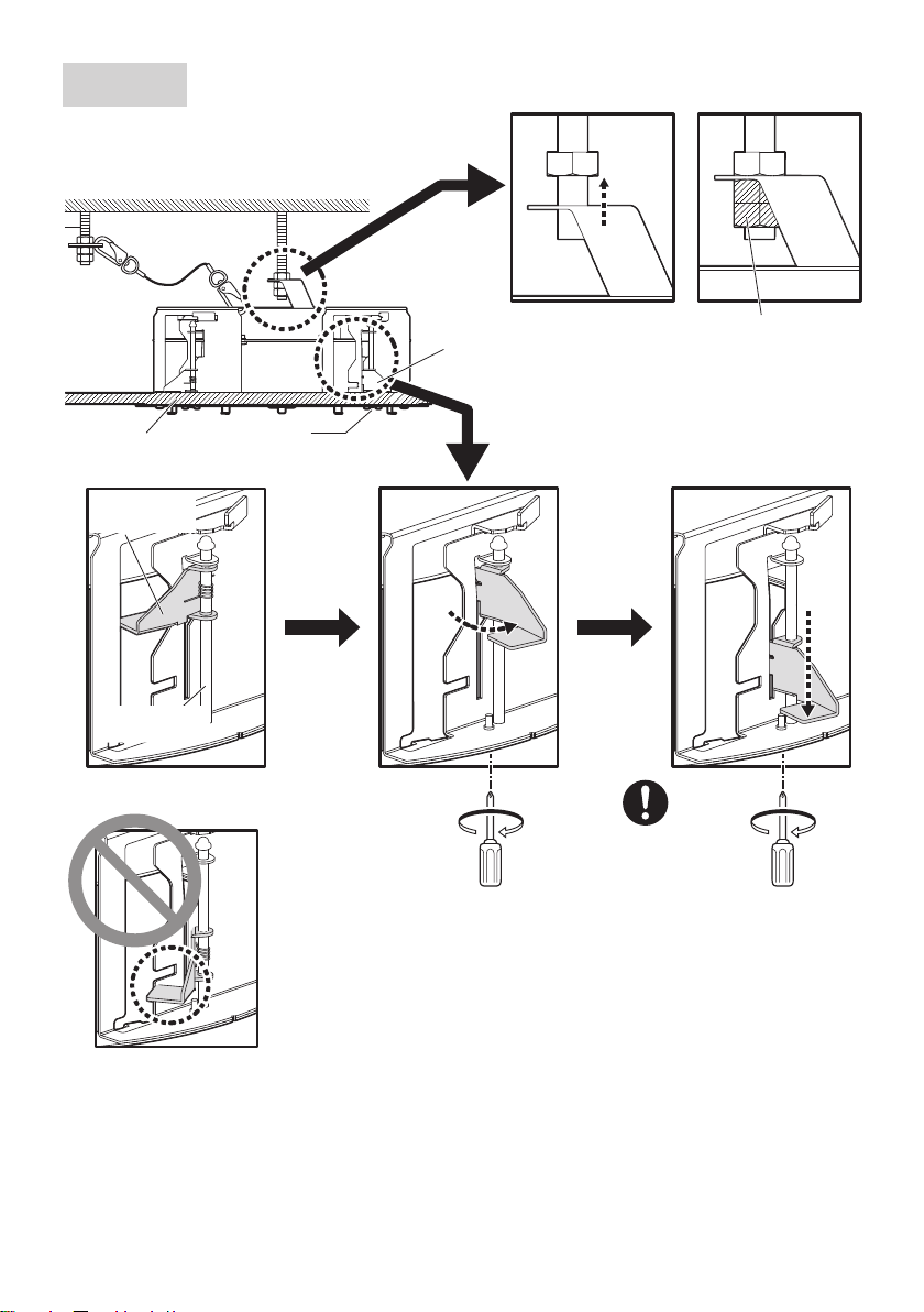
Precautions for installation
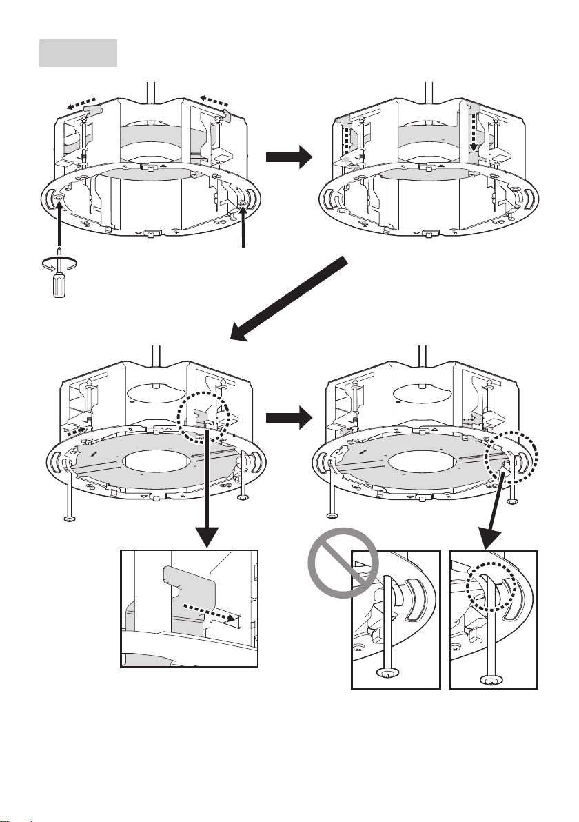
In order to prevent injury, the product must be securely mounted to the ceiling
according to the Installation Guide.
This product is designed to be used indoors.
This product is not operable outdoors. Do not expose this product to direct sunlight for hours
and do not install the product near a heater or an air conditioner. Otherwise, it may cause
deformation, discoloration and malfunction. Keep this product away from water and moisture.
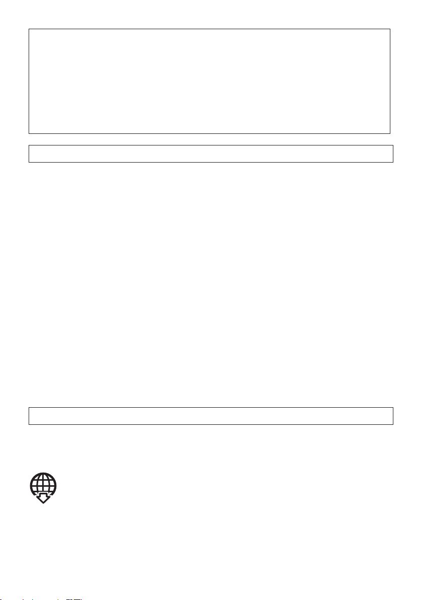
Installation area for this product
Make sure that the installation area is strong enough to hold
the total weight of the camera assembly before installation.
The installation area shall have 165 mm {6-1/2 inches} or
more space behind the ceiling.
The thickness of the ceiling board for installation can range
between 9mm {11/32inches} and 40mm {1-9/16inches}.
Make sure to remove this product if it will no
longer be used.
165mm
{6-1/2inches}
or more
Ceiling board: between
9mm {11/32inches} and
40mm {1-9/16inches}
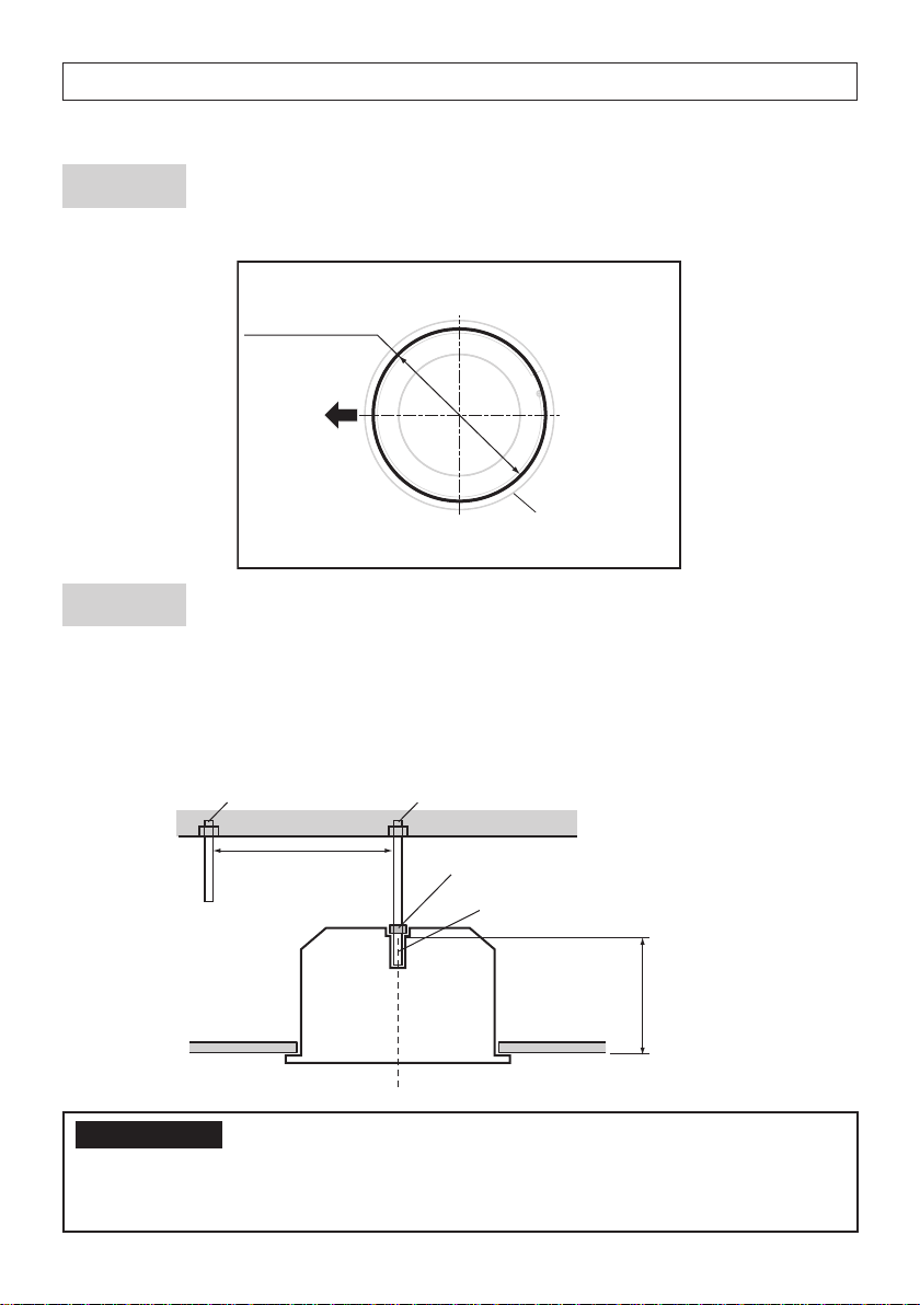
Standard Accessories
Safety wire* .......................................... 1 pc.
Safety wire angle*................................. 1 pc.
Fixing screw for attachment plate (M4 × 8 mm
{5/16 inches}) ........5 pcs. (of them, 1 for spare)
Template............................................... 1 pc.
Decorative cover................................... 1 pc.
* The product is shipped in a state where the safety wire is attached to the safety wire angle.
Other items that are needed (not included)
Anchor bolt (M10)*.............................. 2 pcs. Nut (M10) .......................................... 6 pcs.
* One anchor is used for securing the mounting chassis, and the other anchor is used for
connecting the safety wire. (See Step2)
IMPORTANT
• Prepare anchor bolts according to the material and strength of the area where the prod-
uct is to be installed. The pull-out strength of the anchor bolt shall be more than 5 times
of the total weight of the installed devices (including the camera body, ceiling mount
bracket, anchor bolts, and all other parts).

4
Installation
Refer to the operating instructions of the camera for details on the camera
installation (including the camera mounting, cable connection and adjustment).
Step 1
Create a ø300 mm {11-13/16 inches} hole.
Visual reference for
the decorative cover
Ceiling surface
ø300 mm
{11-13/16 inches}
Brand logo side
Step 2 Install two anchor bolts (M10: locally procured) into the ceiling.
①Determine the anchor bolt length (for securing the mounting chassis) by use of Template
(accessory).
②Position the nut (locally procured) by use of Template and mount the nut.
(The distance between the bottom surfaces of the ceiling board and nut shall be 136mm
{5-11/32 inches}.)
Anchor bolt
(for connecting the safety wire)
②Mount a nut
①Determine the anchor bolt length
Install the anchor bolt in the center of the hole
136mm {5-11/32 inches}
Template
Ceiling board
Anchor bolt
(for securing the mounting chassis)
1 m {3.28 feet} or less
IMPORTANT:
• When the existing anchor bolt is used as an anchor bolt for connecting the safety wire,
make sure that the distance between the anchor bolt and camera mounting position is
1m {3.28feet} or less.

5
Step 3 Secure the safety wire angle (accessory) to the anchor bolt (for
connecting the safety wire), and connect the safety wire
(accessory).
①Mount a nut so that the safety wire
angle is secured on the anchor bolt.
②Remove the safety wire from the safety
wire angle.
③Insert the groove of the portion ❶of
the safety wire angle into the anchor
bolt.
④Close the safety wire angle while
inserting the groove of the portion ❷of
the safety wire angle into the anchor
bolt.
⑤Connect the safety wire to the safety
wire angle again.
⑥Engage the nut from beneath, and
secure the safety wire angle with top
and bottom nuts.
⑦Engage another nut from beneath to
tighten and secure the nut that was
engaged from beneath in ⑥in a
double nut fashion.
<Image of safety wire connection>
Existing anchor bolt
Safety wire
Safety wire angle
Nut
(locally procured)
⑥⑦
①
Upper side
Lower side
Safety wire
③Insert
②Remove
④Close
❷
❶
⑤Connect
Safety wire angle
Anchor bolt
Note:
• When the existing anchor bolt
that has been installed is used
for connecting the safety wire,
the use of 2 spacer nuts is
helpful.
Spacer nuts
Spacer nuts
Safety wire angle
Existing anchor bolt
Safety wire

6
Step 4 Attach the safety wire.
Attach the safety wire to the mounting
chassis as shown in the illustration below.
Safety wire
(Accessory)
Ceiling board
Cables
Mounting
chassis
Fix the hook of the safety wire to this
product.
Roof space
Installation onward for the descriptions of the cable and the safety wire may be omitted.
Step 5 Check the orientation for inserting the mounting chassis into
the ceiling.
To align the i-PRO logo on the decorative cover, align the direction of the mounting chassis
before inserting the mounting chassis into the mounting hole on the ceiling board.
Mounting hole
Direction of
brand logo
Direction of
brand logo

7
Step 6 Secure the mounting chassis.
②
①
③
Recommended
tightening torque:
0.78 N·m {0.58 lbf·ft}
Ceiling board fixing bracket
(4 places)
Ceiling board
fixing screw
(4 places)
Double nuts
(locally procured)
Ceiling board
Ceiling board
fixing bracket
Ceiling board
fixing screw
Anchor bolt
(for securing the
mounting chassis)
When inserting the mounting
chassis

8
Step 7 Pull out the camera mounting stage
①Loosen the screws.
①①
②②
③
③
④
④

9
Step 8 Install the attachment plate
Camera mounting method
Fixing screw for
attachment plate (accessory)
Attachment plate
(camera accessory)
ARecommended tightening torque:
0.78 N·m {0.58 lbf·ft}
For Step 9, follow the installation procedure in the camera
installation section or the installation procedure leaflet.
Step 9
Bit (camera accessory)
Recommended tightening torque:
1.2 N·m {0.89 lbf·ft}

10
Step 10 Mount the decorative cover.
②
②
①
①
③
③
Recommended tightening torque:
0.4 N·m {0.3 lbf·ft}
I Mark
(4 places)
Decorative cover
fixing screw
Decorative cover
protrusions
(4 places)
Hook
(4 places)
②
②
①
③
①
• Recommended tightening torque:
0.78 N·m {0.58 lbf·ft}
• There are two places where the decorative
cover fixing screw can be fixed: the position
shown in the illustration and the opposite side.

11
取扱説明書 設置ガイド
工事説明付き
カメラ天井埋込金具
品番 WV-QEM506
このたびは、弊社製品をお買い上げいただき、まことにありがとうございます。
取扱説明書をよくお読みのうえ、正しく安全にお使いください。
ご使用前に「安全上のご注意」を必ずお読みください。
この取扱説明書は大切に保存してください。
製品の改良などにより、ご使用上影響のない範囲で、記載されている外観などが実際の
製品と異なる場合があります。
取扱説明書に記載されていない方法や、指定の部品を使用しない方法で施工されたこと
により事故や損害が生じたときには、当社では責任を負えません。また、その施工が原
因で故障が生じた場合は、製品保証の対象外となります。
i-PRO製品の「お問い合わせ」については、以下の弊社サポートウェブサイト
を参照してください。
https://i-pro.com/jp/ja/support_portal
※「日本エリア」でお使いの場合に限ります。日本以外でお使いの場合の
サービスはいたしかねます。
取扱説明書に記載されている「<管理番号:Cxxxx>」は、以下の弊社技術
情報ウェブサイト内で該当する情報を検索する際に使用する番号です。
https://i-pro.com/jp/ja/support_portal/technical_information
https://www.i-pro.com/

12
注意:
取扱説明書をよくお読みのうえ、正し
く安全にお使いください。
注記:
本金具は子供がいる可能性のある場所
での使用には適していません。
一般の人が容易に触れることができる
場所への設置はしないでください。
設置に必要なねじやそのほかの部材など
の情報については本書の該当部分を参照
してください。
安全上のご注意 必ずお守りください
人への危害、財産の損害を防止するため、必ずお守りいただくことを説明しています。
■ 誤った使い方をしたときに生じる危害や損害の程度を区分して、説明しています。
警告
「死亡や重傷を負うおそれ
がある内容」です。
注意
「軽傷を負うことや、財産の損害が
発生するおそれがある内容」です。
■ お守りいただく内容を次の図記号で説明しています。(次は図記号の例です)
してはいけない内容です。 実行しなければならない内容
です。
警告
■ 専用のカメラ以外は取り付けない
(落下によるけがや事故の原因となります。)
■ 工事は販売店に依頼する
(工事には技術と経験が必要です。火災、感電、けが、器物損壊の原因となります。)
⇒必ず販売店に依頼してください。
■ 落下防止対策を施す
(落下によるけがや事故の原因となります。)
⇒落下防止ワイヤーを必ず取り付けてください。
■ ねじやボルトは指定されたトルクで締め付ける
(落下によるけがや事故の原因となります。)
■ 設置の説明にしたがって天井に正しく、しっかり取り付ける
(けがや事故の原因となります。)
注意
■ 金属のエッジで手をこすらない
(強くこするとけがの原因となります。)
本金具をご使用の際は、取り付けるカメラの取扱説明書に記載された「安全上の
ご注意」とあわせてお読みください。

13
商品概要
本金具は、カメラ用の天井埋込金具です。二重天井で石こうボードなどのねじ引き抜き強
度が弱い場所に使用でき、カメラの露出部分を小さく見せるために埋込型になっています。
取り付け可能なカメラの最新情報
<管理番号:C0501>
仕様
使用温度範囲 −50℃〜+60℃
寸法 最 大 径:φ328mm/高 さ:153mm(飾りカバーの厚み17.5mmを含む)
質量 約2.0kg
仕上げ 本体 :処理鋼板
飾りカバー :ABS樹脂 i-PROホワイト <WV-QEM506-W>
ブラック <WV-QEM506-B>
設置上のお願い
■ 設置工事は電気設備技術基準に従って実施してください。
本金具の設置・接続を始める前に必要な周辺機器やケーブルを確認し、準備してください。
接続する前に、カメラ、PCなど接続する機器の電源を切ってください。
■ 傷害防止のため、本金具は、設置の説明に従って天井にしっかりと取り付ける
必要があります。
■ 本機は屋内専用です
屋外での使用はできません。長時間直射日光の当たるところや、冷・暖房機の近くには設
置しないでください。変形・変色または故障・誤動作の原因となります。また、水滴や水
沫のかからない状態で使用してください。
■ 本金具の取付場所について
設置場所は、カメラ取り付け時の総質量に十
分耐えられる強度を持っていることを確認し
てから取り付けてください。
天井裏が165mm以上ある場所に設置してく
ださい。
天井板 の厚さは、9mm〜40mmまで取 り
付けが可能です。 天井板9mm〜40mmまで
165mm以上
■ 本金具を使用しなくなった場合は放置せず、必ず撤去してください。

14
付属品をご確認ください
落下防止ワイヤー※................................. 1個
落下防止ワイヤーアングル※.................. 1個
アタッチメント金具固定ねじ(M4×8mm)
..................................5本(うち1本は予備)
型紙........................................................... 1枚
飾りカバー............................................... 1個
※落下防止ワイヤーは落下防止ワイヤーアングルに取り付けた状態で出荷されています。
付属品以外に必要なもの
アンカーボルト(M10)
※....................... 2本 ナット(M10)......................................... 6個
※1本のアンカーは取付シャーシの固定に、もう1本のアンカーは落下防止ワイヤーの接
続に使用します。(Step2参照)
重要
本金具を設置する場所の材質や強度に合わせてアンカーボルトを用意してください。ア
ンカーボルトの引き抜き強度は、設置する機器(カメラ本体、カメラ天井埋込金具、ア
ンカーボルト、その他すべての部品)の総重量の5倍以上を確保してください。

15
設置する
カメラの取り付け、ケーブルの接続、調整などの詳細はカメラの取扱説明書を参照してく
ださい。
Step1
φ300mmの穴をあけます。
飾りカバーイメージ
天井面
φ300mm
ロゴ方向
Step2 コンクリート天井にアンカーボルト(M10:現地調達)2本を打ち
込む
①型紙(付属品)でアンカーボルト
の長さ(取付シャーシ固定用)を
決めます。
②型紙を使って位置決めし、ナッ
ト(現地調達)を取り付けます。
(天井板の下面から136mmの
位置にナットの下面がくるよう
にします。)
重要
既存のアンカーボルトを落下防
止ワイヤーの接続に使用する場
合、アンカーボルトとカメラ取
り付け位置との距離が1m以下
であることを確認してください。
アンカーボルト
(落下防止ワイヤー接続用)
②ナットを取り付ける
①アンカーボルトの
長さを決める
中心に打ち込む
136mm
型紙
天井板
アンカーボルト
(取付シャーシ固定用)
1m以下

16
Step3 アンカーボルト(落下防止ワイヤー接続用)に落下防止ワイヤーアン
グル(付属品)を固定し、落下防止ワイヤー(付属品)を接続する
①アンカーボルトに落下防止ワイヤーア
ングルが固定されるようナットを取り
付けます。
②落下防止ワイヤーを落下防止ワイヤー
アングルから外します。
③落下防止ワイヤーアングルの❶側の
溝を、アンカーボルトに入れます。
④落下防止ワイヤーアングル❷側の溝
を、アンカーボルトに入れながら、落
下防止ワイヤーアングルを閉じます。
⑤落下防止ワイヤーを落下防止ワイヤー
アングルに取り付けます。
⑥ナットを下から通し、上 下のナットで落
下防止ワイヤーアングルを固定します。
⑦手順⑥で下から通したナットをダブル
ナットで締め付け、固定します。
既存のアンカ−ボルト
落下防止ワイヤー
落下防止
ワイヤーアングル
<落下防止ワイヤーの接続>
①
ナット
(現地調達)
⑥⑦
落下防止
ワイヤー
落下防止ワイヤー
アングル
アンカーボルト
②外す
③挿入
上側
④閉じる
下側
❶
⑤取り付ける
❷
メモ
既存のアンカーボルトを使用
して落下防止ワイヤーを接続
する場合、中間挿入式ナット
を2個使用すると便利です。
中間挿入式
ナット 中間挿入式ナット
落下防止ワイヤー
アングル
既存のアンカ−ボルト
落下防止
ワイヤー

17
Step4 落下防止ワイヤーを取り付ける
下図のように、落下防止ワイヤーを取付
シャーシに取り付けてください。
落下防止ワイヤー
(付属品)
天井板
各種ケーブル
取付
シャーシ
落下防止ワイヤーのフックを本金具に
固定する。
天井裏
以降のイラストでは、ケーブルや落下防止ワイヤーは省略されている場合があります。
Step5 取付シャーシを天井に挿入する向きを確認する
飾りカバーのi-PROロゴの位置と合わせるために、天井板に挿入する前に取付シャーシの向
きを合わせます。
取付口
ロゴの
方向
ロゴの
方向

18
Step6 取付シャーシを固定する
②①
③
推奨締付トルク:
0.78N·m{8kgf·cm}
天井押さえ金具
(4か所)
天井板固定ねじ
(4か所)
ダブルナット
(現地調達)
天井板
天井押さえ
金具
天井板
固定ねじ
アンカーボルト
(取付シャーシ固定用)
取付シャーシ挿入時

19
Step7 カメラ取付ステージを引き出す
①ねじを緩める
①①
②
②
③③
④
④

20
Step8 アタッチメント金具を取り付ける
■ カメラの取付方法
アタッチメント金具
固定ねじ(付属品)
アタッチメント金具
(カメラ付属品)
A
推奨締付トルク:
0.78N·m{8kgf·cm}
Step9はカメラの設置編、または設置手順チラシの
設置手順に従ってください
Step9
ビット(カメラ付属品)
推奨締付トルク:
1.2N·m{12.2kgf·cm}
Table of contents
Other i-PRO TV Mount manuals