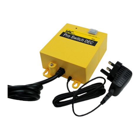
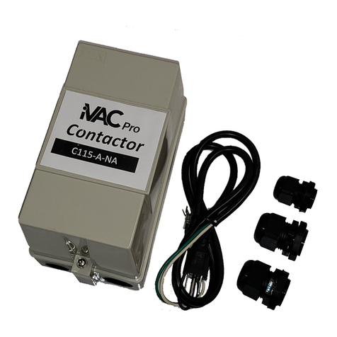
i-Vac iVAC Pro User manual

Tool HP
USER GUIDE
BCTINT Limited
WWW.IVACSWITCH.COM

Introduction
This User Guide covers the General Description,
Features
system.
collection dust a and tools power Power High between
interface an as Switch’ Pro ‘iVAC an conjunctionwith
in work to developed been has HP’ ‘Tool HP’).The (‘Tool
HP’ Tool Pro ‘iVAC the of Programming and
Table of Contents
1 Warnings
2 Physical Features
3 General Description
4 Set Up
5 Modes of Operation
6 Program Switch
7 System Address

8 Multi Tool Operation
9 Tool Address
10 Active Current Threshold
11 Active Current LED Indicator
12 ‘Tool HP’ fSpeci cations
13 Regulatory Compliance
14 Warranty
15 Contact
1 Warnings
Please read the operating instructions before use. The
‘Tool HP’ is intended for indoor use in dry locations only.
The ‘Tool HP’ is powered from an AC to AC Adaptor. The
‘Tool HP’ should only be powered by the adaptor supplied
with the unit. Other adaptors may cause damage.

2 Physical Features
Figure 1
Figure 2 Figure 3
AC
Power
Jack
AC to
AC
Adaptor
Mode
Switch
Clip on
Current
Transformer
Active
Current
LED
Active
Current
Adjust
Program
Switch
Clip the
Clip On
Current
Transformer
around one
current
carrying
power lead
Current
Transformer
Jack Tool HP
Module

3 General Description
The ‘Tool HP’ has been designed to enable high powered
tools to be interfaced into the ‘iVAC Pro System’.
High power tools are those power tools that have high start up
surge currents or require more than 20Amps operating
current. It also includes power tools that operate at voltages
above 230Vac or are wired for three phase operation.
There are three main items to the ‘Tool HP’.
‘Tool HP’ module.
Clip On Current Transformer and cable.
AC Adaptor. 115Vac to 23Vac 0.2A UL/CSA Approved
In order to detect when a power tool is in operation the Clip
On Current Transformer is clipped onto one of the current
carrying power leads to the power tool. There is no electrical
connection; it is purely a magnetic pick up. This may require
access to a distribution box. (As shown in Fig. 3)
When the power tool is turned on or off, the ‘Tool HP’ will
transmit an On or Off signal to the ‘iVAC Pro Switch’, which
in turn controls a dust collector.
Active Current threshold; this is the level of current to the
power tool that will cause the ‘Tool HP’ to identify that the
power tool is active. This threshold is adjustable from 0.5
Amps to 3.5 Amps.

4 Set Up
The ‘Tool HP’ is powered from a 115Vac AC Adaptor. The
output from the adaptor plugs into the power jack on the
top surface of the ‘Tool HP’.
The Clip On Current Transformer should be clipped
around ONE of the current carrying conductors that
powers the power tool. (Live or Neutral but not Ground).
Care should be taken to ensure that there is no dirt or
foreign material on the two polished surfaces of the Clip
On Current Transformer as it is closed. The clip should be
fully closed and then latched.
The plug from the Clip On Current Transformer plugs into
the Current Transformer jack of the ‘Tool HP’.

5 Modes of Operation
The ‘Tool HP’ has three modes of operation;
Auto – Off
As
off. turn to it instructing Switch’ Pro ‘iVAC the
to sent is transmission a Off to On from transferred
is switch Mode the As on. turn to it instructing
Switch’ Pro ‘iVAC the to sent is transmission
a ON to OFF from transferred is Switch Mode the
collector. dust the controls
turn in which off, or on turned is tool power connected
the time each Switch’ Pro ‘iVAC the to information
wireless transmits HP’ ‘Tool the Mode Auto
the In Switch. Mode the by set as ON –
6 Program Switch
The Program Switch is accessed through the Program
Address.
Tool the and Address System the of programming the
enables It unit. the of base the in located cover Switch

7 System Address
A System consists of an ‘iVAC Pro Switch’ and up to eight
‘iVAC Pro Tools’ that are intended to work together.
By means of the Program Switch, the ‘iVAC Pro Tool’ can
be assigned to work on one of four System Addresses,
A, B, C or D. The System Address is to enable up to
four systems to operate independently while within
communication range of each other.
System
Address S1 S2
A Off Off
BOnOff
C Off On
DOnOn
System Address Programming.
All switches shown in Off position.

8 Multi Tool Operation
The ‘iVAC Pro’ system has been designed so that up
to eight
Switch’. Pro ‘iVAC the off turn will
off, turn to tool last The Switch’. Pro ‘iVAC the on turn
will on, turn to Tool’ Pro ‘iVAC first The time. same
the at operation in be can Tools’ Pro ‘iVAC Several
Address. System same the on Switch’ Pro ‘iVAC
one with communicate can Tools’ Pro ‘iVAC

9 Tool Address
Each ‘iVAC Pro Tool’ must be assigned an independent
one of eight tool address. This information is presently
used by the ‘iVAC Pro Switch’ to enable it to know the
status of each individual tool in a system. The Tool
Address is set by means of the Program Switch
Tool Address Programming.
All switches shown in Off position.
Tool Address S4 S5 S6
1 On Off Off
2 Off On Off
3OnOnOff
4 Off Off On
5OnOffOn
6 Off On On
7OnOnOn
8 Off Off Off

10 Active Current Threshold
Active Current is that current at which the ‘Tool HP’
identifies that the power tool has been turned on. The
Active Current can be set by means of an adjustment
between 0.5Amps to 3.5 Amps
In some power tools there is a standing current to power
such items as an on board computer. A rear panel
adjustment on the ‘Tool HP’ allows the Active Current
Threshold to be set above that of the standing current.
Access to a sensitivity adjustment is available through the
base of the unit.
11 Active Current LED Indicator
An LED indicator identifies when an active current is being
detected.
This indicator is for use in the Auto Mode only.
Set Mode Switch to Auto. With the power tool not
operating, set the adjustment fully counter clockwise and
then adjust clockwise until the LED indicator just turns off.
Note, the LED may already be off in the fully counter
clockwise position.
When the power tool is turned on the LED should turn on.

12 ‘iVAC Pro Tool HP’ Specifications
Plastic housing
Powered
Current
Ambient
Active
One Addresses Tool Eight of
Addresses System Four of One 3.5A
to 0.5A from adjustable Threshold Current
features. settable
User 30C – 0 temperature, operating
feet. forty Range transformer.
Current On Clip of means by detect
approved. CSA UL/
adaptor. 0.2A 23Vac to Vac 115 a from
plastic 94V0 ABS 2” x 5” x 5”
13 Regulatory Compliance
This device complies with part 15 of the FCC rules.
Operation is subject to the following two conditions:
(1) This device may not cause harmful interference, and (2)
this device must accept any interference received,
including interference that may cause undesired
operation.
Any changes or modifi cations of this product, not approved by
the manufacturer will void the user’s authority
to operate the equipment.
Contains FCC YCH-ID: IVACRFM 8940A-IC: IVACRFM

14 Warranty
The ‘iVAC Pro Tool HP’ is warranted to the original consumer
purchaser for a period of one year from the date of purchase,
against defects in materials or workmanship. Proof of purchase
is
abused,
This
the America. of States United or Canada in purchased units
HP’ Tool Pro ‘iVAC to applies only warranty This HP’. Tool Pro
‘iVAC the of use or purchase the with connection in incurred
costs other any or charges labor damages, consequential
damages, incidental for Limited BCTINT of part the on liability
any exclude, to intended is and cover, not does warranty
company. the by determined as damaged, or altered
misused, been not has product the that provided option; its
at credit, or replacement repair, of consist shall warranty this
under obligation Limited BCTINT Company, The required.
15 Contact
120
1-613-599-8988 1-800-775-5579
Customer Service Toll Free :
WWW.IVACSWITCH.COM email:
Canada 1E9 K2S ON Stittsville, 108 Unit Road, Iber
LimitedBCTINT
210556-0 00

Tool HP
USER
GUIDE
UTILISATEUR
DE
GUIDE
BCTINT Limited
WWW.IVACSWITCH.COM

Introduction
Ce
et
poussière. de collecte de système un et puissance grande
de outils les entre interface une comme Pro IVAC Switch
un avec conjonction en fonctionner pour conçu été a HP Tool
Le HP’). (‘Tool ’HP Tool Pro iVAC du programmation la
Caractéristiques
Générale, Description la couvre l'utilisateur de guide
Table
1
2
3
4
5
6
7
8
9
10
11
12
13
14
15 Contact
Garantie
réglementaire Conformité
HP Tool de spécifications Les
Actif courant du LED Indicateur
Actif courant de Limite
Outil Adresse
Tool Multi Fonctionnement
Système Adresse
programme Interrupteur
fonctionnement de modes
initiale Configuration
générale Description
physiques Caractéristiques
Avertissements
matières des

1
S'il
Le
dommages. des
causer peuvent adaptateurs D'autres l'unité. avec fourni
l'adaptateur par que alimenté être doit neHP ToolLe
CA. à CA adapteur un par alimenté est HP Tool
seulement. secs endroits desdans l’intérieur à
utilisé être pour conçu est HP Tool Le l'utilisation. avant
fonctionnement de instructions les lire plaît vous
Avertissements

2 Caractéristiques physiques
Figure 1
Figure 2 Figure 3
Prise
CA
courant
de
Adaptateur
CAàCA
Sélecteur
mode
de
Clip
transformateur
decourantsur
Témoin
LED-actif
courant
de
Ajustement
actif
courantde
Interrupteur
programme
de
Fixez
clip
transformateur
autour
de tension
fildes
d`une
courantde
sur
le
Prise
courantde
transformateur
de
Module
HPTool

3
Le
pour
Outils
jusqu'à
courant.
Il
Module Clip
Adaptateur
Afin
Lorsque
Seuil
Ampères
ampères.
3,5 à 0,5 de réglable est seuil Ce actif. est
l’outil que indiquer pour HP l'Tool provoquer va qui l'outil
à courant de niveau le est qui ce actif, courant de
poussière.
de collecteur un commande tour, son à qui Pro, IVAC
l’interrupteur à Arrêt ou Marche de signal un transmettra
HP Tool le tension, hors ou tension sous est l'outil
3) Fig. la montre le (Comme distribution. de boîte
une à l’accès nécessiter peut Cela magnétique. opération
une purement est elle électrique, connexion de pas a
n'y Il électrique. l'outil aliment qui câbles des un sur clipsé
est courant de transformateur sur clip le fonctionnement
en est électroportatif outil un quand détecter de
CSA / UL Approuvé 0.2A 23Vca à 115Vca CA.
câble.
le et courant de transformateur sur HP Tool
HP. Tool le pour principaux éléments trois ya
phase. trois de opérations des pour câblés sont
ou CA 230V de au-dessus tensions des à fonctionnent
qui électriques outils des également comprend Il
d'exploitation ampères 20 de plus d'exiger
ou choc de courants des élevé démarrage de
ont qui électriques outils les sont puissance haute de
Pro. IVAC système le dans interfacé être puissance
haute à outils les permettre pour conçu été a HP Tool
générale Description

4
Le
sortie
surface
Le
autour
alimente
Des
une
La
Le HP. Tool du courant de transformateur
sur branche se courant de transformateur clip du prise
alors. verrouillée
et fermée complètement être devrait clip Le fermé.
est qu'il tel courant de transformateur clip du polies surfaces
deux les sur étrangère substance ni poussière de pas
ait n'y qu'il assurer pour prises être doivent précautions
sol). au non mais neutre ou (vivent électrique. l'outil
qui courant de porteurs conducteurs des l'un de
coupés être doivent courant de transformateur Clip
HP. Tool du supérieure la sur
d'alimentation prise la sur branche se l'adaptateur de
La 115Vca. adaptateur un par alimenté est HP Tool
Configurez

5
Le
-
Tool
chaque
Comme
transmission
il
une
s'éteindre de demandant lui Switch Prol’IVAC
a envoyée est transmission Off à Onde
transféré est mode de commutateur le Quand s'allume.
" Switch Pro 'IVAC l'instruction à envoyé est
une ON à OFF de transféré est mode de commutateur le
poussière. de collecteurle
tour son à commande qui ce tension, hors ou allumé
est raccordé électrique l'outil que fois Pro l’iVAC
de l’interrupteur a fil sans informations des transmet HP
le automatique, modeEn
mode. de sélecteur le par défini que tel ON OFF -AUTO
fonctionnement: de modes trois de dispose HP Tool
fonctionnement de modes
6
Le
l’outil. de l'adresse et système du l'adresse de programmation
la permet il l’unité. de base la à situé commutateur du
couvercle le sous accessible est programme de commutateur
programme Interrupteur
Other manuals for iVAC Pro
3
Table of contents
Other i-Vac Controllers manuals