manuals.online logo
Brands
  1. Home
  2. •
  3. Brands
  4. •
  5. IAME
  6. •
  7. Engine
  8. •
  9. IAME 125cc LEOPARD TaG Installation instructions

IAME 125cc LEOPARD TaG Installation instructions

ZZZHXURNDUWGH
MAN-016 D
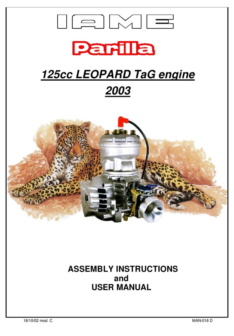
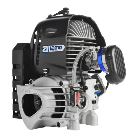
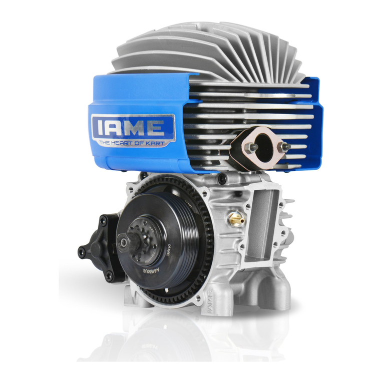
125cc LEOPARD TaG engine
2003
ASSEMBLY INSTRUCTIONS
and
USER MANUAL
18/10/02 mod. C
ZZZHXURNDUWGH
ZZZHXURNDUWGH
18/10/02 mod. C MAN-016 D
1
INDEX
GENERAL DESCRIPTION OF THE "LEOPARD" ENGINE
CHARACTERISTICS OF THE "LEOPARD" ENGINE – OPERATIONAL LIMITS
1- Content of the packing
2- Motor identification Number
3- Preparation and in tallation of the engine on the cha i
3.1 In tall the water cooling y tem
3.2 Exhau t header a embly
3.3 Preparation and in tallation of the motor-mount
3.4 In tall the carburetor
3.5 In tall the engine on the cha i
3.6 In tall the clutch cover with H.T. coil
3.7 In tallation and connection of the power pack box
3.8 Electrical connection on the engine
3.9 In tallation of the intake ilencer
3.10 In tall the exhau t
4- GASOLINE and OIL
5- Carburetor Adju tment guide
6- Starting and topping the engine
7- Engine break-in
8- Inlet ilencer
9- Exhau t y tem
10- Centrifugal clutch
11- In truction for the a embly/di a embly of the clutch
12- Battery
13- Spark plug and thermal degree
14- Choice of the be t procket ratio
15- Scheduled maintenance
16- Trouble hooting
17- Engine and acce orie pre ervation
Attachment : - Fa tener Torque Table
- Wiring diagram
Page
1
2
3
4
5
5
9
9
10
12
13
14
15
18
19
20
21
22
22
22
23
23
25
26
27
28
31
32
33
34
35
ZZZHXURNDUWGH
ZZZHXURNDUWGH
18/10/02 mod. C MAN-016 D
1
GENERAL DESCRIPTION OF THE "LEOPARD" ENGINE
This engine of the "TaG" series (To ch and Go) has been expressly designed and
developed for the powering of karts for hobby racing on closed tracks, destined for this
specific p rpose. When designing this new line of engines, the technical sol tions already
adopted for the high performance engines were sed, in order to g arantee the highest
reliability of components, when the operating limitations are respected.
The motor is a single cylinder sing the two stroke principle.
The cylinder and the crankcase are in al mini m alloy.
The pressed in liner is made of centrif gated cast iron, f lly machined to g arantee the
best possible stability.
The head is separated from the cylinder and sec red by st ds.
The crankshaft is b ilt and s pported by two ball-bearings. The crankshaft is of steel alloy,
hardened and tempered , as is the connecting rod which r ns on roller bearings.
The igniton incl des a 4 pole stator/rotor with integral pick- p, an H.T. coil and an
electronic nit with micro-processor (Power-Pack), complete with wiring harness.
The main feat res of the ignition are:
- D ring the start of the engine, the power-pack activates a booster which increases the
spark energy to facilitate the starting of the engine.
- The ignition system permits, thro gh the electronic nit, the onboard battery recharging
d ring the normal se of the engine.
- The spark is generated also witho t a battery: it is therefore possible, in case of
emergency, to start the engine with an external starter nit.
The engine has an integrated electric starter; by p shing the green start b tton the starter
activates a bendix type gear which engages the starter ring assembled on the cl tch.
The engine is provided with an a tomatic dry centrif gal cl tch with low maintenance and
with interchangeable sprocket.
The carb retor is a diaphragm Tillotson carb retor with integral f el p mp, filter and all
position mo nting capability.
The battery (12 V- 7.2Ah) is a sealed, no maintenance battery and is s pplied already
preassembled in the Power Pack s pport box which can be easily adapted to all existing
chassis.
The exha st, incl ded in the s pply, is already t ned for the best possible performance.
The engine is s pplied with a kit which incl des the radiator, the p mp, water hoses and
whatever necessary for the assembly on the kart.
ZZZHXURNDUWGH
ZZZHXURNDUWGH
18/10/02 mod. C MAN-016 D
2
CHARACTERISTICS OF THE "LEOPARD" ENGINE - OPERATIONAL LIMITS
1. The characteristics of the engine are the following :
• Cycle: OTTO / 2 stroke
• Original c bic capacity: 123.7 cc
• Original bore: 54.00 mm
• Max. theoretical bore: 54.28 mm
• Stroke: 54.00 mm
• L brication : F el-Oil mix
• Ind ction: Reed valve
• Carb retor: Membrane , Tillotson
• Cooling : water
• Ignition: Digital / 4 poles with internal rotor
• Battery charge: With integral generator
• Electric start: 12V/0.30 Kw
• Cl tch: A tomatic, dry, centrif gal
2. OPERATIONAL LIMITS:
• Max. RPM : 15000 RPM
• Min. waterTemperature: 45°c
• Max. water Temperature: 90°c
ATTENTION:
Never exceed the ab ve limits, n bligati n f IAME exists in case the ab ve
limits are exceeded.
ZZZHXURNDUWGH
ZZZHXURNDUWGH
18/10/02 mod. C MAN-016 D
3
1- CONTENT OF THE PACKING
Each Leopard engine is delivered with the nder shown accessories:
-125 cc LEOPARD-
TaG engine
EXHAUST
• Flexible 1
• Spring For Flexible 3
• Exhaust Fiber Strip 1
• Exhaut Header 1
• Exhaust Muffler 1
INDUCTION
• Tillotson Carburetor 1
• Intake Silencer 1
• Intake Silencer Support 1
• Accelerator Cable racket 1
ELECTRICAL
• attery 12 V 1
• attery Support 1
• attery Strap 1
• attery Clamps 2
• Power Pack ox with Harness 1
• Plastic Fixing Clamps 8
• NGK R 10 EG Spark Plug 1
• Spark Plug Cap 1
MISCELLANEOUS
• Additional Engine Plate 1
• Water proof cover 1
• Clutch cover with H.T. coil 1
WATER COOLING
• Radiator 1
• Radiator Support Kit 1
• Complete Hose Kit 1
• Pump, complete 1
ZZZHXURNDUWGH
ZZZHXURNDUWGH
18/10/02 mod. C MAN-016 D
4
2- MOTOR IDENTIFICATION NUMBER
The official motor identification n mber can be fo nd stamped in the lower left part of
the crankcase, next to the electric starter (see fig.) The n mber normally incl des a
letter followed by 4 digits (there can be exceptions in some special cases). Other
n mbers stamped on the crankcase or other s rfaces of the motor refer to vario s
man fact ring processes and do not identify the motor.
NOTE:
In case f need f r spares and when c ntacting the IAME Supp rt Centers,
please always refer t the M t r Identificati n Number and t the m t r m del.
ZZZHXURNDUWGH
ZZZHXURNDUWGH
18/10/02 mod. C MAN-016 D
5
3- PREPARATION AND INSTALLATION OF THE ENGINE ON THE CHASSIS
NOTE:
In case the engine is supplied already assembled n the chassis, it is at care f the assembler t
f ll w these instructi ns. The final cust mer, in this case, can skip this secti n and can start
reading fr m secti n 4.
Whenever the engine r a c mp nent is disassembled, it is necessary t always f ll w the under
sh wn instructi ns f r pr per reassembly.
3.1- INSTALL THE WATER COOLING SYSTEM
NOTE:
T install the water pump belts it is necessary t rem ve the rear axle.
1
REINSTALL THE REAR AXLE AFTER
HAVING INSERTED THE TWO BELTS.
SUGGESTION:
INSTALL OTHER TWO BELTS AS SPARES
AND FIX THEM WITH TAPE TO THE AXLE.
2
INSTALL THE WATER PUMP (1 SCREW M6 X
45 WITH WASHER AND SELF LOCKING
NUT) ON THE PUMP BRACKET ON THE
REAR CROSS RAIL (SEE FIG. 1).
IN CASE THERE IS NO BRACKET FOR THIS
PURPOSE IT I S NECESSARY TO INSTALL
THE PUMP ON REMOVABLE CLAMPS
AVAILABLE IN DIFFERENT DIAMETERS (∅
28/30/32mm) AS ACCESSORIES (SEE FIG.
2).
TIGHTEN BY HAND THE SCREW ON THE
PUMP LETTING IT FREE TO ROTATE FOR
THE TENSIONING OF THE BELTS.
3
INSTALL ON THE AXLE THE DRIVING
PULLEY (n°2 CLAMPS AVAILABLE IN
DIFFERENT DIAMETERS ∅ 30/35/40/50mm)
ALIGNING ITS RACES WITH THE DRIVEN
PULLEY.
TIGHTEN THE CLAMPS WITH TWO SCREWS
M6 X 25.
Fig.1
Fig.2
Fi
g
.3
ZZZHXURNDUWGH
ZZZHXURNDUWGH
18/10/02 mod. C MAN-016 D
6
4
INSTALL THE BELTS AND TENSION (SEE
FIG. 4).
BEFORE INSTALLING THE RADIATOR PREASSEMBLE THE FOLLOWING COMPONENTS
5
INSERT THE RUBBER DAMPENERS INTO
THE FIXING HOLES OF THE RADIATOR AND
INSERT THE SPACERS (SEE FIG. 5).
6
INSERT THE BUSHES INTO THE RADIATOR
SUPPORT BRACKET.
PLACE THE BRACKET BETWEEN THE
RADIATOR FIXINGS (SEE FIG. 6).
Fi
g
.4
Fig.5
RUBBER DAMPENER
SPACER
BUSH
RADIATOR SUPPORT
BRACKET
Fig.6
ZZZHXURNDUWGH
ZZZHXURNDUWGH
18/10/02 mod. C MAN-016 D
7
7
FIX THE SUPPORT BRACKET TO THE
RADIATOR, AND ALSO INSERT THE UPPER
SUPPORT BRACKET (SCREWS M6X90 AND
M6X85 WITH NUTS).
PLACE THE RADIATOR LOWER FIXING
CLAMP AND THE SPACER ON THE
RADIATOR SUPPORT BRACKET (SCREW
M8X45 WITH NUT) (SEE FIG. 7).
8
PLACE THE LOWER FIXING CLAMP ON THE
CHASSIS SIDE RAIL (BRAKE SIDE) (N°2
SCREWS M8X45 WITH NUTS) TIGHTEN THE
BOLTS BY HAND (SEE FIG. 8).
9
PLACE THE RADIATOR SO THAT THE HOLE,
ON THE UPPER RADIATOR BRACKET, AND
ONE OF THE UPPER HOLES ON THE
BEARING SUPPORT BOX, MATCH (SEE
FIG. 9).
ONCE YOU FIND THE CORRECT POSITION,
TIGHTEN ALL THE BOLTS
10
THE KIT INCLUDES THREE RUBBER
HOSES.
CONNECT THE FIRST HOSE TO THE
FITTING ON THE RADIATOR INLET AND THE
FITTING ON THE ENGINE OUTLET, TIGHTEN
WITH STEEL CLAMPS (SEE FIG.10).
Fi
g
.7
UPPER SUPPORT BRACKET
RADIATOR LOWER FIXING CLAMP
SPACER
Fig.8
Fi
g
.9
SCREW M6X90
SCREW M6X85
ZZZHXURNDUWGH
ZZZHXURNDUWGH
18/10/02 mod. C MAN-016 D
8
11
CONNECT THE SECOND HOSE BETWEEN
THE FITTINGS ON THE RADIATOR OUTLET
AND THE PUMP INLET.
CONNECT THE THIRD HOSE BETWEEN
THE FITTINGS ON THE PUMP OUTLET AND
THE ENGINE INLET (SEE FIG. 10).
TIGHTEN WITH STEEL CLAMPS.
BEFORE STARTING THE ENGINE FOLLOW THESE RECOMMENDATIONS:
• Unscrew the cap on the radiator and loosen the breather pl g on the engine head.
• Fill the radiator ntil the water comes o t from the pl g on the head (there is no air in
the system now) and the radiator is completely filled. Tighten the cap (the system
contains appr. 1 lt. of water).
• It i advi able to put a mall cup to recover water from the breather on the cap in
ca e of boiling water.
• After the engine run-in, check the water level in the radiator and top up if
nece ary.
Fi
g
.10
ZZZHXURNDUWGH
ZZZHXURNDUWGH
18/10/02 mod. C MAN-016 D
9
3.2
EXHAUST HEADER ASSEMBLY
NOTE:
THE ENGINE IS SUPPLIED WITH THE
EXHAUST GASKET AND NUTS ALREADY
INSERTED. WHEN THE SHIPMENT IS MADE
AN EXHAUST COVER TO PROTECT THE
INTERNAL PARTS.
3.2.1 REMOVE THE NUTS AND THE EXHAUST
COVER.
3.2.2 MAKE SURE THE EXHAUST GASKET IS
SEATED AND INSTALL THE EXHAUST
HEADER (SEE FIG 1).
3.2.3 INSTALL THE WASHERS
SUGGESTION:
PUT THE ENGINE IN HORIZONTAL POSITION
AND SET INTO POSITION THE WASHERS
WITH A SCREWDRIVER.
3.2.4 INSTALL THE THREE NUTS.
TORQUE AT 9 ÷ 11 Nm (80 ÷ 100 in-lb)
10 mm SOCKET WRENCH (OR 10 mm OPEN WRENCH.)
PREPARATION AND INSTALLATION OF THE MOTOR MOUNT
NOTE: ALL DIMENSIONS ARE IN MILLIMETERS
3.3
3.3.1 DRILL 4 HOLES (DIAM. 8.5mm) IN THE MOTOR MOUNT.
Fi
g
.1
ZZZHXURNDUWGH
ZZZHXURNDUWGH
18/10/02 mod. C MAN-016 D
10
3.3.2 BEFORE INSTALLING THE MOTOR
MOUNT, POSITION THE ADDITIONAL MOUNT
PLATE ON THE CRANKCASE (SEE FIG. 2).
3.3.3 INSTALL THE MOTOR MOUNT. MAKE
SURE TO USE M8 ALLEN SCREWS WITH A
LENGHT SUCH AS TO ENGAGE, IN THE
CRANKCASE, A THREADED PORTION
LENGHT OF 16÷19mm (THE SCREW MUST
PROTRUDE FROM THE PLATE FOR 16÷19mm)
(SEE FIG. 3 AND DRAW. PAG. 9)
4 ALLEN SCREWS M8 – TORQUE AT 22÷24
Nm (190 ÷ 210 in-lb)
6 mm ALLEN WRENCH.
INSTALL THE CARBURETOR
3.4
3.4.1 INSTALL THE GAS CABLE CLAMP ON
THE SUPPORT (SEE FIG. 4)
12 POINT WRENCH 10mm
Fi
g
.4
Fi
g
.2
Fi
g
.3
ZZZHXURNDUWGH
ZZZHXURNDUWGH
18/10/02 mod. C MAN-016 D
11
3.4.2 REMOVE 2 SCREWS 3.5mm ON THE
CARB. PUMP (IN CORRESPONDENCE OF THE
THROTTLE LEVER) (SEE FIG. 5).
SCREWDRIVER 4.8 mm.
3.4.3 INSERT THE GAS BRACKET AND THE
TWO SCREWS (SEE FIG. 6).
3.4.4 INSTALL THE INTAKE SUPPORT – 2
SCREWS M5 X10 (SEE FIG. 7)
3 mm ALLEN WRENCH
3.4.5 INSTALL THE CARBURETOR
(SEE FIG. 8 / 9).
!" REMOVE THE TWO M6 NUTS FROM THE
INLET MANIFOLD.
!" REMOVE THE PLASTIC PLUG FROM THE
INLET MANIFOLD.
ATTENTION:
MAKE SURE THAT THE PRESSURE HOLE ON
THE GASKET IS NOT PLUGGED.
10MM OPEN WRENCH
Fi
g
.5
Fi
g
.6
Fi
g
.7
Fi
g
.8
ZZZHXURNDUWGH
ZZZHXURNDUWGH
18/10/02 mod. C MAN-016 D
12
ATTENTION:
WHEN REPLACING THE CARB GASKET
ALWAYS MAKE SURE THAT THE GASKET IS
INSTALLED SO THAT THE HOLE IN THE
GASKET MATCHES WITH THE TWO
PRESSURE HOLES IN THE CARB. AND IN
THE CRANKCASE: OTHERWISE THE ENGINE
WON’T START.
INSTALL THE CARBURETOR.
N.2 NUTS M6 AND TWO WASHERS.
TORQUE AT 6 ÷ 10 Nm (50 ÷ 90 in-lb)
3.5 INSTALL THE ENGINE ON THE
CHASSIS
3.5.1 POSITION THE ENGINE ON THE 2
OUTSIDE MAIN RAILS AND FIX THE MOTOR-
MOUNT WITH THE TWO CLAMPS (SEE
FIG.10)
SUGGESTION:
NEVER TORQUE COMPLETELY THE CLAMPS
UNTIL THE CHAIN IS INSTALLED AND
PROPERLY ALIGNED.
3.5.2 CHECK THE ALIGNMENT OF THE
ENGINE SPROCKET AND THE AXLE
SPROCKET WITH A STRAIGHT EDGE (SEE
FIG. 11).
3.5.3 INSTALL THE CHAIN (PITCH: # 219) (SEE
FIG. 12).
Fi
g
.9
Fi
g
.11
Fi
g
.10
Fi
g
.12
ZZZHXURNDUWGH
ZZZHXURNDUWGH
18/10/02 mod. C MAN-016 D
13
3.5.4 MOVE THE ENGINE ON THE RAILS AND
OPTIMIZE THE CHAIN TENSION .
ATTENTION:
THE PLAY OF THE CHAIN MUST BE APPR.
15mm (½÷¾ inch) MEASURED IN THE SHOWN
POINT (SEE FIG. 13)
3.5.5 TORQUE THE CLAMP SCREWS
INSTALL THE CLUTCH COVER WITH
H.T. COIL
3.6
3.6.1 REMOVE THE 3 SCREWS M6 X 30 ON
THE CRANKCASE (SEE FIG. 14) AND INSTALL
THE CLUTCH COVER WITH H.T. COIL (SEE
FIG.15).
TORQUE THE 3 SCREWS AT 8 ÷ 10 Nm
(70 ÷ 90 in-lb)
ATTENTION:
ALWAYS MAKE SURE THAT THE GROUND
CABLE ALWAYS CONNECTS THE COIL WITH
THE ENGINE. AN INADEQUATE GROUNDING
COULD DAMAGE THE IGNITION BEYOND
REPAIR.
THE POSITION OF THE H.T. COIL HAS BEEN
CHOSEN TO BE AS FAR AS POSSIBLE FROM
THE EXHAUST AS THE EXCESSIVE HEAT
COULD DAMAGE THE COIL BEYOND REPAIR.
5mm ALLEN
Fi
g
.15
Fig.13
15mm
Fi
g
.14
ZZZHXURNDUWGH
ZZZHXURNDUWGH
18/10/02 mod. C MAN-016 D
14
ELECTRICAL CONNECTION
(refer to the attached electrical chematic)
3.7
INSTALLATION AND CONNECTION
OF THE POWER PACK BOX.
NOTE:
THE POWER PACK BOX IS SUPPLIED
ALREADY ASSEMBLED ON THE BATTERY
SUPPORT (WITH BATTERY) . FOR A
CORRECT INSTALLATION FOLLOW THE
UNDER SHOWN INSTRUCTIONS.
3.7.1 EXTRACT THE BATTERY FROM THE
SUPPORT AFTER HAVING UNLACED THE
BATTERY STRAP (SEE FIG. 16).
3.7.2 POSITION THE SUPPORT CLAMPS ON
THE OUTSIDE RAIL (BRAKE SIDE) AT THE
HEIGHT OF THE SEAT.
NOTE:
DIFFERENT CLAMPS ARE AVAILABLE
DEPENDING ON THE DIAMETER OF THE
TUBE ON THE CHASSIS.
FIX THE CLAMPS BY HAND WITH 2
SCREWS M6 X 25 (SEE FIG. 17).
3.7.3 POSITION THE BATTERY SUPPORT
BOX ON THE CLAMPS MATCHING THE
ATTACHMENT HOLES (SEE FIG. 18).
FIX THE BOX WITH TWO SCREWS M6 X 10.
MOVE THE BOX WITH THE 2 CLAMPS TO
THE MOST SUITABLE POSITION.
TORQUE THE M6 SCREWS AT 8 ÷ 10 Nm
(70 ÷ 90 in-lb)
TWELVE POINT WRENCH 10mm
Fi
g
.16
Fi
g
.17
Fi
g
.18
ZZZHXURNDUWGH
ZZZHXURNDUWGH
18/10/02 mod. C MAN-016 D
15
3.7.4 INSERT THE BATTERY STRAP (SEE
FIG. 19).
3.7.5 INSERT THE BATTERY WITH
TERMINALS TOWARDS THE OUTSIDE (SEE
FIG. 20).
SUGGESTION:
NEVER CONNECT THE BATTERY UNTIL
YOU ARE READY TO START THE ENGINE.
SEAL THE BATTERY TERMINALS WITH
PLASTIC TAPE TO AVOID THAT EVENTUAL
VIBRATIONS MIGHT DISCONNECT THE
TERMINALS.
ATTENTION:
PAY ATTENTION NOT TO SHORT CIRCUIT
THE BATTERY TERMINALS AS BATTERY
COULD BE DAMAGED BEYOND REPAIR.
ELECTRICAL CONNECTIONS ON
THE ENGINE
3.8
3.8.1 GROUND THE POWER PACK.
ATTENTION:
AN INADEQUATE GROUNDING OF THE
POWER-PACK BOX COULD DAMAGE THE
BOX BEYOND REPAIR. MAKE SURE TO
CAREFULLY FOLLOW THE UNDER SHOWN
INSTRUCTIONS.
3.8.2 POSITION THE HARNESS FROM THE
POWER- PACK BOX ALONG THE CENTRAL
RAIL , UNDERNEATH THE SEAT, AND
TIGHTEN WITH PLASTIC CLAMPS (SEE FIG.
21).
ATTENTION:
NEVER LET THE HARNESS GET IN TOUCH
WITH THE GROUND OR WITH ROTATING
PARTS AS IT COULD BE DAMAGED
BEYOND REPAIR.
Fi
g
.19
Fig.20
Fi
g
.21
ZZZHXURNDUWGH
ZZZHXURNDUWGH
18/10/02 mod. C MAN-016 D
16
3.8.3 FIX THE GROUND CABLE, FROM THE
POWER- PACK, ON THE ENGINE CARTER,
BY MEANS OF THE PROPER THREADED
HOLE (SEE FIG. 22).
ATTENTION:
THIS OPERATION IS EXTREMELY
IMPORTANT AS AN UNCERTAIN
GROUNDING COULD DAMAGE THE POWER
PACK BOX BEYOND REPAIR.
3.8.4 CONNECT THE TERMINALS (3 AND 4
WAYS) ON THE HARNESS FROM THE
POWER PACK BOX WITH THE TERMINALS
ON THE CABLES FROM THE IGNITION (SEE
FIG. 23-24).
ATTENTION:
MAKE SURE THAT THE FIXING TONGUES
ARE PROPERLY INSERTED TO
GUARANTEE THE BEST POSSIBLE
CONNECTION OF THE TERMINALS.
3.8.5 CONNECT THE CABLE TERMINAL
(SINGLE), FROM THE POWER-PACK, WITH
THE CABLE TERMINAL ALREADY
CONNECTED TO THE STARTER (SEE
FIG.25).
ATTENTION:
MAKE SURE THAT THE FIXING TONGUE IS
PROPERLY INSERTED TO GUARANTEE
THE BEST POSSIBLE CONNECTION OF THE
TERMINALS.
Fi
g
.22
Fi
g
.23
Fig.24
Fi
g
.25
ZZZHXURNDUWGH
ZZZHXURNDUWGH
18/10/02 mod. C MAN-016 D
17
3.8.6 CHEK THE ELECTRIC STARTER
CABLE FIXING (SEE FIG. 26) AND
COMPLETE THE FIXING OF THE HARNESS
(SEE FIG. 27).
ATTENTION :
NEVER LET THE HARNESS GET IN TOUCH
WITH THE GROUND OR WITH A ROTATING
PART AS IT COULD BE DAMAGED BEYOND
REPAIR.
3.8.7 CONNECT THE COIL CABLE FROM
THE POWER PACK TO THE TERMINAL ON
THE COIL (SEE FIG. 28).
SUGGESTION:
SEAL THE TERMINAL ON THE COIL WITH
PLASTIC TAPE TO AVOID THAT EVENTUAL
VIBRATIONS MIGHT DISCONNECT THE
TERMINAL.
3.8.8 PUNCTURE THE INSULATING
MATERIAL ON THE H.T. CABLE WITH THE
END OF THE CAP SPRING SO THAT THE
SPRING IS IN SURE CONTACT WITH THE
INTERNAL WIRE (SEE FIG. 29).
Fig.29
Fig.27
Fi
g
.28
Fi
g
.26
ZZZHXURNDUWGH
ZZZHXURNDUWGH
18/10/02 mod. C MAN-016 D
18
3.8.9 INSERT THE SPARK PLUG CAP ON
THE SPRING (SEE FIG. 30). INSTALL THE
SPARK PLUG AND THE CAP OVER THE
SPARK PLUG.
• INSTALL THE SPARK PLUG
• INSTALL THE SPARK PLUG CAP
MAKING SURE THAT THE SPRING IN
THE CAP IS WELL INSERTED IN THE
SPARK PLUG.
3.9 INSTALL THE INTAKE SILENCER
- MAKE SURE THAT THE FILTER HAS THE
INLET HOLES TOWARDS THE UPPER SIDE.
- FIX THE FILTER ON THE CARB, WITH A
STEEL CLAMP, AND THE FILTER TO THE
CHASSIS SIDE RAILS WITH PLASTIC
CLAMPS (SEE FIG. 31-32)
Fig.30
Fig.31
Fi
g
.32
ZZZHXURNDUWGH

Other manuals for 125cc LEOPARD TaG

2

Other IAME Engine manuals

IAME ReedJet AUS 100cc-TaG User manual

IAME

IAME ReedJet AUS 100cc-TaG User manual

IAME REEDSTER 125cc Owner's manual

IAME

IAME REEDSTER 125cc Owner's manual

IAME Parilla Norswift 60cc User manual

IAME

IAME Parilla Norswift 60cc User manual

IAME 125cc LEOPARD TaG Installation instructions

IAME

IAME 125cc LEOPARD TaG Installation instructions

IAME EASY-KART 2003 Installation instructions

IAME

IAME EASY-KART 2003 Installation instructions

IAME X30 125cc RL - TaG Owner's manual

IAME

IAME X30 125cc RL - TaG Owner's manual

IAME MINI SWIFT 60CC - USA User manual

IAME

IAME MINI SWIFT 60CC - USA User manual

IAME Parilla Leopard TaG Series Owner's manual

IAME

IAME Parilla Leopard TaG Series Owner's manual

IAME GR-3 040/EM/12 User manual

IAME

IAME GR-3 040/EM/12 User manual

IAME Parilla LEOPARD Owner's manual

IAME

IAME Parilla LEOPARD Owner's manual

IAME X30 SUPER 175CC Installation guide

IAME

IAME X30 SUPER 175CC Installation guide

IAME 125cc LEOPARD TaG Installation instructions

IAME

IAME 125cc LEOPARD TaG Installation instructions

IAME Parilla Reedster 125cc User manual

IAME

IAME Parilla Reedster 125cc User manual

IAME Parilla SCREAMER KZ1 Installation guide

IAME

IAME Parilla SCREAMER KZ1 Installation guide

IAME Parilla Norswift 60cc Installation instructions

IAME

IAME Parilla Norswift 60cc Installation instructions

IAME Parilla MINI SWIFT User manual

IAME

IAME Parilla MINI SWIFT User manual

IAME Parilla x30 125cc RL-TaG Owner's manual

IAME

IAME Parilla x30 125cc RL-TaG Owner's manual

IAME REEDJET 100cc User manual

IAME

IAME REEDJET 100cc User manual

IAME Parilla X30 125cc RL User manual

IAME

IAME Parilla X30 125cc RL User manual

IAME Parilla Norswift 60cc Owner's manual

IAME

IAME Parilla Norswift 60cc Owner's manual

IAME M1 60cc Installation instructions

IAME

IAME M1 60cc Installation instructions

Popular Engine manuals by other brands

Oriental motor BXII Series operating manual

Oriental motor

Oriental motor BXII Series operating manual

AOK BASIC AM45 quick start guide

AOK

AOK BASIC AM45 quick start guide

flakt woods PM Installation and maintenance instructions

flakt woods

flakt woods PM Installation and maintenance instructions

Oriental motor CVD512B*-KSC series operating manual

Oriental motor

Oriental motor CVD512B*-KSC series operating manual

Kohler K331 Service manual

Kohler

Kohler K331 Service manual

ST. SpA TRE 352 Operator's manual

ST. SpA

ST. SpA TRE 352 Operator's manual

Wisconsin vg4d Repair manual

Wisconsin

Wisconsin vg4d Repair manual

Montanari MGV20 Series Use and maintenance

Montanari

Montanari MGV20 Series Use and maintenance

Kubota 05 Series Workshop manual

Kubota

Kubota 05 Series Workshop manual

AIRFIX A20005 instructions

AIRFIX

AIRFIX A20005 instructions

Sumitomo SERVO 100 operating manual

Sumitomo

Sumitomo SERVO 100 operating manual

Leroy-Somer VARMECA-10 Parameter-setting manual

Leroy-Somer

Leroy-Somer VARMECA-10 Parameter-setting manual

Chris-Craft 283 V-8 Operator's manual

Chris-Craft

Chris-Craft 283 V-8 Operator's manual

Ametek dunkermotoren BG dCore Series Translation of the original manual

Ametek

Ametek dunkermotoren BG dCore Series Translation of the original manual

Kohler KG2204T Operation

Kohler

Kohler KG2204T Operation

Yanmar 3TNV82A-GGE General specification

Yanmar

Yanmar 3TNV82A-GGE General specification

Honeywell Modutrol IV M934D Product data

Honeywell

Honeywell Modutrol IV M934D Product data

Omron SIGMA-II - datasheet

Omron

Omron SIGMA-II - datasheet

manuals.online logo
manuals.online logoBrands
  • About & Mission
  • Contact us
  • Privacy Policy
  • Terms and Conditions

Copyright 2025 Manuals.Online. All Rights Reserved.