IB RUBINETTERIE 210 User manual

ISTRUZIONI DI MONTAGGIO
FITTING INSTRUCTIONS
NOTICE DE MONTAGE
210
Lavabo da sotto
Ceiling sink
Lavabo au plafond

IT
DATI TECNICI
Pressione dinamica min: 0.5 bar
Pressione MAX di esercizio: 5 bar
Pressione di esercizio raccomandata: 1-5 bar
Si raccomanda di utilizzare un riduttore di pressione,
se all’interno dell’impianto si hanno pressioni statiche superiori a 5 bar.
Temperatura MAX acqua calda: 80°C
NORME DI INSTALLAZIONE, MANUTENZIONE E VERIFICHE PRELIMINARI
Perchè il suo apparecchio funzioni nella maniera corretta e possa durare nel tempo,
occorre che vengano rispettate le modalità di installazione e manutenzione illustrate
in questo opuscolo. Adarsi ad un idraulico qualicato. Assicurarsi che l’impianto sia
stato liberato da tutti i detriti ed impurità esistenti.
INSTALLAZIONE
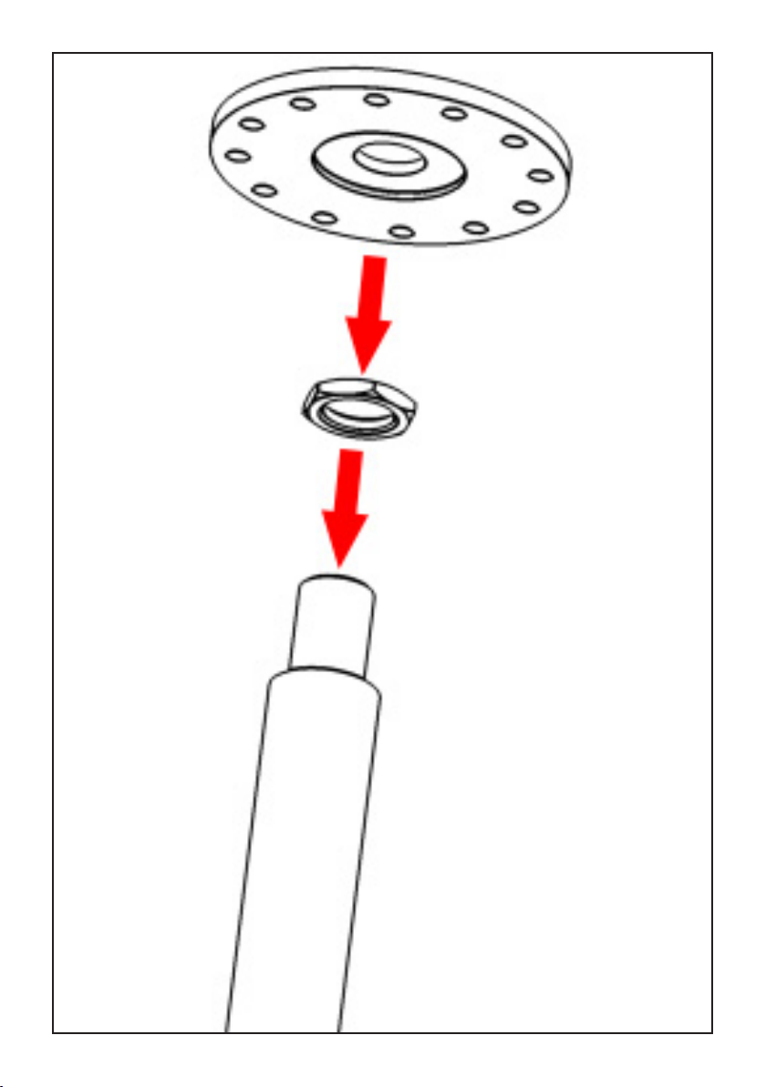
Fig. 1: Avvitare il dado e il disco sull’estremità del tubo.
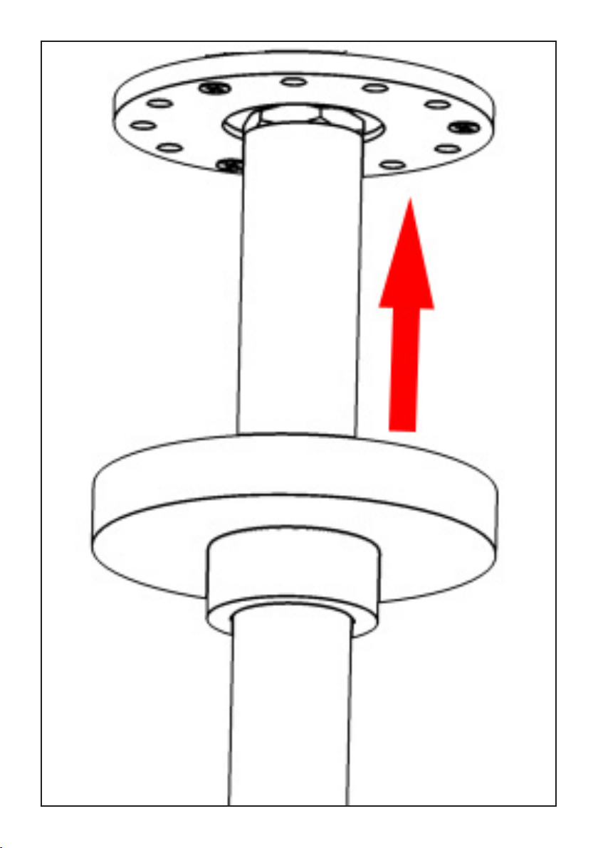
Fig. 2: Praticare i fori nel sotto ed inserire i tasselli in plastica, avvitare il tubo alla
rete idrica, utilizzando PTFE per garantire la tenuta. Inserire ed avvitare le viti no al
completo ssaggio.
Fig. 3: Far scorrere il carter di copertura no al sotto.
Fig. 4: Svitare le viti del carter ed estrarlo. Svitare il tappo. Svitare le viti e smontare il
tappo piatto. ATTENZIONE: non buttare le 4 viti, serviranno nuovamente.
Fig. 5-6: Posizionare il blocco cartuccia nel corpo incasso, facendo attenzione a centrare
la spina posteriore. Fissare il blocco cartuccia avvitando le quattro viti.
Dopo aver completato l’installazione del blocco cartuccia, aprire i rubinetti d’arresto e
vericare il corretto funzionamento del miscelatore. Controllare la mancanza di perdite
nell’impianto.
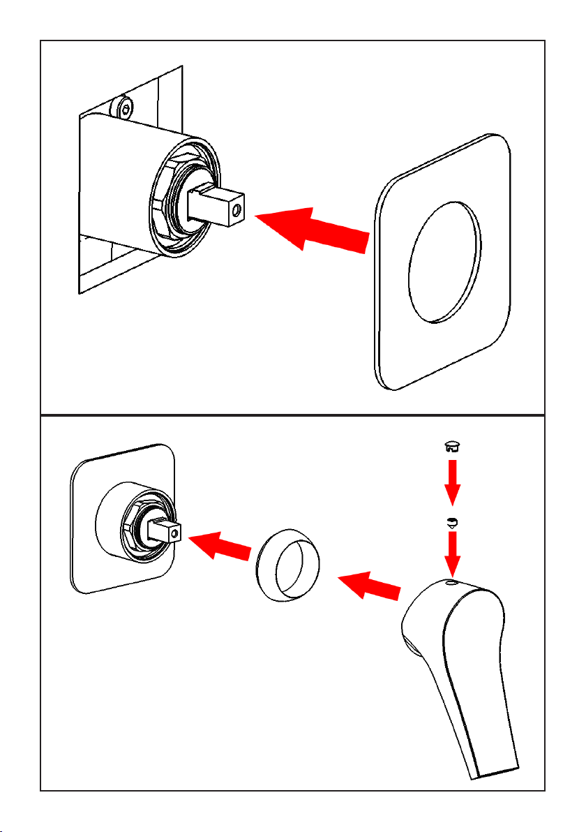
Fig. 7: Innestare la piastra sul blocco cartuccia.
Fig. 8: Avvitare la ghiera di copertura sul blocco cartuccia. Innestare la maniglia sull’asta
cartuccia ssandola con il grano. Posizionare il tappino di copertura foro.
PULIZIA
Per una corretta pulizia, lavare esclusivamente con acqua e sapone, risciacquare ed
asciugare con una pelle di daino e panno morbido. Evitare assolutamente l’impiego di
alcool, solventi, detersivi solidi o liquidi contenenti sostanze corrosive o acide, stronacci
con bre sintetiche, spugne abrasive, tamponi con li metallici, poichè potrebbero
alterare irreversibilmente le superci trattate.

EN
TECHNICAL DATA
Minimum dynamic pressure: 0.5 bar
Maximum operational pressure: 5 bar
Recommended operational pressure: 1-5 bar
It’s recommended to use a pressure reducer in case of
static pressure superior than 5 bar inside the waterpipe.
Maximum hot water temperature: 80°C
INSTALLATION, MAINTENANCE AND PRELIMINARY CHECKING PROCEDURE
In order to get your device work correctly and ne in time, must ensure compliance
with the mode of installation and maintenance described in this booklet. Relying on
a qualied plumber. Make sure that the system is free from all debris and impurities
existing.
INSTALLATION
Fig. 1: Screw the nut and the disc onto the tube.
Fig. 2: Drill holes in the ceiling and insert the plastic anchors, screw the hose to the water
supply, using PTFE to ensure a seal. Insert and tighten the screws until full attachment.
Fig. 3: Slide the cover casing to the ceiling.
Fig. 4: Unscrew the screws from the carter and remove it. Unscrew the cover. Unscrew
the screws and remove the at cover. ATTENTION: do not throw the 4 screws, you will
need them.
Fig. 5-6: Position the cartridge lock in the built-in body, being careful to center the rear
plug. Fit the cartridge lock by tightening the four screws.
After connecting the spout to the system, open the stopcocks and verify the correct
operation of the mixer. Check the lack of losses into the system.
Fig. 7: Insert the plate on the cartridge lock.
Fig. 8: Screw the cover ring onto the cartridge lock. Insert the handle on the cartridge
rod, xing it with the grub screw. Position the cover hole plug.
CLEANING
In order to get a correct cleaning, exclusiveny wash with soap and water, rewash and dry
with deerskin and a soft cloth. Avoid to use alcohol, solvents, solid or liquid detergents
made by corrosive or acid substances, towel made by synthetic materials, abrasive
sponges, because they could irreversibly alterate the treated surfaces.

FR
CARACTERISTIQUES TECHNIQUES
Pression dynamique minimale : 0.5 bar
Pression de service maximale : 5 bar
Pression de service recommandée : 1-5 bar
Il est recommandé d’utiliser un réducteur de pression en cas,
dans le système hydraulique, il y a des pressions statiques
supérieures à 5 bar.
Température maximum d’eau chaude : 80°C
RÈGLES D’INSTALLATION, ENTRETIEN ET VÉRIFICATIONS PRÉLIMINAIRES
Pour assurer le bon fonctionnement du produit et il puisse durer dans le temps, il est
nécessaire qu’ils soient remplies les procédures de installation et l’entretien dénies
dans la brochure. S’appuyer sur un plombier qualié. S’assures que les tuyauteries
soient nettoyées par toutes saletés et résidus.
INSTALLATION
Fig. 1: Vissez l’écrou et le disque sur le tube.
Fig 2: Percez des trous dans le plafond et insérer les chevilles en plastique, visser le
tuyau à l’alimentation en eau, en utilisant PTFE pour assurer l’étanchéité. Insérez et
serrez les vis de xation jusqu’au complet.
Fig. 3: Faites glisser le capot vers le plafond.
Fig. 4: Dévisser les vis du carter et le retirer. Dévissez le bouchon. Dévissez les vis et
retirez le bouchon plat. ATTENTION: ne jetez pas les 4 vis, vous en aurez encore besoin.
Fig. 5-6: Placez le blocage de la cartouche dans le corps encastré, en prenant soin de
centrer la che arrière. Fixez le blocage de la cartouche en serrant les quatre vis.
Une fois terminés l’installation du blocage de la cartouche et du bec, ouvrir le robinet
d’arrêt pour vérier le bon fonctionnement. Vérier l’absence de fuites.
Fig. 7: Insérez la palque sur le blocage de la cartouche.
Fig. 8: Vissez la bague de recouvrement sur le blocage de la cartouche. Insérez la
poignée sur la tige de la cartouche en la xant avec le grain. Positionner le bouchon
cache trou.
NETTOYAGE
An d’assurer un bon nettoyage, laver exclusivement avec eau et savon, rincer et
essuyer avec un chiffon doux. N’utiliser jamais alcool, solvants, de poudres à récurer
ni de nettoyants acides et éponges abrasives ou éponges métalliques car risquent de
causer des dommages irrémédiables.

Fig. 1

Fig. 2

Fig. 3

Fig. 4

Fig. 5
Fig. 6

Fig. 7
Fig. 8

SOSTITUZIONE CARTUCCIA
Chiudere le entrate dell’acqua. Estrarre il copriforo q, svitare il grano utilizzando una chiave
esagonale w e slare la maniglia e. Svitare il coprighiera r e la ghiera t, estrarre la cartuccia
y. Per il montaggio procedere in ordine inverso, assicurandosi che la base d’appoggio della
cartuccia sia accuratamente pulita. ATTENZIONE: Le istruzioni sono valide per i diversi
modelli di maniglia, il montaggio è concettualmente sempre uguale.
CARTRIDGE REPLACEMENT
Close the water inlets. Remove the hole cover q, unscrew the dowel using a hex wrench w
and remove the handle e. Unscrew the cap r and the ring nut t, remove the cartridge y.
To assemble, proceed in reverse order, making sure that the support base of the cartridge is
thoroughly clean. ATTENTION: The instructions are valid for the different models of handle;
the assembly is always the same.
REMPLACEMENT DE LA CARTOUCHE
Fermer les arrivées d’eau. Retirez le couvercle du trou q, dévissez la cheville à l’aide d’une
clé hexagonale w et retirez la poignée e. Dévisser le bouchon r et la bague t , retirer la
cartouche y. Pour le montage, procéder dans l’ordre inverse en s’assurant que la base de
support de la cartouche est parfaitement propre. ATTENTION: Les instructions sont valables
pour les différents modèles de poignée, l’assemblage est toujours le même.

Rev. 19/12//2022
Table of contents
Other IB RUBINETTERIE Bathroom Fixture manuals
Popular Bathroom Fixture manuals by other brands

Helvex
Helvex RM-27 installation guide

Signature Hardware
Signature Hardware DESTIN 948175 Installation

RIHO
RIHO SCANDIC NXT X203 installation manual

METHVEN
METHVEN MINIMALIST MK2 installation guide

Signature Hardware
Signature Hardware MODERN SLIDE BAR 948917 manual

METHVEN
METHVEN Waipori 01-8345 installation guide