IBA ibaBM-FOX-i-3o User manual


Page 2 Manual ibaBM-FOX-i-3o
ibaBM-FOX-i-3o - Manual
Issued by
iba AG
Koenigswarterstr. 44
90762 Fuerth, Germany
Tel.: + 49 (0)911 9 72 82-0
Sales -27
Support -14
R&D -13
FAX -33
Email: [email protected]
Web: www.iba-ag.com
Unless explicitly stated to the contrary, it is not permitted to pass on or copy this docu-
ment, nor to make use of its contents or disclose its contents. Any violation is treated
as an act liable for damages.
©iba AG 2009 all rights reserved.
ibaBM-FOX-i-3o - Manual V 1.4 en
We have checked that the contents of this manual match the hardware and software
described here. However, deviations cannot be fully ruled out, so that we cannot as-
sume any warranty should any deviations actually exist. This manual is regularly up-
dated. Necessary revisions are included in future editions, or can be downloaded from
the Internet.
The latest version is always available for downloading at:
http://www.iba-ag.com.
We would welcome any suggestions for improvements which you may have.
Version Date Revision Chapter / pages Author Gepr. Version HW/FW
V 1.4 05/11/09 Cover, Dimensional Drawing,
Contacts
©iba AG 2009

ibaBM-FOX-i-3o Manual Page 3
©iba AG 2009
Contents
This manual 4
1Introduction 5
2Package Contents 6
3System Requirements 6
4Installing the Device 6
5System Topologies 7
6Functionality 7
6.1 Device Views, Connectors and Switches ...................................... 8
6.2 LEDs ............................................................................................. 8
7Programming 9
8Technical Data and Environmental Conditions 9
8.1 Dimensional Drawing .................................................................. 10
9Accessories 11
10 Support and Contact 12

Page 4 Manual ibaBM-FOX-i-3o
This manual
This compact manual provides the information for installation and handling of the de-
vice ibaBM-FOX-i-3o.
For further information concerning the system integration and software configuration
please refer to the corresponding engineering manuals and / or software documenta-
tion of our software products used in conjunction with this device.
You can find the latest issue of this manual always on our website
http://www.iba-ag.com in the download area.
This manual uses several symbols which essentially have the following meanings:
Important hint or warning in order to avoid hazard against material or life.
A useful tip or clue to make your work easier.
This draws your attention to special features, such as exceptions to rules, etc.
A reference to additional documentation or more in-depth literature.
iba training courses
Hint for training courses by iba concerning related products or subjects
Copyright notice
Windows is a registered trademark of Microsoft Corporation.
Other product or company names mentioned in this manual may be brand names or
registered trademarks of the corresponding owner.
©iba AG 2009

ibaBM-FOX-i-3o Manual Page 5
©iba AG 2009
1Introduction
The ibaBM-FOX-i-3o device (Fiber Optics x 3) is designed to generate three parallel
optical output data streams from one incoming fiber optic signal data stream.
In addition, the incoming optical signal is refreshed (repeater functionality)
The maximum input baud rate can be up to 5.0 Mbit/s and can be used with the fol-
lowing iba devices/ PC-boards
TibaPADU-8, ibaPADU-16, ibaPADU-32
TibaPADU-8-O
TSLM Monitor
TibaPADU-8-ICP (only data stream to the PC)
TibaLink-SM-64-io, ibaLink-SM-128V-i-2o
TibaFOB x/4-F
TibaFOB-4i, ibaFOB-4, ibaFOB-4i-S
TibaFOB-io, ibaFOB-io-S
It is possible to monitor the data with a Notebook connected to the RJ45 jack via an
ibaCom-PCMCIA-F card (not for ibaPADU-8-ICP/ -8-M!).

Page 6 Manual ibaBM-FOX-i-3o
©iba AG 2009
2Package Contents
The package includes the following items:
TibaBM-FOX-i-3o device with 2-pole Phoenix connector (for power supply)
TibaBM-FOX-i-3o manual
3System Requirements
TPower supply 24 V DC
TSignal source (outputs of ibaPADU, ibaLink-SM- or ibaFOB card)
TSignal target (inputs of ibaPADU-8-O, ibaLink-SM- or ibaFOB card)
TPC, equipped with ibaFOB-card and software ibaPDA, ibaLogic or ibaQDR
TThe supported baud rates range from 2.0 Mbit/s up to 5 Mbit/s
4Installing the Device
Install:
Make sure the DIN-rail clip at the back of the device fits properly into the top edge of
the DIN-rail, then lightly press the device down – back into the DIN-rail. The device
will easily snap into the DIN-rail. After that connect the power supply and all necessary
connectors.
Removing the device:
First remove all connectors from the device.
With one hand press the top of the device slightly down to ensure that the device later
will be secure between both hands.
Place two fingers of the other hand under the bottom of the device and slightly push
the device upward. The device will easily remove from the DIN-rail.

ibaBM-FOX-i-3o Manual Page 7
5System Topologies
The ibaBM-FOX-i-3o provides the ability to multiply fiber optical links. This is possible
at each interconnection between iba devices, also between ibaPADU-8 and
ibaPADU-8-O devices. A variety of system topologies can be created. Applications can
vary from redundant I/O-systems, to measurement systems running in parallel to the
I/O system while reusing the same I/O devices. ibaBM-FOX-i-3o can also be simply
used for signal refreshing when fiber optic transmissions over 2000 m (6500 ft.) are
necessary.
6Functionality
The device provides the following functions:
T24 V DC power supply (18..32 V input voltage range).
TRugged, EMI-stable metal chassis with DIN-rail snap mount.
T3 status LEDs
TOne fiber optic input,
T3 fiber optic outputs
TSignal refreshing of the incoming data stream (bit refresh)
TDelay between input and output(s) max. 80 ns
©iba AG 2009

Page 8 Manual ibaBM-FOX-i-3o
6.1 Device Views, Connectors and Switches
©iba AG 2009
Frontview
Status LEDs
Run; Link; Error
24 V DC power supply input
connector, ICC=100 mA max.
(X14)
Notebook interface (X9)
Fiber optic input RX (X11)
Fiber optic outputs 1..3
TX1 (X16)
TX2 (X17)
TX3 (X18)
On top
Serial number and email
support address
6.2 LEDs
The three LEDs can be interpreted as follows.
LED Status Interpretation
Run
(green) blinking
off
When the device is connected to power and running
No power supply
Link
(yellow) on
off
Shows that a data stream with valid data is coming via on the fiber optic
input
No valid data or no data at all
Error (red) on
off
Broken fiber (the data stream is broken or the data is not valid)
No error (ERROR LED is cancelled if error disappears)

ibaBM-FOX-i-3o Manual Page 9
©iba AG 2009
7Programming
No programming or adjusting is necessary to operate the device.
8Technical Data and Environmental Conditions
Order no. f iba: 13.113500
Mechanical stability DIN IEC 68-2-6 (if DIN rail is mounted correctly)
Operating temperature: 0 °C to 50 °C (32 °F…122 °F)
Storage temperature: -25 °C to 70 °C (-13 °F…158 °F)
Transport temperature: -25 °C to 70 °C (-13 °F…158 °F)
Cooling: Self cooling
Mounting: DIN rail snap on mount
Humidity class: F, no moisture
Protection class: IP20
Power supply: 24 V DC +/-20 % not stabilized
Current consumption: max. 100 mA
Max. length of optical cable without repeater max. 2000 m (6500 ft.)
FO-cable
Coupling
62,5/125 µm
ST Lean
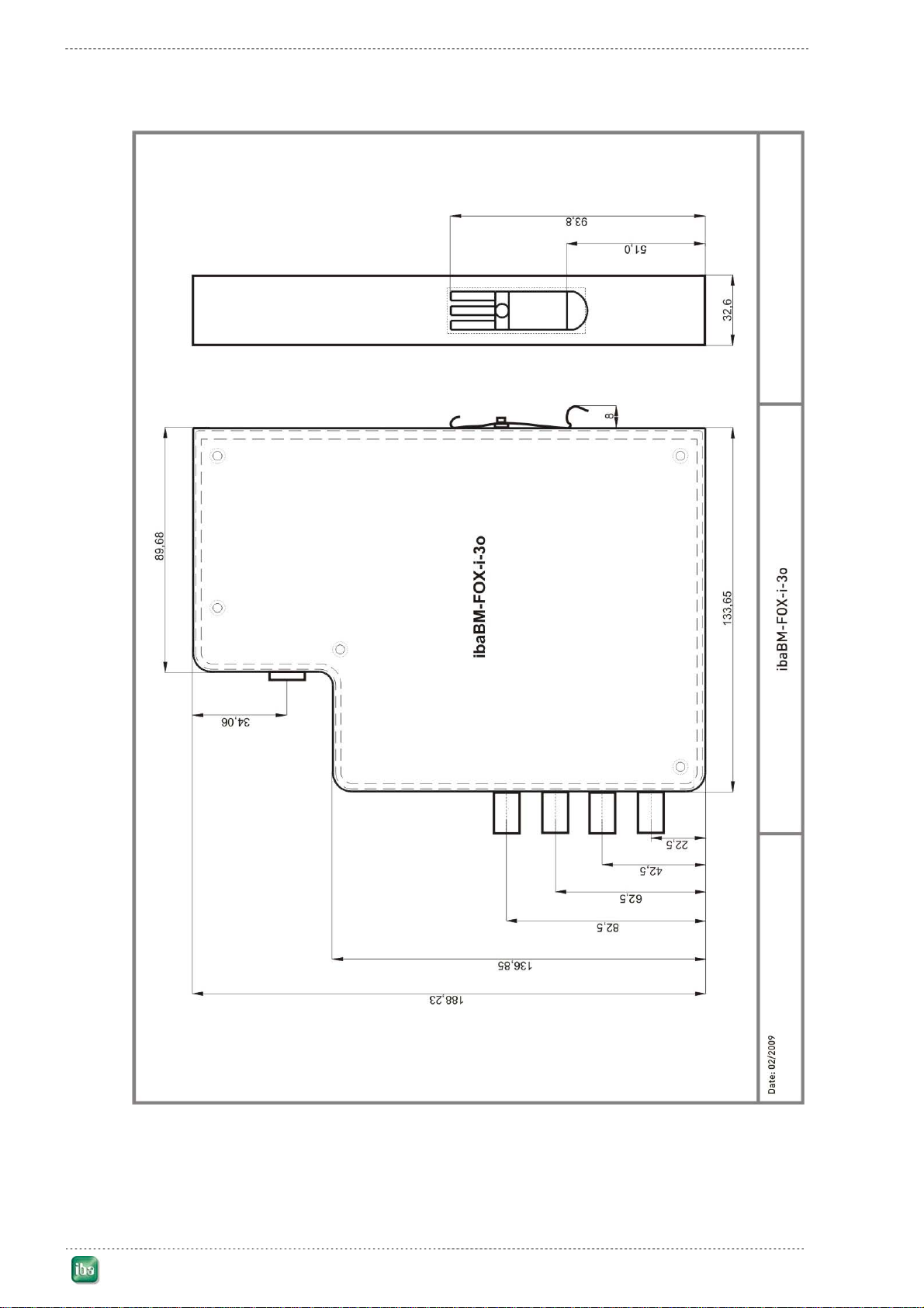
Dimensions in mm (Width x Height x Depth) 33 x 194 x 155 (incl. DIN rail clip)
Masses (incl. box and manual) 750 g
Fiber optic inputs / outputs:
Number of IOs 1 input + 3 outputs
Baud rates Between 2.0 and 5.0 Mbit/s
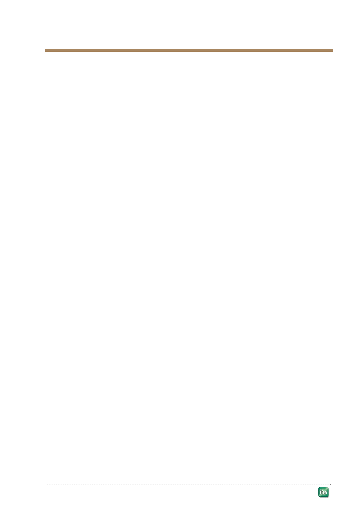
Usable iba devices and boards ibaPADU-8/-16/-32, ibaPADU-8-O, SLM, iba-
Link-SM-64-io, ibaLink-SM-128V-i-2o, ibaFOB-
x/4-F, ibaFOB-io, ibaFOB-4i / -4o
ibaPADU-8-ICP (only data stream to PC)

Page 10 Manual ibaBM-FOX-i-3o
©iba AG 2009
8.1 Dimensional Drawing
Dimensions given in mm

ibaBM-FOX-i-3o Manual Page 11
©iba AG 2009
9Accessories
Product iba order no. Comment
Fiber optic cable simplex with ST-jacks1 x 5 m 50.101050
For other fiber optic connectors, cabling and associated products refer to the iba product catalog.

Page 12 Manual ibaBM-FOX-i-3o
10 Support and Contact
For technical support or sales information, please contact your local iba representative
or call the following numbers:
Telephone: +49 911 97282-14
Fax: +49 911 97282-33
Email: [email protected]
For downloads of the latest software versions as well as hardware and software
manuals please use our web-site at: http://www.iba-ag.com/
Any feedback, comments or tips on errata in this documentation or suggestions for
improvement will be appreciated. Simply send an e-mail or fax to us, thank you for
your support.
©iba AG 2009
Headquarters
iba AG
Koenigswarterstrasse 44
90762 Fuerth / Bayern
Germany
Tel.: +49 (911) 97282-13
Fax: +49 (911) 97282-33
Contact: Harald Opel
Belgium,
Luxembourg,
Netherlands,
France, Spain
Great Britain
IBA-Benelux BVBA
Rivierstraat 64
B-9080 Lochristi
Belgium
Tel.: +32 9 226 2304
Fax: +32 9 226 2902
Contact: Roeland Struye
roeland.struye@iba-benelux.com
North America,
US Territories,
Caribbean, Ber-
muda
iba America, LLC
6845 Shiloh Road East,
Suite D-7
Alpharetta, GA 30005
USA
Tel.: +1 (770) 886-2318
Fax: +1 (770) 886-9258
Contact: Scott Bouchillon
Venezuela &
South America
iba LAT, S.A.
C.C San Miguel 1, Piso 1, Oficina 1.
Calle Neveri, Redoma de Harbor
YV 8050 Puerto Ordaz
Venezuela
Tel.: + 58 (286) 951 9666
Fax.: + 58 (286) 951 2915
Cell: + 58 (414) 386 0427
Contact: Eric Di Luzio
ibaChina,
ibaKorea,
ibaIndia,
ibaIndonesia
ibaMalaysia,
ibaThailand
ibaASIA GmbH & Co. KG
Saturnstrasse 32
90522 Oberasbach
Germany
Tel.: +49 (911) 969 4346
Fax: +49 (911) 969 4351
Contact: Mario Gansen
Table of contents