iBeam TE-360-3D User manual

INSTALLATION INSTRUCTIONS
iBEAM Vehicle Safety Systems®iBEAMUSA.com © COPYRIGHT 2018 METRA ELECTRONICS CORPORATION REV. 8/6/18 INSTTE-360-3D
TE-360-3D
CAUTION!
All accessories, switches, climate controls
panels, and especially air bag indicator lights must
be connected before cycling the ignition.
• Includes (4) high resolution 180-degree “fish-eye” cameras
• Exclusive “fish-eye” distortion correction
• Seamless 3D & 360° video merging
• Dynamic & intelligent view angle switching
• Includes calibration tools
• Independent camera calibration
• 3D video de-interlacing and noise reduction technology for CVBS
signal decoding
•
Digital 1080p recorder supporting up to 32GB USB flash drive or SD card
• Smart power management to preserve battery power
• Automatic recording for up to 28 hours
TOOLS REQUIRED
• Wire cutter • Crimp tool • Solder gun • Tape
• Connectors (example: butt-connectors, bell
caps, etc.)
TABLE OF CONTENTS
Introduction............................................................2
Safety tips...............................................................2
Installation ..........................................................2-3
Camera calibration............................................. 4-7
User settings .....................................................8-10
Digital video recording (DVR) .............................. 11
Specifications ........................................................12
Troubleshooting ....................................................12
Layout ....................................................................13
360-Degree 3D SVM Camera System with DVR
INTERFACE COMPONENTS
• TE-360-3D Interface
• TE-360-3D interface harness
• Remote control
• Remote control IR receiver
• Cameras (4)
• Camera extension cables (4)
• 22mm hole-saw
• Calibration tape
• Side camera adjustment tool
INTERFACE FEATURES
b

1.800.221.0932
|
iBEAMUSA.com
2
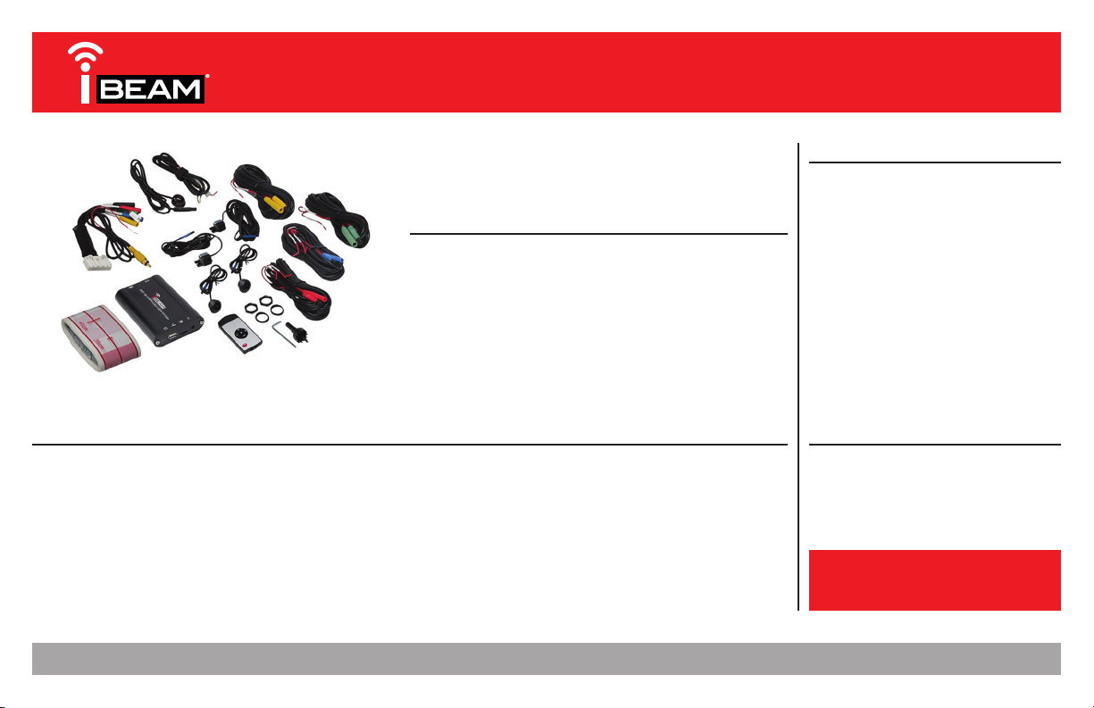
The I-Beam TE-360-3D is a 360-degree 3D Surround-View-Monitor (SVM) camera system that
utilizes the latest high resolution 180-degree “fish-eye” cameras to monitor and digitally record
a 360-degree surrounding view of the vehicle. Coupled with the latest software technology, all
cameras are seamlessly merged to form a single real-time image.
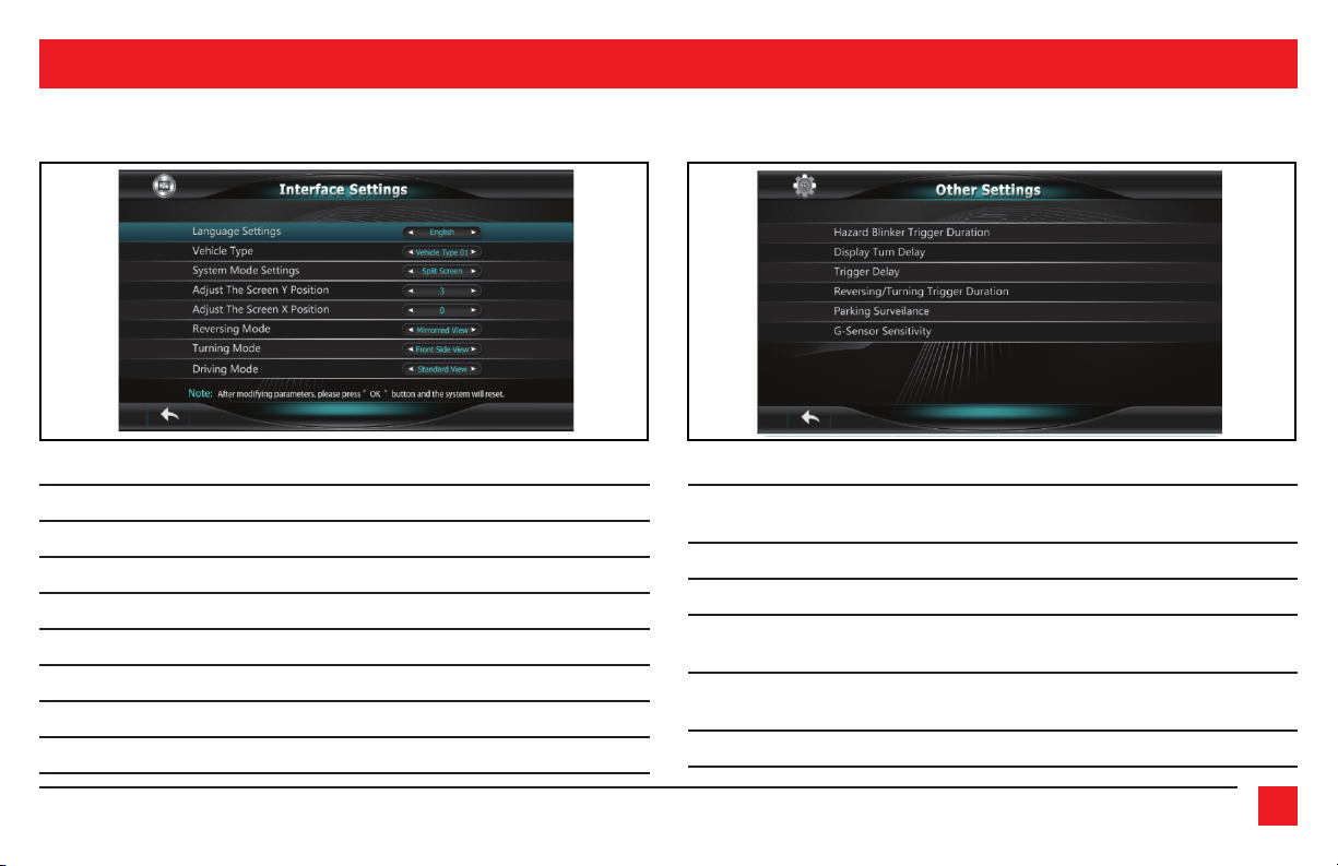
Activating the turn signals will show the respective left-side or right-side camera image. The
front camera image can be shown by a quick flash of the high-beams. While in reverse gear
the rear camera image will be shown, and will supersede all other cameras. All camera images
shown will be through either an aftermarket radio, or a stand-alone monitor (not provided).
Supporting up to a 32GB USB flash drive or SD card (both not included), the TE-360-3D can record
up to 28 hours of continuous 1080p recording, automatically while you are driving, and also
while the vehicle is parked (24-hr. video loop). Recorded videos can be easily retrieved and
played back, and used as evidence if need be.
INTRODUCTION INSTALLING THE TE-360-3D
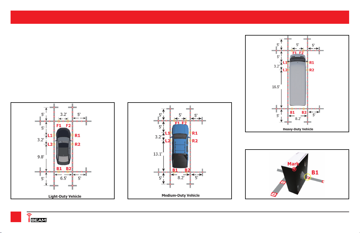
It is best to read the following steps beforehand to clearly understand what is to be expected,
before permanently modifying the vehicle. Also, when unpacking the TE-360-3D, do not damage
the box it came in as it will be used as a tool to calibrate the cameras.
Cameras:
If possible, try to keep all the cameras at the same vertical height to maintain the same image
aspect. The closer you can get to the same vertical height, the better the image will look when it
is seamed together.
• Front Camera: Using (2) stainless steel Phillips screws provided, install the camera labeled
“front” to a location that is in the center of the front of the vehicle. Leave the adjustment
screws loose until the camera has been adjusted. Once the camera has been adjusted,
tighten the screws. Route the cable into the vehicle, and then to the location where the
TE-360-3D interface will be installed at. Use caution not to run wires next to places that will
be hot, and also moving mechanisms.
• Rear Camera: Using (2) stainless steel Phillips screws provided, install the camera labeled
“rear” to a location in the center of the rear of the vehicle. The license plate area in most
vehicles is a good location. Leave the adjustment screws loose until the camera has been
adjusted. Once the camera has been adjusted, tighten the screws. Route the cable into the
vehicle, and then to the location where the TE-360-3D interface will be installed at.
• Side Cameras: Install the cameras labeled “left camera” and “right camera” to the bottom
of the left and right mirrors, preferably near the outside edge of the mirror. (Figure A) Once
a suitable location has been found, ensure that there are no obstructions inside the mirror,
and that the camera cable can be routed into the inside of the door. Using the 22mm hole-
saw provided, drill a hole in the mirror. Attach the rubber washer onto the camera,
Continued on the next page
SAFETY TIPS
• Serious traffic accidents may be caused by viewing or using the system while driving. It is
strongly recommended to not operate this system while driving.
• The TE-360-3D is a parking and driving assistant system which monitors the road situations
around the vehicle to eliminate blind spots, thus functioning as a visual guide for safe
parking and driving. There may be differences between what is being showed on the
display screen, and with the actual real surroundings of the vehicle. Please use the
TE-360-3D for what it is designed for, a tool to aid in safe parking and driving.

REV. 8/6/2018 INSTTE-360-3D 3
INSTALLING THE TE-360-3D (CONT.)
Camera location
example
From the TE-360-3D interface:
• Connect the Yellow RCA jack labeled AV-OUT to the aftermarket radio or stand-alone monitor
providing the camera image. Connect the Red wire to the reverse trigger wire from the radio/monitor.
Note 1: If using a radio as a display screen, this wire must be connected to trigger the
radio to display an image.
Note 2: If using a stand-alone monitor as a display screen which has an HDMI input, use
the HDMI output instead for a better image.
With the key in the off position:
then Insert the camera through the hole, but do not clip the camera into the hole just yet.
Route the cable into the door, and then to the location where the TE-360-3D interface will
be installed at. Leave the connector accessible inside the mirror to be able to disconnect the
camera if ever need be.
Note: A metal “U-shaped” adjustment tool is included with each camera. Make sure not to
accidentally throw this tool away while unpacking the cameras.
Remote control IR receiver:
• Install the IR receiver to a location where the remote control has a clear line of sight, and
also no more than 48-inches away from where the TE-360-3D will be installed at. Route the
cable to the location where the TE-360-3D interface will be installed at.
TE-360-3D interface:
From the cameras:
• Connect together the appropriately colored connectors by lining up the arrows and pushing in.
•
From the front camera, connect the
Red
wire to the positive trigger wire from the high beam light
.
• From the left-side camera, connect the
Red
wire to the positive trigger wire from the left-side
turn signal indicator.
• From the right-side camera, connect the
Red
wire to the positive trigger wire from the right-
side turn signal indicator.
• From the rear camera, connect the
Red
wire to the positive trigger wire from the reverse light
.
From the remote control IR receiver:
• Connect together the appropriately colored Black connectors by lining up the arrows and pushing in.
• Connect the Black wire to chassis ground.
• Connect the Yellow wire to battery power.
• Connect the Red wire to accessory power.
• Install the interface to a location that is hidden,
yet accessible to the owner of the vehicle. The
USB flash drive and SD card (not provided) will
connect directly into the interface.
• Connect the interface harness into the TE-360-3D.
(Figure A)

1.800.221.0932
|
iBEAMUSA.com
4
CAMERA CALIBRATION
Applying the calibration tools:
• Park the vehicle in a flat location, away from all obstacles. Apply the tape to the ground as shown. This is a very important
step and the tape must be placed as accurate as possible to create a distortion free, seamless image. Have patience with this
step. (Figure A, B, C)
• Separate the TE-360-3D product box. The product box has an inner and outer shell. Each shell should be placed at one of the (2)
reference points shown. Either B1 and B2 for the back camera, F1 and F2 for the front camera, L1 and L2 for the left camera, or R1 and
R2 for the right camera. Whichever reference points are chosen will dictate the first camera to be calibrated. It would be best if the
boxes were weighted down to avoid the wind from blowing them over. (Figure D)
Continued on the next page
(Figure A)
(Figure C)
(Figure B) (Figure D)

REV. 8/6/2018 INSTTE-360-3D 5
CAMERA CALIBRATION (CONT.)
Camera adjustment:
Having a Helper to help aid in adjusting the cameras is highly advisable, but not required. While
adjusting the front cameras, ensure both front doors are fully shut. Also note, having the front
windows down would make it to where adjustments can be made from inside the vehicle.
• Turn the key (or push to start button) to the accessory position to power on the TE-360-3D.
•
Press and hold the “Left-Arrow” button on the remote control until the left camera comes on
.
•
Rotate the left camera so it will show an image from the rear of the vehicle. Clip the camera in
.
• Insert the metal “U-shaped” tool provided into the front and rear holes in the bezel of the
camera. (Figure A)
• Pull the tool and camera towards the left rear of the vehicle. The image on the screen should
not show the vehicle. It should be just slightly away from the vehicle. Looking at the camera
it should appear to be aiming between the front and rear tires, away from the vehicle. Keep
adjusting the camera as needed to ensure the best image possible. The goal is to be able to
view traffic in the vehicles blind spot. Once a satisfactory image is provided, continue onto
the right camera. Once the right camera has
been adjusted, ensure that both the left and
right cameras have an equal looking image.
•
After the side cameras have been adjusted,
continue on to the front and rear cameras. The
front camera can be activated by pressing the
“Up-Arrow” button on the remote control. The
rear camera can be activated by pressing and
holding the “Down-Arrow” button on the remote
control until the rear camera is displayed
.
Continued on the next page
(Figure A)
Button Description Function
(1) Mode Enter settings menu.
In SVM Mode, long press for 2 seconds to enter 4-channel recording.
(2) Up In Menu Mode, selects last menu option.
In SVM Mode, short press enters front camera mode.
Press again to get back to SVM mode.
(3) Right In SVM Mode, long press to enter right camera mode.
(4) Down In Menu Mode, selects next menu option.
In SVM Mode, long press to enter reverse camera mode.
(5) Left In SVM Mode, long press to enter left camera mode.
(6) Confirmation Confirm selected option.
Remote control functions:

1.800.221.0932
|
iBEAMUSA.com
6
Camera calibration parameter settings:
• Press the “Mode” button to access the settings menu. The default password is “360”.
• Enter the Camera Calibration menu.
• Enter 360 Tuning to access the parameter settings.
• Select the correct size of the vehicle and adjust the vehicle position as needed.
•
Adjust the shadow area for each of the cameras as needed. Each increment is equal to 2-inches.
The shadow area will help to eliminate the vehicle from being portrayed in the final image for
applications where it is not possible to angle the cameras away from the vehicle
.
• Adjust the merging angle and range as needed. Try to keep this setting as close to default
as possible. Adjusting this too much will distort the seamed image. The merging angle is to
be used for instances where the front or rear camera image does not meet up with the side
camera image. The merging range is for adjusting the side cameras.
Continued on the next page
CAMERA CALIBRATION (CONT.)

REV. 8/6/2018 INSTTE-360-3D 7
Camera calibration:
Tip! The use of an HDTV, 32” and higher, will improve the ease and accuracy of the calibration process.
• From the Camera Calibration menu, enter the desired camera to be calibrated.
• The calibration process will start when the cursor starts blinking.
• Move the cursor to location 1 via the remote control. Press and hold to move quickly.
• Once at location 1, press “OK” to mark the calibration point in the screen.
• Continue onto the next calibration point, in order, 2 through 8.
• Press the “Mode” button to go back to the previous calibration point if need be.
• Once done, proceed onto the next camera to be calibrated. The TE-360-3D product box
shells will need to be moved to the reference points for the next camera to be calibrated.
• Continue the process until all cameras have been calibrated. Once completed, press
“Merging Computation”, then “OK”, to begin the merging process. The merging process will
take approximately 2 minutes to complete. The system will reboot automatically after the
merging process is complete.
CAMERA CALIBRATION (CONT.)

1.800.221.0932
|
iBEAMUSA.com
8
USER SETTINGS
Viewing Modes
Menu User Settings Window Configuration
Function Settings
Continued on the next page
Menu Item List Options Description
Turn Signal Trigger ON / OFF
Activate Turn Signal ON / OFF
Emergency Blinker
Trigger ON / OFF
Guideline Assistance ON / OFF
3D Dynamic Angle Function ON / OFF
Will activate the appropriate left or right camera once a
turn signal has been activated
Allows the turn signals to trigger the radio/monitor to display
an image, if it is not already displaying the TE-360-3D image
Allows the hazard switch to override the display
on the radio/monitor
Display a guideline overlay while in reverse gear
Sets either a dynamic or static angle image

REV. 8/6/2018 INSTTE-360-3D 9
USER SETTINGS (CONT.)
Interface Settings: Other Settings:
Menu Item List Options Description
Language Setting English / Chinese Set desired language
Vehicle Type Vehicle Type Set 3D car model
System Mode Setting Split Screen
Adjust The Screen Y Position -9 ~ +9 Pixel Adjusts the horizontal position
Adjust The Screen X Position -9 ~ +9 Pixel Adjusts the vertical position
Reversing Mode Mirrored View Set a different view while in reverse gear
Turning Mode Front Side View Set a different view while turning
Driving Mode Standard View Set a different view while driving
Menu Item List Options Description
Hazard Blinker 1Min/3Min/5Min/
Trigger Duration 3S/5S/30S
Display Turn Delay 30S/1Min/3Min/5Min For setting the delay to the radio/monitor
Trigger Delay 30S/1Min/3Min/5Min To delay the turn signal and reverse trigger
Reversing / Turning
Trigger Duration 30S/1Min/3Min/5Min
Parking Surveilance Disabled/Delayed/ Surveillance mode after vehicle
3/Min/5Min has been parked
G-Sensor Sensitivity Middle/High/Low Adjust sensitivity for the G-Sensor
Sets the Emergency Blinker duration time once the
Emergency Blinker Trigger feature has been turned to “On”
Sets the duration time for the radio/monitor
after a trigger event

1.800.221.0932
|
iBEAMUSA.com
10
Video Settings: Upgrade & Restore
USER SETTINGS (CONT.)
Menu Item List Options Description
Saturation -9~+9 Adjust video saturation
Brightness -9~+9 Adjust video brightness
Contrast -9~+9 Adjust video contrast
Sharpness -7~+8 Adjust video sharpness
Menu Item List Options Description
Default - N/A
System Restore Default or User Preference User Preference - To restore user
preferences
Upgrade Options Upgrade 3D Mode For upgrading firmware in the
TE-360-3D
Version Information -9~+9 Check Hardware /
Firmware / Software version

REV. 8/6/2018 INSTTE-360-3D 11
DIGITAL VIDEO RECORDING (DVR)
Recording Functions
1. Long press the “Mode” button to switch to the recording system menu.
2. Press the “OK” button to stop the current recording.
3. Use the “Up/Down” buttons to navigate between the recorded files.
4. Press the “OK” button to select the recorded file to playback.
5. The (4) cameras can be enlarged to full screen mode by pressing the “Left /Right/Up/
Down” buttons.
Recording Settings
Menu Item List Options Description
Date To change system time
Language English / Chinese To change system language
Time Watermark ON / OFF To apply a time stamp on the recorded video
Format Format SD card To format SD Card
Factory Reset To reset the default settings
Firmware Info To check firmware version

1.800.221.0932
|
iBEAMUSA.com
12
Picture after merging is not accurate or seamless
• This problem is usually caused by the installation position of the cameras, and can happen
more often with smaller size vehicles. The picture captured by the cameras will be poor,
and so the calibration error will magnify this. This issue could also be the result of not
enough care taken while calibrating the cameras. Recalibrate the cameras to possibly solve
this problem.
A portion of the picture after merging is mirrored
• If a factory camera will be used with the TE-360-3D, please confirm whether the image
from the sensor is mirrored or not. If mirrored, please choose the mirror function in the
menu.
The corner portion of the display is blank
• This problem may be caused by the location of the camera. The camera may be too close to
the ground. Move the camera to a higher position.
The merging result has failed
• Ensure the proper vehicle size has been selected before starting the camera calibration. The
vehicle type parameter must be set according to the size of the vehicle. A vehicle mismatch
could be the result of such an issue.
• Ensure the proper camera being calibrated has been chosen. While calibrating the rear
camera, the front camera could have been mistakenly chosen, or opposite. Likewise for the
side cameras.
SPECIFICATIONS TROUBLESHOOTING
Camera
Trigger Input
G-sensor
Recording
Disk Capacity
Power Consumption
Dimension
Weight
Environments
Voltage Tolerance
Video Interface BMW Mini Connector
Input / Output Impedance 75
Ω
Amplitude Typical 1Vpp. 1.2Vpp Maximum
Bandwidth 27M
Sampling Frequency 74.52MHZ
Resolution 1280x720 @ 30fps
Signal Standard AHD2.0 (Nextchip)
SNR 83.5bB
High Beam Optional
Left/Right Turn Yes
Reverse Yes
BM250E Bosch
Algorithm H.264 Baseline @ L3.1
Resolution 1080p @ 15fps
Bitrates 5MBPS, 3GBYTE / Hour
Recording Media USB / SD Card
SD Card 32G SDIO2.0 / SDIO3.0
USB 64G USB2.0
4-CH DVR + SVM mode 490mA
Sleep Mode <3mA
L X W X H 5 x 3 1/4 x 1 (interface)
.49lb
Normal Working -86˚F~ +185˚F
Storage -104˚F~ +221˚F
Relative Humidity 0~95%
Working Voltage 9.5V DC~ 36V DC
Type Specifications

REV. 8/6/2018 INSTTE-360-3D 13
L AYO UT

1.800.221.0932
|
iBEAMUSA.com
14

REV. 8/6/2018 INSTTE-360-3D 15

INSTALLATION INSTRUCTIONS
KNOWLEDGE IS POWER
Enhance your installation and fabrication skills by
enrolling in the most recognized and respected
mobile electronics school in our industry.
Log onto www.installerinstitute.com or call
800-354-6782 for more information and take steps
toward a better tomorrow.
®
Metra recommends MECP
certified technicians
IMPORTANT
If you are having difficulties with the installation of this product,
please call our Tech Support line at 1-800-253-TECH. Before
doing so, look over the instructions a second time, and make
sure the installation was performed exactly as the instructions
are stated. Please have the vehicle apart and ready to perform
troubleshooting steps before calling.
iBEAM Vehicle Safety Systems®iBEAMUSA.com © COPYRIGHT 2018 METRA ELECTRONICS CORPORATION REV. 8/6/18 INSTTE-360-3D
TE-360-3D
Table of contents
Other iBeam Digital Camera manuals