manuals.online logo
Brands
  1. Home
  2. •
  3. Brands
  4. •
  5. FasTest
  6. •
  7. Cables And Connectors
  8. •
  9. FasTest 60V Series User manual

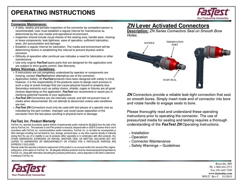
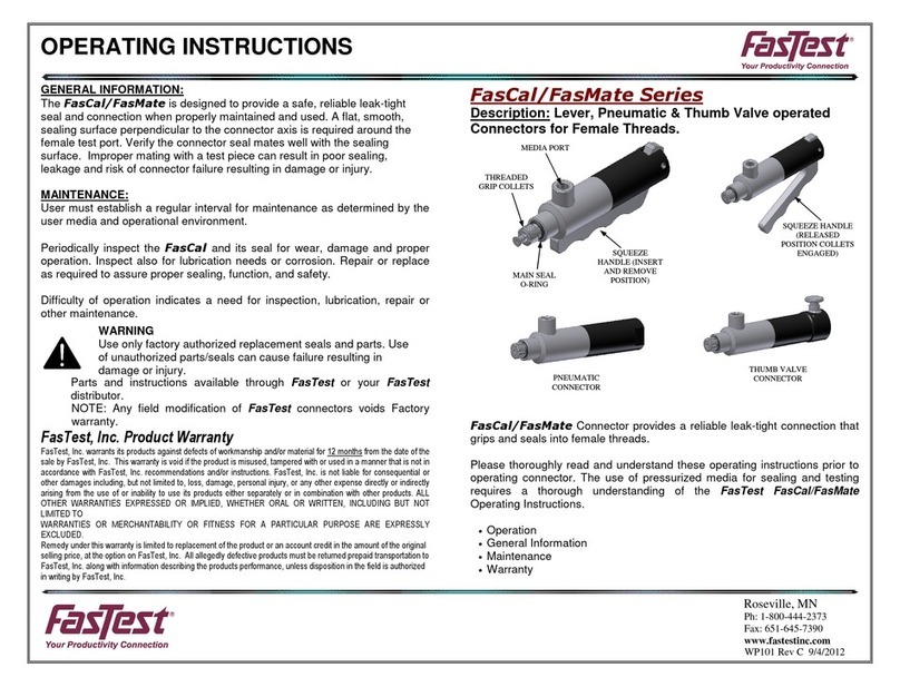
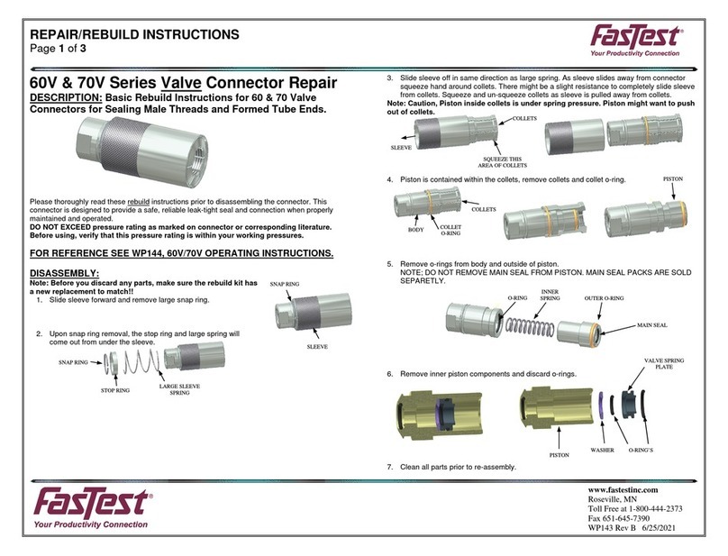
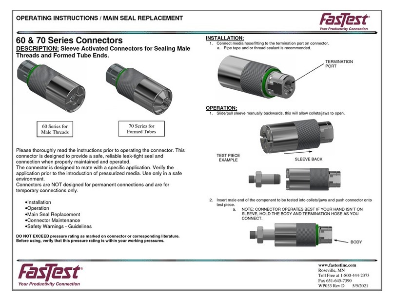
FasTest 60V Series User manual

OPERATING INSTRUCTIONS / MAIN SEAL REPLACEMENT
Page 1 of 3
www.fastestinc.com
Roseville, MN
Toll Free at 1-800-444-2373
Fax 651-645-7390
WP144 Rev B 6/25/2021
60 Series for
Male Threads
70 Series for Tube
Configurations
COLLETS
SLEEVE BACK
COLLETS
OPEN
BODY
TERMINATION
PORT
60V & 70V Series Valve Connectors
DESCRIPTION: Sleeve Activated Connectors for Sealing Male
Threads and Formed Tube Ends.
CAUTION: 60V & 70V Connectors are internally valved. Disconnecting
while pressurized can cause rapid separation. Termination pressure
should be relieved prior to disconnecting connector.
Connecting while pressurized is doable but not recommended.
Example of connection forces; At 80psi with a Body Size 3 connector
the force to connect is approximately 44 lbs.
Body Size 4 connector is approximately 56 lbs. at 80psi.
Please thoroughly read the instructions prior to operating the connector. This
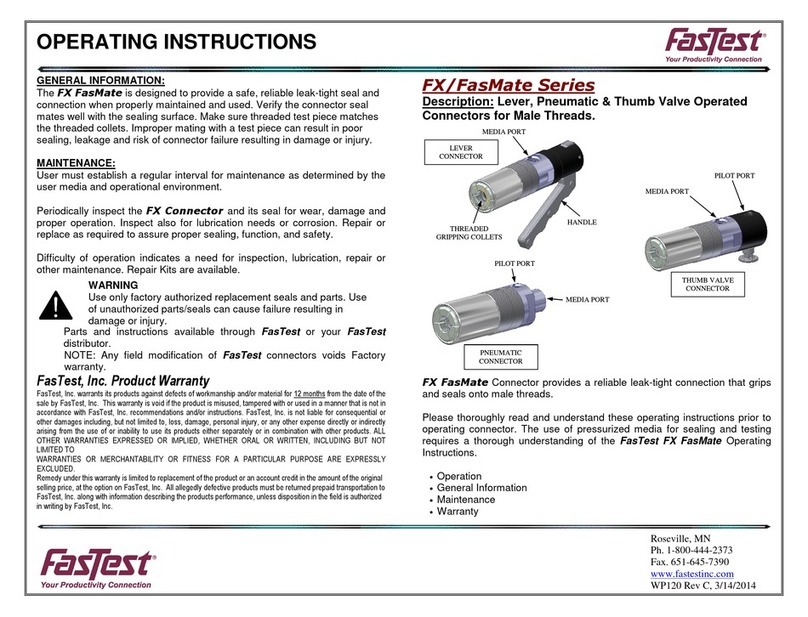
connector is designed to provide a safe, reliable leak-tight seal and
connection when properly maintained and operated.
•The connector is designed to mate with a specific application. Verify the
application prior to the introduction of pressure or processing. Use only in
a safe environment. Safety chains and guards are recommended for all
applications.
•Connectors are NOT designed for permanent connections and are for
temporary connections only.
DO NOT EXCEED pressure rating as marked on connector or
corresponding literature. Before using, verify that this pressure rating is
within your working pressures.
•Installation
•Operation
•Main Seal Replacement
•Connector Maintenance
•Safety Warnings - Guidelines
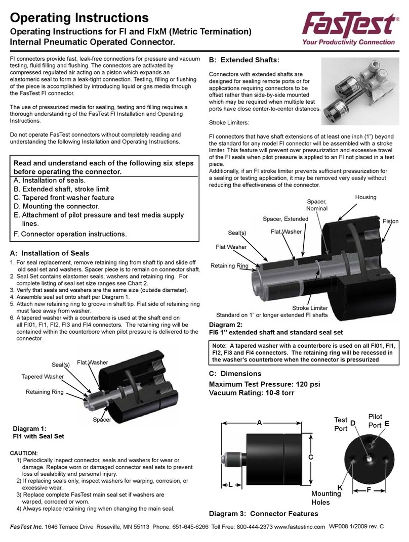
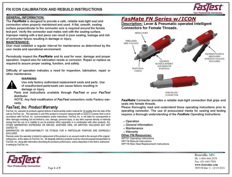
INSTALLATION:
1. Connect media hose/fitting to the termination port on connector.
a. Pipe tape and or thread sealant is recommended.
OPERATION:
1. Slide sleeve back and collets will open.
2. Insert male end of the component to be tested into collets and press
against connector. Spring action forces knurled sleeve forward, collaps-
ing collets to the gripping and sealing position.
3. Note to Operator; The Type 60/70 Connector will
connect better when you do the following. Hold exposed
area of Body at termination end of connector. Try to
keep hands free from the sleeve as you connect to your
test piece.
OPERATING INSTRUCTIONS / MAIN SEAL REPLACEMENT
Page 2 of 3
www.fastestinc.com
Roseville, MN
Toll Free at 1-800-444-2373
Fax 651-645-7390
WP144 Rev B 6/25/2021
HOLD BODY
HERE
TEST PIECE
GREEN RING
SLEEVE BACK,
JAWS OPEN
MAIN SEAL
4. Attempting to connect while connector is still pressurized is doable but
not recommended.
NOTE: DO NOT FORCE CONNECTOR ONTO TEST PART WHEN
CONNECTING. THE COLLETS SHOULD EASILY MATE WITH TEST
PIECE. FORCING THE CONNECTOR WILL RESULT IN POOR SEALING
AND POSSIBLE LEAKAGE. DO NOT TURN OR ROTATE CONNECTOR
AFTER THE COLLETS HAVE GRIPPED TEST PART. DAMAGE TO TEST
PIECE AND THE CONNECTOR’S INTERNAL PARTS MAY RESULT.
5. When connector is properly connected the green indicator ring will be
visible.
a. Tug on the connector near the termination port to assure
proper engagement and gripping before introduction of
pressurized media.
6. Activate test media through connector termination port. Pressure will
enhance the seal.
7. To disconnect from test piece, deactivate test pressure. Slide knurled
sleeve away from test piece to expand collets. Remove connector from
test piece.
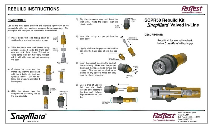
MAIN SEAL REPLACEMENT:
NOTE: IN MOST CASES THE MAIN SEAL CAN BE EXTRACTED AND
REPLACED IN THE STEPS THAT FOLLOW. IF CONNECTOR MUST BE
DIS-ASSEMBLED TO REPLACE MAIN SEAL, SEE INSTRUCTION WP143.
1. Slide sleeve back allowing collets/jaws to open. This will help expose
the end of the piston to extract the main seal.
2. Using a pick like tool or small flat blade screwdriver, remove the main
seal from piston and discard.
3. Use caution not to scratch the main seal groove surfaces in piston.
4. Install new main seal using your fingers or a non-marring tool. DO
NOT LUBRICATE NEW SEAL!
5. Make sure main seal is properly seated.
OPERATING INSTRUCTIONS / MAIN SEAL REPLACEMENT
Page 3 of 3
www.fastestinc.com
Roseville, MN
Toll Free at 1-800-444-2373
Fax 651-645-7390
WP144 Rev B 6/25/2021
MAINTENANCE:
Periodically inspect connector and seal for proper operation. Repair or
replace parts as required to assure positive sealing and performance.
Establish a regular interval for lubrication. The media and environment
will be determining factors in establishing this interval to prevent dryness
and/or corrosion.
Difficulty of operation after continual use indicates need for lubrication or
other maintenance. Repair parts, instructions and tools are available.
Please contact your FasTest Distributor or the factory for assistance.
Safety Warnings – Guidelines:
•If instructions are not completely understood by operator or components are
missing, contact FasTest before attempting use of the connector.
•Application Safety: All FasTest products have been designed with safety in mind;
however, it is the responsibility of the user to design each process in such a way to
avoid mishaps that can cause physical hazard or property loss. Secondary
restraints such as safety chains, shields, cages, or fixtures are all good choices
depending on the application. FasTest can recommend or assist you in clarifying
potential hazards of your application.
•FasTest 60/70 Series Valve connectors are internally valved to prevent loss of
media when disconnected. FasTest recommends that any connection or
disconnection be made only when pressure is reduced to ambient.
•FasTest 60/70 Series Valve connectors must only be used with test pieces of a
specific size as indicated by the part number. Improper use may separate the
connector from the test piece resulting in physical harm or damage.
FasTest, Inc. Product Warranty
FasTest, Inc. warrants its products against defects of workmanship and/or material for 12 months from the date of the
sale by FasTest, Inc. This warranty is void if the product is misused, tampered with, or used in a manner that is not in
accordance with FasTest, Inc. recommendations and/or instructions. FasTest, Inc. is not liable for conse uential or
other damages including, but not limited to, loss, damage, personal injury, or any other expense directly or indirectly
arising from the use of or inability to use its products either separately or in combination with other products. ALL
OTHER WARRANTIES EXPRESSED OR IMPLIED, WHETHER ORAL OR WRITTEN, INCLUDING BUT NOT
LIMITED TO WARRANTIES OR MERCHANTABILITY OR FITNESS FOR A PARTICULAR PURPOSE ARE
EXPRESSLY EXCLUDED.
Remedy under this warranty is limited to replacement of the product or an account credit in the amount of the original
selling price, at the option on FasTest, Inc. All allegedly defective products must be returned prepaid transportation to
FasTest, Inc. along with information describing the products performance, unless disposition in the field is authorized in
writing by FasTest, Inc.

This manual suits for next models

1

Other FasTest Cables And Connectors manuals

FasTest TWISTMATE Series User manual

FasTest

FasTest TWISTMATE Series User manual

FasTest FE001 Series Guide

FasTest

FasTest FE001 Series Guide

FasTest ZN Series User manual

FasTest

FasTest ZN Series User manual

FasTest FasCal Series User manual

FasTest

FasTest FasCal Series User manual

FasTest 60V Series User manual

FasTest

FasTest 60V Series User manual

FasTest 60 Series User manual

FasTest

FasTest 60 Series User manual

FasTest 60 Series User manual

FasTest

FasTest 60 Series User manual

FasTest FasMate Series User manual

FasTest

FasTest FasMate Series User manual

FasTest FI Series User manual

FasTest

FasTest FI Series User manual

FasTest ICON 60 User manual

FasTest

FasTest ICON 60 User manual

FasTest FasMate Series User manual

FasTest

FasTest FasMate Series User manual

FasTest FN Series User manual

FasTest

FasTest FN Series User manual

FasTest SnapMate SCPR50 User manual

FasTest

FasTest SnapMate SCPR50 User manual

FasTest FI Series User manual

FasTest

FasTest FI Series User manual

Popular Cables And Connectors manuals by other brands

Techno IOTH210 quick start guide

Techno

Techno IOTH210 quick start guide

Well SPLT-HDMI1.4/4-WL user manual

Well

Well SPLT-HDMI1.4/4-WL user manual

Staubli ID/B16BV-NS-A Assembly instructions

Staubli

Staubli ID/B16BV-NS-A Assembly instructions

Philips SWV2825W Specifications

Philips

Philips SWV2825W Specifications

Fujitsu UTY-XCBXZ2 installation manual

Fujitsu

Fujitsu UTY-XCBXZ2 installation manual

SMA EXTANT-40 Quick reference guide

SMA

SMA EXTANT-40 Quick reference guide

PureTools PT-SP-DP12 user manual

PureTools

PureTools PT-SP-DP12 user manual

ClickTronic 60806 user manual

ClickTronic

ClickTronic 60806 user manual

Wing & Sons CQ TP4VGA user manual

Wing & Sons

Wing & Sons CQ TP4VGA user manual

SY SY-HS12 installation guide

SY

SY SY-HS12 installation guide

Leviton Lev-Lok MT528 quick guide

Leviton

Leviton Lev-Lok MT528 quick guide

Lindy 38274 user manual

Lindy

Lindy 38274 user manual

Philips SWV2204NB Specifications

Philips

Philips SWV2204NB Specifications

Brugg CALPEX-Big-T-I-L instruction manual

Brugg

Brugg CALPEX-Big-T-I-L instruction manual

Sony XDCA-FS7 Service manual

Sony

Sony XDCA-FS7 Service manual

CYP qu-2-4k22 Operation manual

CYP

CYP qu-2-4k22 Operation manual

HARTING Han 09 10 004 3100 manual

HARTING

HARTING Han 09 10 004 3100 manual

Philips hue 17368 PN Series user manual

Philips

Philips hue 17368 PN Series user manual

manuals.online logo
manuals.online logoBrands
  • About & Mission
  • Contact us
  • Privacy Policy
  • Terms and Conditions

Copyright 2025 Manuals.Online. All Rights Reserved.