IBM 7383 Installation and maintenance instructions

System x3500 M4
Type 7383
Installation and Service Guide


System x3500 M4
Type 7383
Installation and Service Guide

Note
Before using this information and the product it supports, read the general information in
Appendix D, “Getting help and technical assistance,” on page 449, “Notices” on page 453, the
Warranty Information document, and the Safety Information and Environmental Notices and User Guide
documents on the IBM Documentation CD.
Sixth Edition (May 2013)
© Copyright IBM Corporation 2013.
US Government Users Restricted Rights – Use, duplication or disclosure restricted by GSA ADP Schedule Contract
with IBM Corp.

Contents
Safety ...............vii
Guidelines for trained service technicians ....ix
Inspecting for unsafe conditions ......ix
Guidelines for servicing electrical equipment . . x
Safety statements ............xi
Chapter 1. The IBM System x3500 M4
Type 7383 server ...........1
The IBM Documentation CD .........3
Hardware and software requirements .....3
The Documentation Browser ........3
Related documentation ...........4
Notices and statements in this document .....5
Server features and specifications .......6
What your server offers...........9
Reliability, availability, and serviceability ....13
IBM Systems Director ...........14
Server controls, LEDs, and power .......15
Front view..............15
Operator information panel ........17
Light path diagnostics panel........18
Rear view ..............19
Server power features ..........22
Turning on the server .........22
Turning off the server .........23
Chapter 2. Installing optional devices 25
Instructions for IBM Business Partners .....26
Sending DSA data to IBM .........26
Server components ............27
System-board internal connectors ......27
System-board external connectors ......29
System-board switches and jumpers .....29
System-board LEDs and controls ......31
Hard disk drive backplane connectors ....32
Installation guidelines ...........34
System reliability guidelines ........36
Working inside the server with the power on . . 36
Handling static-sensitive devices ......37
Opening the bezel media door ........37
Removing the left-side cover ........39
Removing the air baffle ..........40
Removing the fan cage assembly .......41
Installing a simple-swap fan .........43
Hard disk drive installation .........45
Installing a 2.5-inch hot-swap hard disk drive . . 52
Installing a 3.5-inch hot-swap hard disk drive . . 53
Installing a 3.5-inch simple-swap hard disk drive 55
Installing a DVD drive .........56
Installing an optional tape drive ......58
Memory module installation.........59
DIMM installation sequence ........63
Memory mirrored channel ........63
Memory rank sparing ..........64
Installing a DIMM ...........65
Installing a PCI-X bracket..........67
Installing an adapter ...........70
Installing an adapter on the PCI-X bracket . . . 72
Installing an optional ServeRAID adapter memory
module ................74
Installing a RAID adapter battery or flash power
module remotely in the server ........75
Installing the microprocessor 2 expansion board . . 77
Installing a microprocessor and heat sink ....83
Thermal grease ............89
Installing a hot-swap power supply ......90
Installing a USB embedded hypervisor flash device 93
Completing the installation .........94
Replacing the fan cage assembly ......95
Replacing the air baffle .........97
Replacing the left-side cover........98
Connecting the cables ..........99
Updating the server configuration .....100
Chapter 3. Configuration information
and instructions ..........101
Updating the firmware ..........101
Configuring the server ..........102
Using the ServerGuide Setup and Installation
CD................104
ServerGuide features .........104
Setup and configuration overview ....105
Typical operating-system installation . . . 105
Installing your operating system without
using ServerGuide..........106
Using the Setup utility .........106
Starting the Setup utility .......106
Setup utility menu choices .......107
Passwords ............111
Using the Boot Manager.........113
Starting the backup server firmware .....113
The UpdateXpress System Pack Installer . . . 114
Changing the Power Policy option to the default
settings after loading UEFI defaults .....114
Using the integrated management module. . . 115
Using the remote presence and blue-screen
capture features ...........116
Obtaining the IMM host name......117
Obtaining the IP address for the IMM . . . 117
Logging on to the web interface .....118
Using the embedded hypervisor ......119
Configuring the Ethernet controller .....120
Enabling Features on Demand Ethernet software 120
Enabling Features on Demand RAID software 120
Configuring RAID arrays ........120
IBM Advanced Settings Utility program . . . 121
Updating IBM Systems Director ......121
Installing a newer version .......122
Installing updates with your management
server is connected to the Internet ....122
© Copyright IBM Corp. 2013 iii

Installing updates with your management
server is not connected to the Internet . . . 122
Updating the Universal Unique Identifier
(UUID) ..............123
Updating the DMI/SMBIOS data......125
Chapter 4. Troubleshooting .....129
Start here...............129
Diagnosing a problem .........129
Undocumented problems ........131
Service bulletins ............132
Checkout procedure ...........132
About the checkout procedure.......132
Performing the checkout procedure .....133
Diagnostic tools ............134
Light path diagnostics .........136
Light path diagnostics LEDs ......137
Power-supply LEDs ..........142
System pulse LEDs ..........143
Event logs .............144
Viewing event logs through the Setup utility 145
Viewing event logs without restarting the
server ..............145
Clearing the event logs ........146
UEFI/POST .............147
IBM Dynamic System Analysis ......147
DSA editions ...........148
Running DSA Preboot diagnostic programs 149
Diagnostic text messages .......150
Viewing the test log results and transferring
the DSA collection..........150
Automated service request (call home) .....150
IBM Electronic Service Agent .......151
Error messages .............151
Troubleshooting by symptom ........151
CD/DVD drive problems ........152
General problems ...........152
Hard disk drive problems ........153
Hypervisor problems ..........154
Intermittent problems .........154
Keyboard, mouse, or USB-device problems . . 155
Memory problems...........156
Microprocessor problems ........158
Monitor problems ...........158
Network connection problems.......160
Optional-device problems ........160
Power problems ...........162
Serial port problems ..........163
ServerGuide problems .........164
Software problems...........165
Universal Serial Bus (USB) port problems . . . 166
Solving power problems..........166
Solving Ethernet controller problems .....167
Solving undetermined problems .......168
Problem determination tips.........169
Recovering the server firmware (UEFI update
failure) ...............170
In-band manual recovery method .....170
In-band automated boot recovery method . . . 171
Out-of-band method ..........172
Automated boot recovery (ABR) .......172
Nx-boot failure .............172
Chapter 5. Parts listing, IBM System
x3500 M4 Type 7383 ........173
Replaceable server components .......173
Structural parts............178
Power cords ..............179
Chapter 6. Removing and replacing
components ............183
Returning a device or component ......183
Opening the bezel media door .......183
Closing the bezel media door ........185
Internal cable routing and connectors .....186
Power cable connection .........186
Operator information panel cable connection 187
Light path diagnostics panel cable connection 187
Tape drive cable connection .......188
DVD drive cable connection .......190
Hard disk drive cable connection......191
Fan cage power cable connection ......203
Left-side cover/power cut-off switch assembly
cable connection ...........204
Removing and replacing server components . . . 204
Removing the left-side cover .......204
Installing the left-side cover .......205
Removing the bezel ..........206
Installing the bezel ..........208
Turning the stabilizing feet ........209
Removing the air baffle .........210
Installing the air baffle .........211
Removing a RAID adapter battery or flash
power module holder .........213
Installing a RAID adapter battery or flash
power module holder .........215
Removing and replacing Tier 1 CRUs .....216
Removing and installing drives ......216
Removing a 2.5-inch hot-swap hard disk
drive ..............222
Installing a 2.5-inch hot-swap hard disk drive 223
Removing a 3.5-inch hot-swap hard disk
drive ..............225
Installing a 3.5-inch hot-swap hard disk drive 226
Removing a 3.5-inch simple-swap hard disk
drive ..............227
Installing a 3.5-inch simple-swap hard disk
drive ..............228
Removing a DVD drive ........230
Installing a DVD drive ........231
Removing an optional tape drive .....233
Installing an optional tape drive .....234
Removing a SAS/SATA 8 Pac HDD option . . 235
Installing a SAS/SATA 8 Pac HDD option . . . 236
Removing an adapter..........238
Removing an adapter on the PCI-X bracket 240
Installing an adapter ..........242
Installing an adapter on the PCI-X bracket 245
Removing a remotely installed RAID adapter
battery or flash power module ......247
iv System x3500 M4 Type 7383: Installation and Service Guide
Installing a RAID adapter battery or flash
power module remotely in the server ....248
Removing an optional ServeRAID adapter
memory module ...........251
Installing an optional ServeRAID adapter
memory module ...........252
Removing a PCI-X bracket ........253
Installing a PCI-X bracket ........255
Removing a simple-swap fan .......258
Installing a simple-swap fan .......259
Removing the system battery .......262
Installing the system battery .......263
Removing the USB cable and light path
diagnostics assembly ..........266
Installing the USB cable and light path
diagnostics assembly ..........267
Removing the light path diagnostics assembly 269
Installing the light path diagnostics assembly 270
Removing the USB cable assembly .....272
Installing the USB cable assembly .....274
Removing the 2.5-inch hard disk drive
backplane .............275
Installing the 2.5-inch hard disk drive backplane 277
Removing the 3.5-inch hard disk drive
backplane .............279
Installing the 3.5-inch hard disk drive backplane 280
Removing the 3.5-inch hard disk drive backplate
assembly ..............282
Installing the 3.5-inch hard disk drive backplate
assembly ..............283
Removing a hot-swap power supply ....285
Installing a hot-swap power supply .....287
Removing the operator information panel
assembly ..............290
Installing the operator information panel
assembly ..............292
Removing a memory module .......293
Memory module installation .......294
DIMM installation sequence ......297
Memory mirrored channel .......298
Memory rank sparing ........299
Installing a DIMM..........300
Removing a USB embedded hypervisor flash
device ...............302
Installing a USB embedded hypervisor flash
device ...............303
Removing the fan cage assembly ......304
Installing the fan cage assembly ......306
Removing the left-side cover/power cut-off
switch assembly ...........308
Installing the left-side cover/power cut-off
switch assembly ...........309
Removing and replacing Tier 2 CRUs .....311
Removing the power paddle card .....311
Installing the power paddle card ......313
Removing a microprocessor and heat sink. . . 315
Installing a microprocessor and heat sink . . . 319
Thermal grease ...........325
Removing the microprocessor 2 expansion board 326
Installing the microprocessor 2 expansion board 328
Removing a heat-sink retention module . . . 334
Installing a heat-sink retention module ....335
Removing the system board .......336
Installing the system board ........339
Appendix A. UEFI/POST error codes 343
Appendix B. DSA messages .....361
Appendix C. Integrated management
module II (IMM2) error messages . . . 399
Appendix D. Getting help and
technical assistance ........449
Before you call .............449
Using the documentation .........450
Getting help and information from the World Wide
Web................450
How to send DSA data to IBM .......450
Creating a personalized support web page . . . 451
Software service and support ........451
Hardware service and support .......451
IBM Taiwan product service ........451
Notices ..............453
Trademarks ..............454
Important notes ............454
Particulate contamination .........455
Documentation format ..........456
Telecommunication regulatory statement ....456
Electronic emission notices .........457
Federal Communications Commission (FCC)
statement..............457
Industry Canada Class A emission compliance
statement..............457
Avis de conformité à la réglementation
d'Industrie Canada ..........457
Australia and New Zealand Class A statement 457
European Union EMC Directive conformance
statement..............458
Germany Class A statement .......458
Japan VCCI Class A statement.......459
Japan Electronics and Information Technology
Industries Association (JEITA) statement . . . 460
Korea Communications Commission (KCC)
statement..............460
Russia Electromagnetic Interference (EMI) Class
A statement .............460
People's Republic of China Class A electronic
emission statement ..........460
Taiwan Class A compliance statement ....461
Index ...............463
Contents v

vi System x3500 M4 Type 7383: Installation and Service Guide
Safety
Before installing this product, read the Safety Information.
Antes de instalar este produto, leia as Informações de Segurança.
Læs sikkerhedsforskrifterne, før du installerer dette produkt.
Lees voordat u dit product installeert eerst de veiligheidsvoorschriften.
Ennen kuin asennat tämän tuotteen, lue turvaohjeet kohdasta Safety Information.
Avant d'installer ce produit, lisez les consignes de sécurité.
Vor der Installation dieses Produkts die Sicherheitshinweise lesen.
Prima di installare questo prodotto, leggere le Informazioni sulla Sicurezza.
© Copyright IBM Corp. 2013 vii

Les sikkerhetsinformasjonen (Safety Information) før du installerer dette produktet.
Antes de instalar este produto, leia as Informações sobre Segurança.
Antes de instalar este producto, lea la información de seguridad.
Läs säkerhetsinformationen innan du installerar den här produkten.
viii System x3500 M4 Type 7383: Installation and Service Guide
Guidelines for trained service technicians
This section contains information for trained service technicians.
Inspecting for unsafe conditions
Use this information to help you identify potential unsafe conditions in an IBM®
product that you are working on.
Each IBM product, as it was designed and manufactured, has required safety items
to protect users and service technicians from injury. The information in this section
addresses only those items. Use good judgment to identify potential unsafe
conditions that might be caused by non-IBM alterations or attachment of non-IBM
features or optional devices that are not addressed in this section. If you identify
an unsafe condition, you must determine how serious the hazard is and whether
you must correct the problem before you work on the product.
Consider the following conditions and the safety hazards that they present:
vElectrical hazards, especially primary power. Primary voltage on the frame can
cause serious or fatal electrical shock.
vExplosive hazards, such as a damaged CRT face or a bulging capacitor.
vMechanical hazards, such as loose or missing hardware.
To inspect the product for potential unsafe conditions, complete the following
steps:
1. Make sure that the power is off and the power cords are disconnected.
2. Make sure that the exterior cover is not damaged, loose, or broken, and observe
any sharp edges.
3. Check the power cords:
vMake sure that the third-wire ground connector is in good condition. Use a
meter to measure third-wire ground continuity for 0.1 ohm or less between
the external ground pin and the frame ground.
vMake sure that the power cords are the correct type.
vMake sure that the insulation is not frayed or worn.
4. Remove the cover.
5. Check for any obvious non-IBM alterations. Use good judgment as to the safety
of any non-IBM alterations.
6. Check inside the system for any obvious unsafe conditions, such as metal
filings, contamination, water or other liquid, or signs of fire or smoke damage.
7. Check for worn, frayed, or pinched cables.
8. Make sure that the power-supply cover fasteners (screws or rivets) have not
been removed or tampered with.
Safety ix

Guidelines for servicing electrical equipment
Observe these guidelines when you service electrical equipment.
vCheck the area for electrical hazards such as moist floors, nongrounded power
extension cords, and missing safety grounds.
vUse only approved tools and test equipment. Some hand tools have handles that
are covered with a soft material that does not provide insulation from live
electrical current.
vRegularly inspect and maintain your electrical hand tools for safe operational
condition. Do not use worn or broken tools or testers.
vDo not touch the reflective surface of a dental mirror to a live electrical circuit.
The surface is conductive and can cause personal injury or equipment damage if
it touches a live electrical circuit.
vSome rubber floor mats contain small conductive fibers to decrease electrostatic
discharge. Do not use this type of mat to protect yourself from electrical shock.
vDo not work alone under hazardous conditions or near equipment that has
hazardous voltages.
vLocate the emergency power-off (EPO) switch, disconnecting switch, or electrical
outlet so that you can turn off the power quickly in the event of an electrical
accident.
vDisconnect all power before you perform a mechanical inspection, work near
power supplies, or remove or install main units.
vBefore you work on the equipment, disconnect the power cord. If you cannot
disconnect the power cord, have the customer power-off the wall box that
supplies power to the equipment and lock the wall box in the off position.
vNever assume that power has been disconnected from a circuit. Check it to
make sure that it has been disconnected.
vIf you have to work on equipment that has exposed electrical circuits, observe
the following precautions:
– Make sure that another person who is familiar with the power-off controls is
near you and is available to turn off the power if necessary.
– When you work with powered-on electrical equipment, use only one hand.
Keep the other hand in your pocket or behind your back to avoid creating a
complete circuit that could cause an electrical shock.
– When you use a tester, set the controls correctly and use the approved probe
leads and accessories for that tester.
– Stand on a suitable rubber mat to insulate you from grounds such as metal
floor strips and equipment frames.
vUse extreme care when you measure high voltages.
vTo ensure proper grounding of components such as power supplies, pumps,
blowers, fans, and motor generators, do not service these components outside of
their normal operating locations.
vIf an electrical accident occurs, use caution, turn off the power, and send another
person to get medical aid.
xSystem x3500 M4 Type 7383: Installation and Service Guide
Safety statements
These statements provide the caution and danger information that is used in this
documentation.
Important:
Each caution and danger statement in this documentation is labeled with a
number. This number is used to cross reference an English-language caution or
danger statement with translated versions of the caution or danger statement in
the Safety Information document.
For example, if a caution statement is labeled “Statement 1,” translations for that
caution statement are in the Safety Information document under “Statement 1.”
Be sure to read all caution and danger statements in this documentation before you
perform the procedures. Read any additional safety information that comes with
your system or optional device before you install the device.
Statement 1
DANGER
Electrical current from power, telephone, and communication cables is
hazardous.
To avoid a shock hazard:
vDo not connect or disconnect any cables or perform installation,
maintenance, or reconfiguration of this product during an electrical storm.
vConnect all power cords to a properly wired and grounded electrical outlet.
vConnect to properly wired outlets any equipment that will be attached to
this product.
vWhen possible, use one hand only to connect or disconnect signal cables.
vNever turn on any equipment when there is evidence of fire, water, or
structural damage.
vDisconnect the attached power cords, telecommunications systems,
networks, and modems before you open the device covers, unless
instructed otherwise in the installation and configuration procedures.
vConnect and disconnect cables as described in the following table when
installing, moving, or opening covers on this product or attached devices.
To Connect: To Disconnect:
1. Turn everything OFF.
2. First, attach all cables to devices.
3. Attach signal cables to connectors.
4. Attach power cords to outlet.
5. Turn device ON.
1. Turn everything OFF.
2. First, remove power cords from outlet.
3. Remove signal cables from connectors.
4. Remove all cables from devices.
Safety xi

Statement 2
CAUTION:
When replacing the lithium battery, use only IBM Part Number 33F8354 or an
equivalent type battery recommended by the manufacturer. If your system has a
module containing a lithium battery, replace it only with the same module type
made by the same manufacturer. The battery contains lithium and can explode if
not properly used, handled, or disposed of.
Do not:
vThrow or immerse into water
vHeat to more than 100°C (212°F)
vRepair or disassemble
Dispose of the battery as required by local ordinances or regulations.
Statement 3
CAUTION:
When laser products (such as CD-ROMs, DVD drives, fiber optic devices, or
transmitters) are installed, note the following:
vDo not remove the covers. Removing the covers of the laser product could
result in exposure to hazardous laser radiation. There are no serviceable parts
inside the device.
vUse of controls or adjustments or performance of procedures other than those
specified herein might result in hazardous radiation exposure.
xii System x3500 M4 Type 7383: Installation and Service Guide
DANGER
Some laser products contain an embedded Class 3A or Class 3B laser diode.
Note the following.
Laser radiation when open. Do not stare into the beam, do not view directly
with optical instruments, and avoid direct exposure to the beam.
Statement 4
≥18 kg (39.7 lb) ≥32 kg (70.5 lb) ≥55 kg (121.2 lb)
CAUTION:
Use safe practices when lifting.
Statement 5
CAUTION:
The power control button on the device and the power switch on the power
supply do not turn off the electrical current supplied to the device. The device
also might have more than one power cord. To remove all electrical current from
the device, ensure that all power cords are disconnected from the power source.
Safety xiii

Statement 6
CAUTION:
If you install a strain-relief bracket option over the end of the power cord that is
connected to the device, you must connect the other end of the power cord to an
easily accessible power source.
Statement 8
CAUTION:
Never remove the cover on a power supply or any part that has the following
label attached.
Hazardous voltage, current, and energy levels are present inside any component
that has this label attached. There are no serviceable parts inside these
components. If you suspect a problem with one of these parts, contact a service
technician.
Statement 11
CAUTION:
The following label indicates sharp edges, corners, or joints nearby.
Statement 12
xiv System x3500 M4 Type 7383: Installation and Service Guide
CAUTION:
The following label indicates a hot surface nearby.
Statement 13
DANGER
Overloading a branch circuit is potentially a fire hazard and a shock hazard
under certain conditions. To avoid these hazards, ensure that your system
electrical requirements do not exceed branch circuit protection requirements.
Refer to the information that is provided with your device for electrical
specifications.
Statement 15
CAUTION:
Make sure that the rack is secured properly to avoid tipping when the server
unit is extended.
Statement 17
CAUTION:
The following label indicates moving parts nearby.
Statement 26
Safety xv

CAUTION:
Do not place any object on top of rack-mounted devices.
Statement 27
CAUTION:
Hazardous moving parts are nearby.
xvi System x3500 M4 Type 7383: Installation and Service Guide
Chapter 1. The IBM System x3500 M4 Type 7383 server
This Installation and Service Guide contains information and instructions for setting
up yourIBM System x3500 M4 Type 7383 server, instructions for installing some
optional devices, cabling and configuring the server, removing and replacing
devices, and diagnostics and troubleshooting information.
In addition to the instructions in Chapter 2, “Installing optional devices,” on page
25 for installing optional hardware devices, updating firmware and device drivers,
and completing the installation, IBM Business Partners must also complete the
steps in “Instructions for IBM Business Partners” on page 26.
The IBM System x3500 M4 Type 7383 server is a 5U1high performance server. It
can be upgraded to a symmetric multiprocessing (SMP) server through a
microprocessor upgrade. It is ideally suited for networking environments that
require superior microprocessor performance, efficient memory management,
flexibility, and large amounts of reliable data storage.
Performance, ease of use, reliability, and expansion capabilities were key
considerations in the design of the server. These design features make it possible
for you to customize the system hardware to meet your needs today and provide
flexible expansion capabilities for the future.
The server comes with a limited warranty. For information about the terms of the
warranty and getting service and assistance, see the IBM Warranty Information
document that comes with the server.
The server contains IBM next generation technologies, which help increase
performance and reliability. For more information, see “What your server offers”
on page 9 and “Reliability, availability, and serviceability” on page 13.
You can obtain up-to-date information about the server and other IBM server
products at http://www.ibm.com/systems/x. At http://www.ibm.com/
supportportal, you can create a personalized support page by identifying IBM
products that are of interest to you. From this personalized page, you can subscribe
to weekly email notifications about new technical documents, search for
information and downloads, and access various administrative services.
If you participate in the IBM client reference program, you can share information
about your use of technology, best practices, and innovative solutions; build a
professional network; and gain visibility for your business. For more information
about the IBM client reference program, see http://www.ibm.com/ibm/
clientreference/.
If firmware and documentation updates are available, you can download them
from the IBM website. The server might have features that are not described in the
documentation that comes with the server, and the documentation might be
updated occasionally to include information about those features, or technical
1. Racks are measured in vertical increments of 4.45 cm (1.75 inches) each. Each increment is called a "U." A 1-U-high device is 1.75
inches tall
© Copyright IBM Corp. 2013 1

updates might be available to provide additional information that is not included
in the server documentation. To check for updates, go to http://www.ibm.com/
supportportal.
Note: The illustrations in this document might differ slightly from your model.
Record information about the server in the following table.
Product name IBM System x3500 M4 Type 7383 server
Machine type Type 7383
Model number _____________________________________________
Serial number _____________________________________________
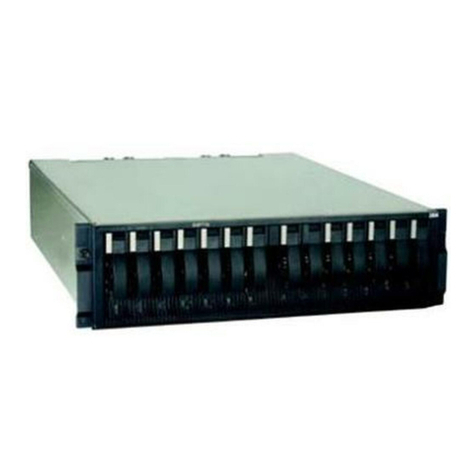
The model number and serial number are on the ID label on the front of the
server, as shown in the following illustration.
Note: The illustrations in this document might differ slightly from your hardware.
You can download the IBM ServerGuide Setup and Installation CD to help you
configure the hardware, install device drivers, and install the operating system.
For a list of supported optional devices for the server, see http://www.ibm.com/
systems/info/x86servers/serverproven/compat/us.
See the Rack Installation Instructions document on the IBM System x Documentation
CD for complete rack installation and removal instructions.
Figure 1. The front of the server
2System x3500 M4 Type 7383: Installation and Service Guide
Table of contents
Other IBM Enclosure manuals

IBM
IBM 3519 Owner's manual

IBM
IBM System Storage EXP2512 Express Storage... Operating instructions

IBM
IBM 7015-R50 Installation and maintenance instructions

IBM
IBM Elastic Storage System 5147-102 User manual

IBM
IBM Small J10 Series User manual

IBM
IBM 9306 001 Owner's manual

IBM
IBM TotalStorage FAStT EXP700 Operating instructions

IBM
IBM 2104 DL1 User manual

IBM
IBM FlashSystem 7200 User manual

IBM
IBM 1U User manual